Modify dimensions
You can modify the created dimensions in several ways: modify the dimension appearance, add dual dimensions, filter dimension tag content, exaggerate dimensions, select to show plate side marks, change the location of short outside dimension texts, or change the dimension extension line length.
Modify dimension properties
You can modify the properties of the dimensions in an open drawing.
Add dual dimensions manually
In dual dimensions, you can show dimensions in different units and format, above and below the dimension line.
-
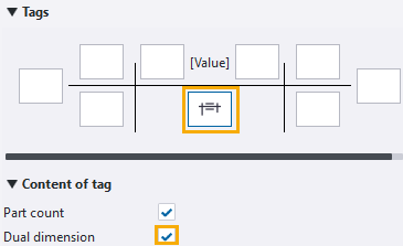
Go to the Tags section, open the Content of tag area, click the
middle tag box, and select the Dual dimension check
box. Add the desired elements in the middle dimension tag.
Example
Below is an example of dual dimensions that use the unit mm and format ###.

You can also add dual dimension automatically.
Filter out dimension tag content
You can remove from a dimension tag some content that has been added in the tag automatically based on the dimension end point locations. First you need to create a drawing view filter that you will use for selecting the content that needs to be removed.
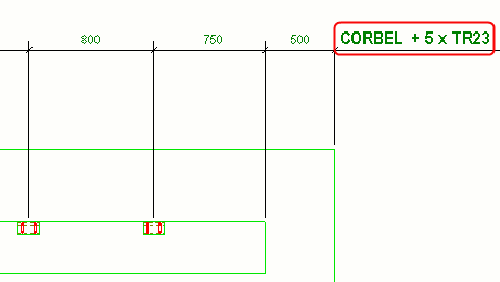
The example below shows a tag that automatically contains the text "CORBEL". You will now remove this text.
-
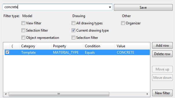
Click Add row and create a filter according to the
example below.
-
Click Modify.
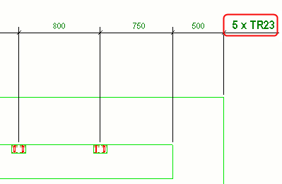
Tekla Structures removes the text "CORBEL" from the dimension tag. The material type of corbel is concrete, and the concrete filter removes all concrete parts from the tag.
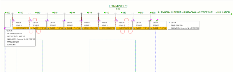
Control dimension tag content with associativity rules
Dimension tag content can also be controlled using associativity rules. Selecting the right associativity rules helps you to easily select objects that need to be shown in the tags and to set up dimension tags, without having to create complex exclusion filters. Only attributes that correspond to the selected objects will be shown in the tags.
This is especially helpful in conflict situations where dimension points might not be associated with the desired objects, because there are other objects in the same dimension point location.
To adjust dimension tag content:
-
In the context menu, select
Show dimension associativity rules, and then select
the objects that you want to show in the dimension tag.
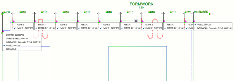
The objects that are not selected from the associativity rule list are immediately filtered out from the tag.
Example:
The properties that correspond to all dimensioned objects are shown in the tag:
After selecting the appropriate objects from the associativity rule list, the objects that are not selected are immediately filtered out from the tag.
Limitations
There are some hard-coded filtering rules in the dimension tag code that you should keep in mind:
- The main part properties are always filtered out if the dimension is
associated to the main part and secondary parts.
Example: You create a dimension that is connected to a main part and a number of embeds (secondary parts). The marks are displayed from the embeds (secondary parts), and the main part is filtered out automatically.
- The attributes of sub-assembly secondary parts are always filtered out.
Instead, the attributes of sub-assembly main parts are shown.
Example: You create a dimension that is connected to embeds. All embed sub-parts need to be filtered out. In addition, if the embed main parts are not in the array, they are added to this array.
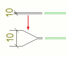
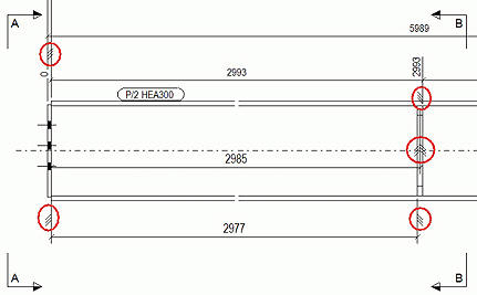
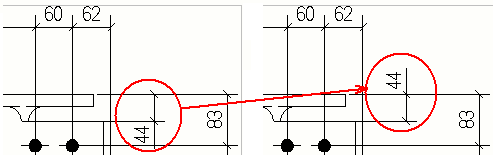
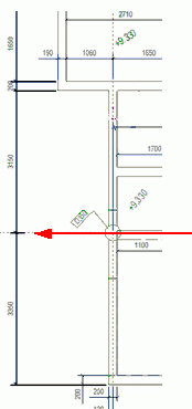
Exaggerate selected dimensions
You can exaggerate narrow dimensions to make them easier to read. When exaggerated, a dimension that is narrower than the limit defined in the Options dialog box is enlarged using the defined scale. If there are many exaggerated dimensions, Tekla Structures arranges them automatically.
-
In dimension properties, go
to the Exaggeration section, and do the following:
- In Exaggerate short dimensions, select Specified.
- Select the Direction of the exaggeration: Left / Down, Right / Up or Both.
- Set the Origin:
 : The origin is
near the dimension line.
: The origin is
near the dimension line. : The origin near
the measured object.
: The origin near
the measured object. - Set the desired exaggeration width, and the position and height for the exaggerated dimension.
-
Click Modify.
The selected dimensions are exaggerated.
Show plate side marks on dimension leader lines
You can show plate side marks on dimension leader lines. The plate side marks indicate whether the dimension point is to the face or center of the part, such as a plate, web, or flange.
-
Modify the other properties of the plate side marks as required:
- Select the left
and right plate side mark.
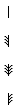
- Set the mark size.
- Set an offset for the mark from the dimension line.
- Adjust the mark color.
- Select the left
and right plate side mark.
-
Click Modify.
The plate side marks are created.
Also check the following topics:
XS_DIMENSION_PLATE_SIDE_MARK_SYMBOL_LEFT
XS_DIMENSION_PLATE_SIDE_MARK_SYMBOL_CENTER
Change the location of short outside dimension texts
You can select to place the texts of short dimensions outside the dimensions. In the dimension properties, set the Short dimensions setting to Outside. You can also select on which side of the extension line the dimension text is placed.
Limitations:
- You can flip only start or end dimensions in a dimension set.
- You can place the dimension text outside the dimensions if there is enough space for the dimension text.
- On the Dimensioning tab, click Flip outside dimension.
- Click the dimension whose location you want to change.
Set the dimension extension line length
You can adjust the length of the dimension extension lines in the dimension properties in an open drawing. You can also adjust the extension line length using advanced options.
-
Select an option from the Short extension line list:
Options
Description
No
Use the short extension line only if the dimension line falls on a grid line:
If you want to exaggerate dimensions, you need to set this option to No.
Yes
Create extension lines all of the same length:
On grid lines only
Use the short extension line automatically if a dimension line falls on a grid line. Elsewhere the extension line will be as usual.
To adjust the extension line lengths, go to and set the following advanced options. These advanced options adjust the extension line length in relation to the text size:
(1) Text height * 1.0 (default). Use XS_DIMENSION_EXTENSION_LINE_AWAY_FACTOR to adjust the length of the dimension extension lines that are facing away from the dimension points.
(2) Text height * 1.5 (default). Use XS_DIMENSION_EXTENSION_LINE_TOWARD_FACTOR to adjust the length of the dimension extension lines that are facing towards the dimension points.