Create views in drawings

Tekla Structures
2023
Tekla Structures

Create views in drawings

After creating a drawing, you can manually add more views.

You can create the following types of views in an existing drawing:

  • Section views
  • Curved section views
  • Detail views
  • Front, top, back, bottom views of parts
  • 3D views of parts
  • Drawing views of an entire model view
  • Drawing views of selected areas in a model view
  • Drawing views of selected areas in a drawing view
Tip: Before you create a new view, create a drawing view filter to adjust what is shown in a view.

Create a section view

You can create section views of the parts in a drawing view in an open drawing. The drawing must contain at least one view.
Note that you cannot create a section view from a 3D view. If you try to pick the points for the view, you will get an error message.

  1. Open the drawing in which you want to create a section view.
  2. On the Views ribbon tab, click Section view to open the Section mark with view property pane.

    If the property pane is not open, hold down Shift and click Section view.

  3. First, set the section mark properties on the Section mark tab:
    1. Modify the section label content.

    2. Modify the section label, cut direction symbol, and cutting line properties.

      For more information about the properties, see Add and modify section marks.

  4. Next, set the section view properties on the View tab:
    1. Click the View button in the Section mark with view property pane.

    2. Modify the drawing view properties as required.

      For more information, see View properties in drawings.

  5. Pick two points to define the position of the section plane.

    It is easier to pick the points if you activate orthogonal snapping: On the File menu, click Settings and select Ortho, or press O.

    For beams, you can also try picking the top line of the beam and then the bottom line of the beam using the snap switch Snap to perpendicular points.

  6. Pick two points to define the direction of the cut box and the section view depth.

    When you pick the cut box, exaggerate a little. You can adjust the view depth and the view boundary also later on.

    The direction of the section is the direction where the section mark arrows are pointing.

  7. Pick the position for the section view.

    A view symbol follows the mouse pointer allowing you to see where you are about to place the section view.

    The depth to the opposite direction is zero (0).

    Tekla Structures creates the section view using the current view properties and section mark properties, adds a section mark in the original view, and places the section view in the position you picked.

    You can modify the created views. For more information, see Modify, arrange, and align drawing views.

    Tip:
    • The view boundary of the created section view remains selected, and you can adjust the depth and the height of the view boundary by dragging the boundary.

    • If necessary, change the view scale of the section view by adjusting the Scale setting.

    • If you want to create another view, start the Section view command again.

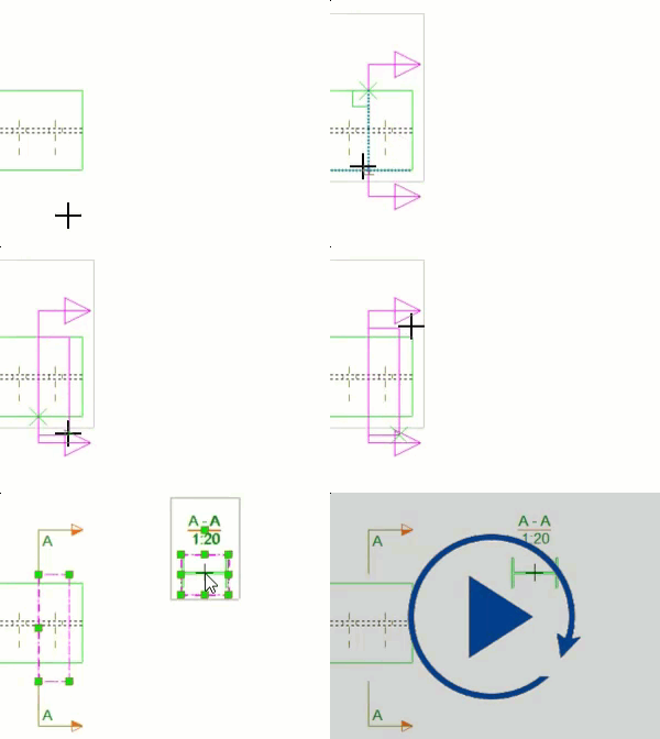
(1) The first two picked points indicate the position of the section plane.

(2) The third picked point indicates the direction of the cut box and the depth of the section view. Here you can exaggerate a little.

(3) The fourth pick finalizes the cut box.

(4) A view symbol follows the mouse pointer while you are placing the section view. The section view is placed in the selected location. The section view remains selected and the view boundary highlighted right after the view creation.

The section mark is drawn in the original view. The view boundary of the section view is also highlighted in the original view right after the view creation.

Create a curved section view

You can create a curved section view of the parts in a drawing view in an open drawing. The drawing must contain at least one view. This tool is useful when you want to visualize an unfolded face of a building or to manage cladding.

Limitation: A curved section view does not work if it is done on a curved object that is vertical or in 3D.

  1. Open the drawing in which you want to create a curved section view.
  2. On the Views ribbon tab, click Section view to open the Section mark with view property pane.

    If the property pane is not open, hold down Shift and click Section view.

  3. First, set the section mark properties on the Section mark tab:
    1. Modify the section label content.

    2. Modify the section label, cut direction symbol, and cutting line properties.

      For more information about the properties, see Add and modify section marks.

  4. Next, set the section view properties on the View tab:
    1. Click the View button in the Section mark with view property pane.

    2. Modify the view properties as required.

      For more information, see View properties in drawings.

  5. Pick three points on the cut plane.
  6. Pick two points to indicate the cut box.
  7. Pick a point to indicate the location of the curved section view.

    A symbol follows the cursor allowing you to see where you are about to place the curved section view.

Tekla Structures creates the curved section view using the current view properties and section mark properties, adds a section mark in the original view, and places the section view in the position you picked.

You can modify the created views. For more information, see Modify, arrange, and align drawing views.

Create a detail view

You can create a detail view from an area that you select in an existing drawing view. By default, the detail view has the same scale as the main view, but in some environments the detail view is scaled up. The detail view has the same direction as the original view. Before creating the detail view label and detail mark, define a start number or letter in the drawing properties.

  1. Open the drawing in which you want to create a detail view.
  2. Check or change the start number or letter for the detail view and symbol:
    1. Double-click the drawing background and select Detail view from the options tree, or in a general arrangement drawing, click the Detail view button.
    2. Change the value when necessary, and click Modify.
  3. On the Views ribbon tab, click Detail view to open the Detail mark with view property pane.

    If the property pane is not open, hold down Shift and click Detail view.

  4. First, set the detail mark properties on the Detail mark tab:
    1. Modify the detail label content, and the related properties, such as mark symbol and detail boundary.

      The shape of the detail boundary you select affects the way you select the area for your detail. For more information about detail marks and their properties, see Add and modify detail marks.

      To change the detail symbol to a custom symbol, use the advanced option XS_DETAIL_MARK_REFERENCE_SYMBOL.

  5. Next, set the detail view properties on the View tab:
    1. Click the View button in the Detail mark with view property pane.

    2. Modify the view properties as required.

      For more information about view properties, see View properties in drawings.

  6. Depending on the selected detail boundary shape, do one of the following:
    • If the shape is Circle, pick the center point of the circle and then pick a point on the circle.

    • If the shape is Rectangle, pick the corner points for the rectangle.

  7. Pick a position for the detail mark.
  8. Pick a position for the detail view.

Tekla Structures creates the detail view using the current detail mark and view properties. The detail view takes the view depth from the original view even if you try to change it. You can change the properties after creating the view.

(1) Detail boundary is set to Circle. You can increase or decrease the detail symbol size by dragging the handle on the detail boundary.

(2) Detail mark

(3) Detail view

(4) Detail view label

Create additional drawing views of parts

You can create additional views of a part within a single-part, cast unit or assembly drawing. You can select the part plane (front, top, back, or bottom) to use or create a 3 D view of the part.

  1. Open a drawing.
  2. On the Views tab, click View of part and select one of the following:
    • Front
    • Top
    • Back
    • Bottom
    • 3D view

    Tekla Structures creates the view using the current view properties. If a plane already has a view in the drawing, a new one is not created.

  3. Click the frame of the new view to open the view properties and modify the properties as required.

    If the drawing property pane is not open, double-click the view frame.

    For example, for 3D views, you may want to modify the view angle.

    For more information, see View properties in drawings.

  4. Click Modify.

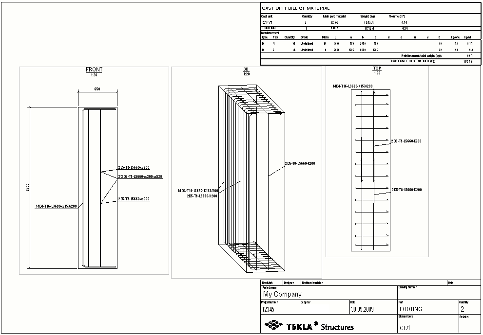
Example

In the example below, the drawing originally contained the front view only. A 3D view and a top view were added. The angle of the 3D view was modified in the view properties.
Create a drawing view of an entire model view

You can create a new drawing view of an entire model view.

  1. Open a drawing.
  2. To open the model view list, on the Views tab, click Model views > Model view list, and leave the list open.
  3. To set the properties for the new view, select View in the drawing property pane object list.

    You might want to change the view scale, for example.

    You can also hold down Shift, and on the Views tab, click Entire model view.

    For more information about view properties, see View properties in drawings.

  4. Open a model view from the model view list.
  5. Click the open model view.

Tekla Structures creates a drawing view using the current drawing view properties. The drawing view has the same depth as the model view. Tekla Structures calculates the boundaries of the view to fit the entire model view into the drawing view, and places the view in the drawing.

Create a drawing view of a selected area in a model view

You can create a new drawing view of the area that you select in the model.

  1. Open a drawing.
  2. To open a model view list, on the Views tab, click Model views > Model view list, and leave the list open.
  3. To set the properties for the new view, select View in the drawing property pane object list.

    You might want to change the view scale, for example.

    Another way to open the viewe properties is to hold down Shift, and on the Views tab, click Area in model view.

    For more information about view properties, see View properties in drawings.

  4. Open a model view from the model view list.
  5. Pick two corners in the model view to define the X and Y dimensions of the drawing view.

    The X and Y directions use the coordinate system of the model view. The view depth is the same as defined in the drawing view properties.

Tekla Structures creates the drawing view.

Create a drawing view of a selected area in a drawing view

You can create a new drawing view of an area that you select in an existing drawing view.

  1. Open a drawing.
  2. On the Views tab, click Area in drawing view.
  3. Select an area in the drawing view for the new drawing view.
  4. Select a location for the new view.
    A symbol representing the view that you are about to place follows the mouse pointer, so it is easy for you to see where to place the view.

Tekla Structures creates a drawing view using the drawing view properties of the original drawing view. To modify the view properties after the view creation, click the view frame. If the property pane is not open, double-click the view frame. For more information about drawing view properties, see View properties in drawings.

Delete a drawing view

Was this helpful?
Previous
Next