Tapered I beam (81)
Tapered I beam (81) creates beams with multiple types of cross-sections and height variations. Cross-section types include I, T, inverted T, and rectangular. The beam height can be tapered, tapered ridge, or constant.
Objects created
-
Beam, one part or multiple parts
-
Stiffeners
-
End blocks
Use for
| Example | Example | Example |
|---|---|---|
|
|
|
|


Before you start
Ensure that you have two points to pick.
Selection order
-
Pick the beam start point.
-
Pick the beam end point.
The beam is created automatically when you pick the end point.
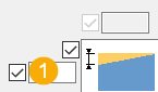
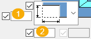
Part identification key

| Description | |
|---|---|
|
1 |
Tapered beam |
|
2 |
Stiffener |
Parameters tab
Use the Parameters tab to define the beam type and the dimensions.
Beam type
| Option | Description |
|---|---|
|
|
Select the beam shape type. |
|
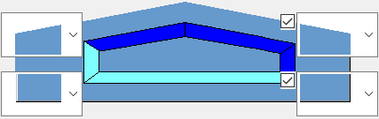
|
Select whether the beam is created as one part or as separate parts. The available options depend on the beam shape type you have selected. The magenta color indicates the main part of the cast unit and the cyan color indicates the secondary part. |


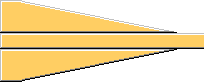
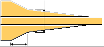
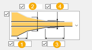
Beam dimensions
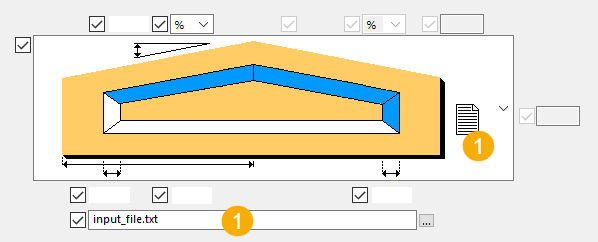
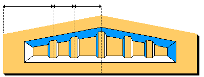
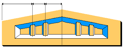
The available dimensions depend on the option you select. The example images below show the dimensions you can define.
| Option | Description |
|---|---|
|
|
1 Height of the beam on the start point side 2 Width of the chamfer on the start point side 3 Location of the ridge. If left empty, the ridge is in the middle. 4 Width of the chamfer on the end point side 5 Angle of the start point edge of the beam, either as percentage or in degrees 6 Angle of the end point edge of the beam, either as a percentage or in degrees 7 Dimension of the beam from the bottom to the highest edge 8 Height of the beam on the end point side |
|
|
1 You can use an external configuration file for defining the dimensions. Define the path to the external file. |

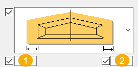
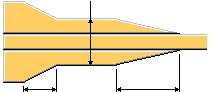
End block dimensions
You can define the end block dimensions with certain beam shape types.
| Option | Description |
|---|---|
|
|
1 Length of the start point end block 2 Length of the end point end block |
|
|
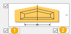
1 Dimension between the start point end block and the middle of the beam 2 Dimension between the end point end block and the middle of the beam |
|
Position h middle |
Select the middle height position:
|
Flange and chamfer dimensions

| Description | |
|---|---|
|
1 |
Height of the top flange |
|
2 |
Height of the top chamfer |
|
3 |
Height of the bottom chamfer |
|
4 |
Height of the bottom flange |
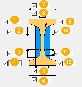
Profile cross section dimensions
The available dimension options depend on the selected beam shape type.
| Description | |
|---|---|
|
1 |
Width of the first top chamfer |
|
2 |
Height of the first top chamfer |
|
3 |
Height of the first bottom chamfer |
|
4 |
Width of the first bottom chamfer |
|
5 |
Width of the end detail |
|
6 |
Width of the bottom flange |
|
7 |
Width of the top flange |
|
8 |
Width of the web |
|
9 |
Width of the second top chamfer |
|
10 |
Height of the second top chamfer |
|
11 |
Height of the second bottom chamfer |
|
12 |
Width of the second bottom chamfer |
Properties tab
Use the Properties tab to define the part properties. These settings affect all parts created by the component: beam parts, stiffeners, and end detail parts.
Properties
| Option | Description |
|---|---|
|
Name |
Part name |
|
Material |
Material grade |
|
Finish |
Part finish |
|
Class |
Part class number |
|
Position on plane |
Horizontal position of the beam in relation to the input points. You can define an additional offset, if needed. |
|
Position at depth |
Depth position of the beam in relation to the input points. You can define an additional offset, if needed. |
|
End offset |
End offsets of the part |
|
Cast unit numbering |
Numbering prefix and start number for the cast unit |
|
Global displacement |
Offset for the part in the x, y, and z direction |
|
Method |
Method to connect the created parts together |
Stiffeners tab
Use the Stiffeners tab to define the stiffener creation.
Stiffener type
| Option | Description |
|---|---|
|
|
Stiffeners are not created. |
|
|
Stiffeners are created. The middle stiffener is created. |
|
|
Stiffeners are created. The middle stiffener is not created. |

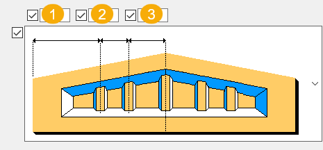
Stiffener dimensions
| Description | |
|---|---|
|
1 |
Dimension from the edge of the beam to the first stiffener |
|
2 |
Dimension from the first stiffener to the second stiffener |
|
3 |
Dimension from the second stiffener to the central stiffener If the central stiffener is not created, this is the dimension from the second stiffener to the center of the beam. Note that if all three values are defined, only values 1 and 2 will be used. |

| Description | |
|---|---|
|
1 |
Thickess of the stiffener |
|
2 |
Width of the stiffener |
|
3 |
Width of the top part of the stiffener |
Connection method
Select how the stiffeners are connected to the main part.
End details tab
Use the End details tab to define the end detail creation.
End detail shape and dimensions
Select the top and bottom end detail on both sides of the beam.
| Option | Description |
|---|---|
|
|
No end detail at the top |
|
|
Horizontal dimension of the added block |
|
|
Vertical dimension of the added block |
|
|
1 Vertical dimension of the cut 2 Horizontal dimension of the cut |
|
|
No end detail at the bottom |
|
|
1 Vertical dimension of the cut 2 Horizontal dimension of the cut |
|
|
1 Vertical dimension of the cut 2 Horizontal dimension of the cut 3 Horizontal dimension of the first chamfer |


End block shape
| Option | Description |
|---|---|
|
|
End blocks are not created. |
|
|
End blocks without chamfers are created. |
|
|
End blocks with one chamfer are created. |
|
|
End blocks with two chamfers are created. |
|
|
End blocks with three chamfers are created. |

End block dimensions
| Description | |
|---|---|
|
1 |
Length of the first chamfer |
|
2 |
Width of the end blocks |
|
3 |
Width of the end blocks at the end of the second chamfers |
|
4 |
Width of the third chamfers If there are two chamfers, this is the width of the second chamfer. |
UDA tab
Use the UDA tab to define the user-defined attributes.
-
String for text
-
Integer for integers
-
Float for values with decimals after a comma
-
Option for predefined values