Create cuts
You can use cuts to shape a part. Do not use cuts to otherwise change the length of a part in the model.
Cut objects with a line
Use line cuts to shape the end of a beam or column, or to cut a rebar set. A line cut cuts the end of a beam on a plane that passes through the points you pick. Tekla Structures displays the cut line using dash-and-dot lines.
- On the Edit tab, click Line cut.
- Select the object you want to cut.
- Pick the first point of the cutting line.
- Pick the second point of the cutting line.
- Pick the side you want to remove.
- If you want to modify the cut, use direct modification.
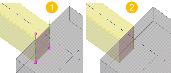
(1) Cuts are displayed using dash-and-dot lines
(2) Cut lines can be hidden
Cut objects with a polygon
A polygon cut cuts a part or a rebar set using a polygonal shape. Tekla Structures displays the cut using dash-and-dot lines.

(1) Polygon-shaped cut
(2) Cut lines can be hidden
Note:
Tekla Structures uses the parametric profile BL to create polygonal cuts.
If you are unable to create polygonal cuts, ensure that the BL profile is defined in the profitab.inp file in ..\ProgramData\Trimble\Tekla Structures\<version>\environments\<environment>\profil as follows:
BL ! PL ! -1 !
						! 1 ! 2 ! ! !
Cut objects with a part
You can cut a part or a rebar set using another part. Tekla Structures displays the cut using dash-and-dot lines. Note that you can cut parts that already have cuts. That can be useful, for example, when you want to create more sophisticated cut shapes.
-
Delete the cutting part.
-
Ensure that the
 Select cuts and added materials selection
switch is off.
Select cuts and added materials selection
switch is off.
- Select the cutting part and press Delete.
-
Ensure that the
(1) Cuts are displayed using dash-and-dot lines
(2) Cut lines can be hidden
Note:
Do not create cuts with the same planes or vertices. Otherwise, it may be unclear what should be cut away
Hide cut lines in a model view
- Double-click the view to open the View Properties dialog box.
- Click Display... to open the Display dialog box.
- Ensure that the Cuts and added material option is not selected in the display settings.
- Click Modify.
Tips on how to cut efficiently
-
Avoid part faces
Avoid creating cuts that are exactly on the part planes or go through vertices. Try to position the cut at least 0.3 mm outside of the part planes.
-
Use polygon cuts
Whenever possible, use polygon cuts. The Polygon cut command automatically extends the cut slightly outside of the part face. Note that after creating the polygon, you may have to adjust the position of the handles manually.
-
Use edge chamfers
Whenever possible, use edge chamfers instead of small cuts, especially in components.
-
Tips for flange cuts
When cutting a flange, if the cutting part cuts very slightly the web as well (at least 0.3 mm), the cut is more likely to succeed. For example, if you are cutting a beam that has roundings, it may be useful to cut even further onto the web than just the flange thickness.
-
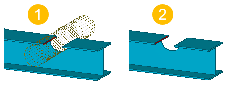
Tips for round tube cuts
Use the Round tube (23) component for round tube cuts. The component automatically rotates the cutting part until a successful cut position is found. If the component fails, rotate the cutting part slightly until you find a successful cut position.
Note:
If a cut fails, Tekla Structures displays the cutting part using dash-and-dot lines. An error notification is printed in the session history log stating which part and which cut caused the failure.
To locate the failure in the model, click a row that contains an ID number in the session history log. Tekla Structures selects the corresponding part and cut in the model.
Polygon cut properties
Use the Polygon cut properties in the property pane to view and modify the properties of a polygon cut.
Note that the polygon cut properties are available in the property pane only after a polygon cut has been created and selected. You cannot access or modify the cut properties before the cut is created.
If you have customized the property pane layout, the list of properties may be different.
|
Setting |
Description |
|---|---|
|
General |
|
|
Name |
Name of the polygon cut. |
|
Profile |
Profile of the polygon cut, by default parametric profile BL. |
|
Material |
Material of the polygon cut, by default ANTIMATERIAL. The cut material cannot be changed. |
|
Class |
Use to group polygon cuts. For example, you can display cuts of different classes in different colors. |
|
Position |
|
|
At depth |
Position depth of the polygon cut. |
|
More |
|
|
UDAs |
Click the User-defined attributes button to open the user-defined attributes (UDAs) of the cut. UDAs provide more information about the cuts. |
Part cut properties
Part cut uses the properties of the cutting part. For example, if the cutting part is steel beam, part cut uses the Steel beam cut properties. The default part cut properties depend on the used cutting part.
Note that the part cut properties are available in the property pane only after a part cut has been created and selected. You cannot access or modify the cut properties before the cut is created.
The following part cut properties are available:
-
Steel beam cut
-
Steel column cut
-
Steel spiral beam cut
-
Steel item cut
-
Concrete beam cut
-
Concrete column cut
-
Concrete panel cut
-
Concrete slab cut
-
Concrete spiral beam cut
-
Bent plate cut
-
Pad footing cut
-
Strip footing cut
-
Concrete item cut
If needed, you can customize the property pane layouts of part cuts.