Windbracing 2 (16)
Windbracing 2 (16) connects a single hollow brace to a beam or a column, using a connection plate, threaded rod, and nuts. Round plates are welded to the connection plate and the connection plate bolted to the beam or column.
Objects created
-
Connection plate
-
Round plates
-
Shim plate
-
Threaded rod
-
Nuts on rod
-
Tube profile
Use for
| Situation | Description |
|---|---|
|
|
Windbracing, connection plate is bolted to the column. Round plates are welded to the connection plate. |
|
|
Windbracing, connection plate is bolted to the column. Round plates are welded to the connection plate. |
|
|
Windbracing, without round plate. |
|
|
Windbracing, triangular plate. |


Before you start
Create a beam or a column and one brace.
Selection order
-
Select the beam or the column (main part).
-
Select the brace (secondary part).
The connection is created automatically when you select the secondary part.
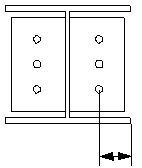
Part identification key

| Description | |
|---|---|
|
1 |
Beam - main part |
|
2 |
Brace - secondary part |
|
3 |
Windbracing connection with connection plate, round plate, and bolts |
Picture tab
Use the Picture tab to define the size and the position of the connection plate and the round plate.
Plate dimensions

| Description | |
|---|---|
|
1 |
Width of the round plate. |
|
2 |
Height of the round plate. |
|
3 |
Thickness of the connection plate. |
|
4 |
Thickness of the round plate. |
|
5 |
Distance from the top of the connection plate to the center of the slotted hole. |
|
6 |
Vertical distance from the center of the slotted hole to the center of the bolt group. |
|
7 |
Height of the connection plate. |
|
8 |
Width of the connection plate. |
Round plate or tube
| Option | Description |
|---|---|
|
|
Round plates with a threaded rod. |
|
|
Tapered tube with a threaded rod. |
|
|
Threaded rod. |
|
|
Triangular plate on the tie rod side with a threaded rod. |
|
|
Triangular plate at the end side with a threaded rod. |
|
|
Triangular plates on both sides with a threaded rod. |
|
|
No plates or a threaded rod. |
|
|
Triangular plate on the tie rod side. |
|
|
Triangular plate at the end side. |
|
|
Triangular plates on both sides. |
|
|
No plates or a threaded rod. |
|
|
Rod welded to an L profile. |


Create assembly with connecting parts
Define whether or not the connecting parts (shim plate, washer, nuts) are welded together.
Weld connecting parts
Define which parts are welded.
Parts tab
Use the Parts tab to define the part properties.
Parts
| Option | Description |
|---|---|
|
Connection plate |
Thickness, width, and height of the connection plate. |
|
Round plate |
Thickness, width, and height of the round plate. |
|
Filler |
Select the profile from the profile catalog. Tekla Structures creates a simplified shim plate. In reality, the plate is curved on one side, equal to the radius of the round plate. Enter the width and height, for example PL50*50 or 50*50. |
|
Washer |
Select the profile from the profile catalog. |
|
Nut |
Select the profile from the profile catalog. |
|
Extra nut |
Select the profile from the profile catalog. |
|
Tube |
Select the profile from the profile catalog. |
|
Option |
Description |
Default |
|---|---|---|
|
Pos_No |
Prefix and start number for the part position number. Some components have a second row of fields where you can enter the assembly position number. |
The default part start number is defined in the Components settings in . |
|
Material |
Material grade. |
The default material is defined in the Part material box in the Components settings in . |
|
Name |
Name that is shown in drawings and reports. |
|
|
Class |
Part class number. |
|
|
Comment |
Add a comment about the part. |
Thickness dimensions

| Description | |
|---|---|
|
1 |
Thickness of the shim plate. |
|
2 |
Thickness of the washer. |
|
3 |
Thickness of the nut. |
|
4 |
Thickness of the extra nut. |
Parameters tab
Use the Parameters tab to define the rod and hole dimensions.
Hole creation
Define how the hole is created in the main part.
| Option | Example |
|---|---|
|
Hole by part cut |
|
|
Hole by bolt |
|
|
Hole by part cut and bolt |
|


Connection method
Define how the round plates are joined to the connection plate.
Dimensions

| Description | |
|---|---|
|
1 |
Diameter of the rod end. |
|
2 |
Offset from the secondary part edges. |
|
3 |
Length of the connecting piece. You can define this if a tube is created. Length is measured along the center line.
|
|
4 |
Slot length in the main part. |
|
5 |
Rod length to the center of the main part. |
|
6 |
Rod length to the center of the main part. |
|
7 |
Define how the callote is welded. When not welded, the calotte is connected to the main part with a bolted connection. |
|
8 |
Vertical offset of the round plates. Define a value to offset the plates in the vertical direction.
|
|
9 |
Slotted hole height. |
|
10 |
Slotted hole width. |
|
11 |
Define how the rod connection is welded. |
|
12 |
Slotted hole height in the main part. |
|
13 |
Slotted hole width in the main part. |


Bolts tab
Use the Bolts tab to define the bolt group dimensions and bolt properties.
Bolt group dimensions

| Description | |
|---|---|
|
1 |
Select how to measure the dimensions for horizontal bolt group position.
|
|
2 |
Dimension for horizontal bolt group position. |
|
3 |
Bolt edge distance. Edge distance is the distance from the center of a bolt to the edge of the part. |
|
4 |
Number of bolts. |
|
5 |
Bolt spacing. Use a space to separate bolt spacing values. Enter a value for each space between bolts. For example, if there are 3 bolts, enter 2 values. |
|
Select how to measure the dimensions for vertical bolt group position.
|
|
|
Dimension for vertical bolt group position. |


Basic bolt properties
| Option | Description | Default |
|---|---|---|
|
Bolt size |
Bolt diameter. |
Available sizes are defined in the bolt assembly catalog. 16 mm |
|
Bolt standard |
Bolt standard to be used inside the component. |
Available standards are defined in the bolt assembly catalog. 4014-8.8 |
|
Tolerance |
Gap between the bolt and the hole. |
4 mm |
|
Thread in mat |
Defines whether the thread may be within the bolted parts when bolts are used with a shaft. This has no effect when full-threaded bolts are used. |
Yes |
|
Site/Workshop |
Location where the bolts should be attached. |
Site |
Cut length
Defines the depth at which Tekla Structures searches for the sections of the bolted parts. You can determine whether the bolt will go through one flange or two.
Slotted holes
You can define slotted, oversized, or tapped holes.

|
Option |
Description |
Default |
|---|---|---|
|
1 |
Vertical dimension of slotted hole. |
0, which results in a round hole. |
|
2 |
Horizontal dimension of slotted hole, or allowance for oversized holes. |
0, which results in a round hole. |
|
Hole type |
Slotted creates slotted holes. Oversized creates oversized or tapped holes. No hole does not create holes. |
|
|
Rotate Slots |
When the hole type is Slotted, this option rotates the slotted holes. |
|
|
Slots in |
Part(s) in which slotted holes are created. The options depend on the component in question. |
Examples of slotted holes

Bolt assembly
The selected check boxes define which component objects (bolt, washers, and nuts) are used in the bolt assembly.
If you want to create a hole only, clear all the check boxes.

To modify the bolt assembly in an existing component, select the Effect in modify check box and click Modify.
Bolt length increase
Define how much the bolt length is increased. Use this option when, for example, painting requires the bolt length to be increased.

UDA tab
Use the UDA tab to define the user-defined attributes for the connection plate.
You can define the fabricator name, type, nomination, article number, product code, and product description.
General
Click the link below to find out more:
Analysis tab
Click the link below to find out more:
Welds
Click the link below to find out more: