Formwork placing tools - Walls
Formwork placing tools - Walls is a set of components that helps in detailed modeling of different wall panel formwork systems. These components are placing tools, and therefore you need to have all relevant formwork products such as wall panels, corner conditions, clamps, and pouring platforms available in the Applications & components catalog.
You can get the formwork products provided by formwork suppliers from Tekla Warehouse, for example. In addition, Formwork placing tools - Walls requires additional configuration files that contain the necessary information about the formwork product components. These configuration files may come with the formwork product catalogs provided by formwork suppliers, but you can create the configuration files yourself as well.
Formwork placing tools - Walls contains tools to place and modify the following formwork elements:
-
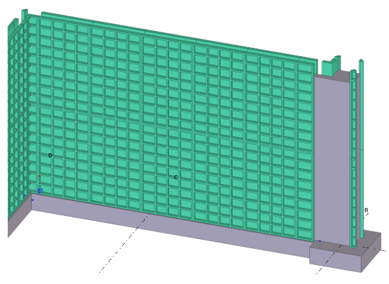
formwork wall panels typically appearing as two-dimensional arrays covering a certain area
-
different kinds of corner conditions
-
an array of ties between two formwork panels
-
an array of clamps, locks, or brackets at the joining edge between two formwork panels to keep the formwork together
-
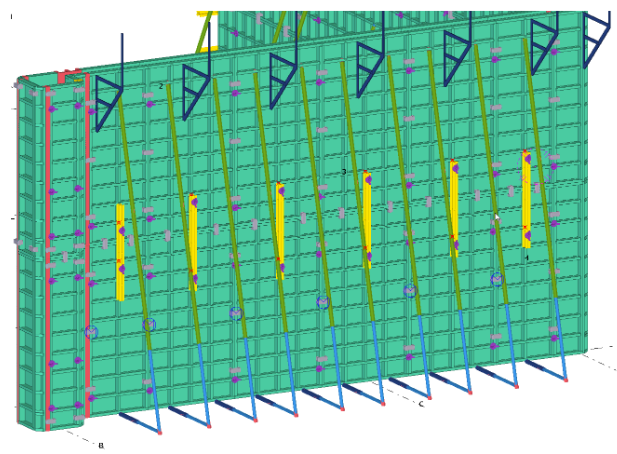
supporting braces for a single formwork panel
-
an array of pouring platforms at the top edge of formwork panels
-
fillers to fill the gaps between two formwork panels
Because Formwork placing tools - Walls consists of a set of sub-tools which are combined in one dialog box, each tab is an individual sub-tool. Both the Formwork placing tools - Walls and the sub-tools are available in Applications and components catalog.
Most of the settings in the components are preset. You can control the different settings by selecting a suitable options in the dialog box. These preset settings are organized according to the formwork supplier and the product families.
However, if you create your own configuration files, you can use the values in the configuration files instead of the preset values.
You can access the Formwork placing tools - Walls in the Concrete Contractor, General Contractor and Rebar Detailer roles in the Default environment.
Panel tab
Use the Panel tab to model an array of formwork panels on one side or on two sides of a cast-in-place wall.
The actual formwork panels are custom parts. In addition to the custom parts, some additional data of the products is needed from the configuration files.
-
On the Panel tab, in the Formwork supplier and Product family list, select the suitable options.
The options vary depending on which catalogs and tool configurations you have in use.
-
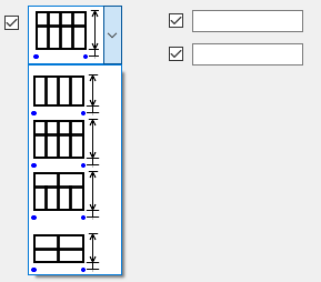
Select the panel size in the Formwork panel list, and set the other panel properties such as the layout, height, and fill location.
-
Click Apply and Insert new to start placing the wall panels.
Move the mouse pointer over pour objects or concrete parts to select a suitable location.
-
Pick the start point and the end point of the formwork wall panel.
A preview of what the panels would look like after being placed is shown and you can decide which panels should be created. You can also change the panel layout afterwards by using direct modification.
| Option | Description |
|---|---|
|
Formwork supplier Product family |
Select the formwork supplier and the product family. |
|
Formwork panel |
Select the panel size. If the total length of the panel array does not match with the panel width, smaller panels with the same height are automatically placed in the array near the fill location (start/middle/end of the array). |
|
Avoid panels |
Define which panels are avoided during the automatic insertion. |
|
Panel layout |
Override the default panel widths. When you insert the array for the first time, leave the value empty and modify the panel widths by using direct modification.
|
|
|
Select the layout of the panel array. Enter the offset from the wall bottom and the total height of the panel array. |
|
One side Two sides |
Select whether the panels are created on one side or on both sides of the wall. You can modify the wall thickness. When the walls are inserted, the applied wall thickness is overridden with the actual wall thickness. |
|
Fill location |
Use the Fill location option to control where the empty space for the filler is located. |
|
Add to pour unit |
Select whether the panels and all accessories related to the panels are added to the pour or not. |
|
Select new pour... |
The initial pour is identified automatically when the panels are inserted. To change the selected pour, click the Select new pour... button and select a new pour. Note that there is no automatic recognition of a new pour if you decide to move the formwork panels, or if you add pour breaks which change the pours. |
|
Insert new |
Click the Insert new button to start inserting new formwork panel arrays. |
|
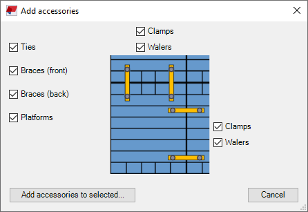
Add accessories to selected |
Add various accessories automatically to the selected panels.
Select the check boxes for the accessories you want to add. Note that for clamps and walers you can control separately the creation at horizontal and/or vertical edges. |
Conditions tab
A condition is a set of formwork components, such as custom parts, parts or other items, designed for special geometries in the wall. Conditions create the formwork at special locations in the walls, such as L, T, and X corners, bulkhead at the end of a wall, or pilasters at pour ends or at the middle of the wall. Each different type of a special geometry is its own condition type.
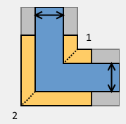
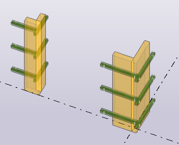
Each condition consists of two or more sub-assemblies of the formwork components, depending on the condition type. For example, the L corner contains the inner corner assembly (1) and the external corner assembly (2). When inserted in the model, the location of these assemblies is controlled with the main insertion points and the two wall thickness parameters.
Use the Conditions tab to create a condition that consists of two or more sub-assemblies of formwork components.
-
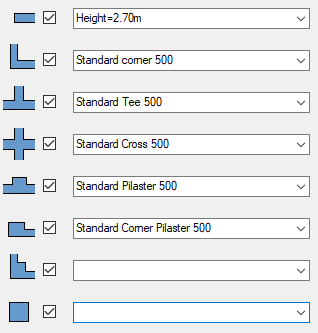
On the Conditions tab, select what type of condition to use by clicking the condition icon, and set the values to be applied for the selected condition.
-
Click Apply and Insert new to start placing the conditions.
-
Move the mouse pointer on the corner edges, pilaster edges, or ends of the pours or parts.
Formwork placing tools - Walls automatically recognizes the condition type and wall thickness properties.
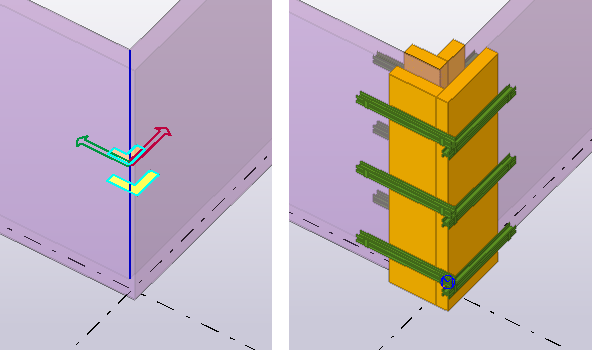
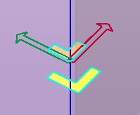
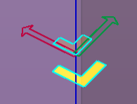
Two arrows and a preview of the condition parts to be created is shown. The red arrow indicates the first direction and the green arrow indicates the second direction.
In the example below, the longer panel becomes parallel to the red arrow, and the shorter panel will be parallel to the green arrow. Depending on the case, you may switch the arrows by moving the mouse on the other side of the edge.
-
Click to place the conditions.
In some cases the condition tool may not recognize the condition type correctly. For example, if you want to insert an L corner to a location where the other side of the wall is very short it may happen that the condition tool is trying to insert a corner pilaster.
| Option | Description |
|---|---|
|
|
Select the condition to be created. The selection is specific for each type of condition. Click the condition icon to select the condition type to be used. |
|
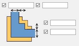
|
Modify the dimensions that control the location of condition sub-items in relation to the insertion point. When you insert a new condition, these dimensions are overridden by the calculated values based on the actual insertion location and condition type. |
|
Offset from bottom |
Define the vertical offset for the condition from the bottom of the wall. |
|
Number of stacked conditions |
To insert two or more vertically stacked conditions, enter the number of stacked conditions. |
|
Height |
Height of one stack when the conditions are stacked. |
|
Left/right corner |
Select how the conditions are inserted if you use the left-hand side placement. If you select Rotate, the condition always switches the red/green axis to a right-hand side placement. If you select Mirror, the left-hand side placement is allowed. Right-hand side placement:
Left-hand side placement:
|
|
Filler configuration |
Define which filler type is used when you place a condition which includes a filler. |
|
Configure |
Open the Condition setup dialog box to modify the existing conditions or to define new conditions. |
Define a new condition
Defining a new condition has two phases. First, you need create the needed sub-assemblies. Once you have all the needed sub-assemblies available, you can define a new condition by giving it a name and defining which sub-assemblies are used in the new condition.
To define a new condition or to modify existing condition definitions, click the Configure button. The Condition setup dialog box opens where you can do the needed modifications.
| Option | Description |
|---|---|
|
Condition setup file |
Conditions are saved in external data files (xxxx.FormworkTools.Conditions.csv). Select the file to add, modify or delete the defined conditions. |
|
Save Save as New |
Click Save or Save as to save any changes. Click New to create a new empty file. |
|
Condition type |
In the list, select the condition type to be modified. The list shows the existing conditions if there are any. If you have one or more existing conditions of the selected type, you can select the current condition in the list. When the condition is selected, the current definition values are shown and can be set or modified on the right-hand side of the dialog box. Click Click Click |
|
Formwork supplier Product family Condition |
The condition has the supplier and the family properties. The conditions are available only when the supplier and the family are matching. The condition names need to be unique. Decide about naming conventions so that the names are as descriptive as possible. |
|
|
The condition can have 2-5 sub-conditions, depending on the condition type. One condition must have at least one sub-condition defined as otherwise it does not create anything. Click Click the Test button to verify the output of the selected sub-assembly. To test the sub-assembly, pick a point in the model. The tool creates a sample wall and the sub-conditions with right side and left side placement. After you have done the testing, you can delete model objects that were created for testing purposes. |
|
Total height for stacking |
The total height of the condition can be calculated automatically based on the selected sub-conditions, or you can give the height. The total height is used as the spacing value when two or more conditions are stacked vertically. If the condition contains some parts sticking out and this part is overlapping in the stack, you may need to enter the total height manually. |
|
Left/right corner |
Test and verify how the Mirror and Rotate options affect the output of the condition. |
|
Test condition |
Test and verify the output of the whole condition, including all sub-conditions. To test the condition, pick a point in the model. The tool creates a sample wall and two conditions with right side and left side placement. After you have done the testing, you can delete the model objects that were created for testing purposes. |
 to copy
the selected condition.
to copy
the selected condition. to delete
the condition.
to delete
the condition.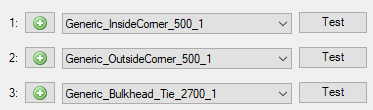
Create a new corner sub-assembly
The corner sub-assemblies are created using Formwork corner sub-assembly wizard.
Typically, the corner sub-assembly contains formwork products at one side (inner or external) of the corner, or at some corner in a pilaster.
The outcome of the wizard is stored in an external file with a name.
To open the dialog box, click
 in the
Condition setup dialog box on a condition that requires a
corner sub-assembly. Alternatively, you can search for the Formwork
corner sub-assembly wizard in the Applications and
components catalog.
in the
Condition setup dialog box on a condition that requires a
corner sub-assembly. Alternatively, you can search for the Formwork
corner sub-assembly wizard in the Applications and
components catalog.
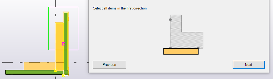
Before you can start creating the corner sub-assemblies, you need to have an external or inner corner formwork in the model. When you have created the corner formwork, you can start the wizard.
-
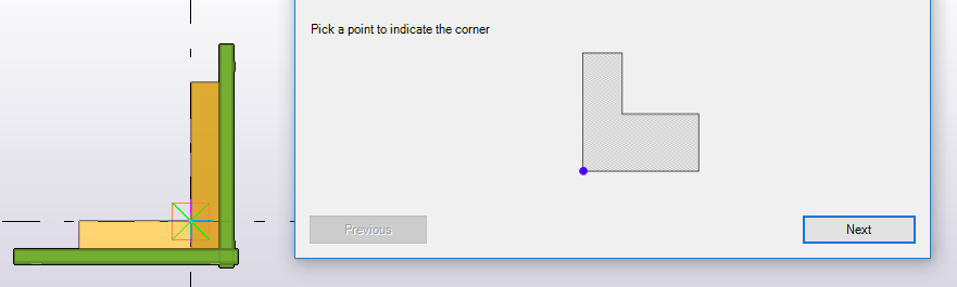
Pick the first corner point.
This point will be placed exactly to the external or to the internal corner of the concrete in the wall in the final condition placement. Note that after you have picked the point, the wizard steps forward automatically. You can step back to re-pick a new point.
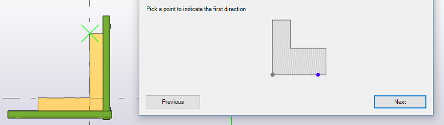
-
Pick a point showing the direction of the first wall.
This is typically the red arrow in condition placing.
-
Select all formwork items belonging to the first wall.
In practice, these formwork items will be parallel to the first wall when placing the sub-assembly of the condition.
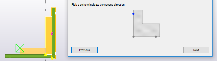
-
Pick a point showing the direction of the second wall.
This is typically the green arrow in condition placing, and perpendicular to the first wall.
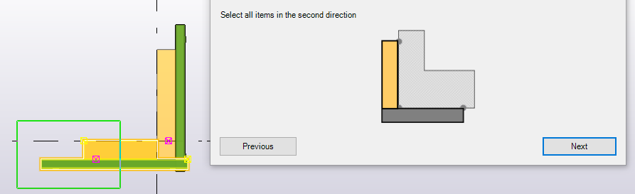
-
Select all formwork items belonging to the second wall.
Typically, these formwork items will be parallel to the second wall when placing the sub-assembly of the condition.
Enter a file name to save the corner sub-assembly. Click Finish to close the wizard.
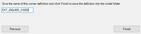
All corner sub-assemblies are saved in the Formwork tools folder in the model folder.
If you want to use the conditions in other models, you can copy or move the files and the condition setup files to any of the system folders. To ensure that the conditions work in other models, all custom components that the conditions use must exist in the Applications and components catalog.
Create a new panel sub-assembly
The panel sub-assemblies are created using Formwork panel sub-assembly wizard.
The outcome of the wizard is stored in an external file with a name.
To open the dialog box, click
in the
Condition setup dialog box on a condition that requires a
panel sub-assembly. Alternatively, you can search for the Formwork
panel sub-assembly wizard in the Applications and
components catalog.
Before you can start creating the panel sub-assemblies, you need to have a formwork panel and all necessary accessories in the model. When you have created the formwork structure, you can start the wizard.
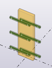
-
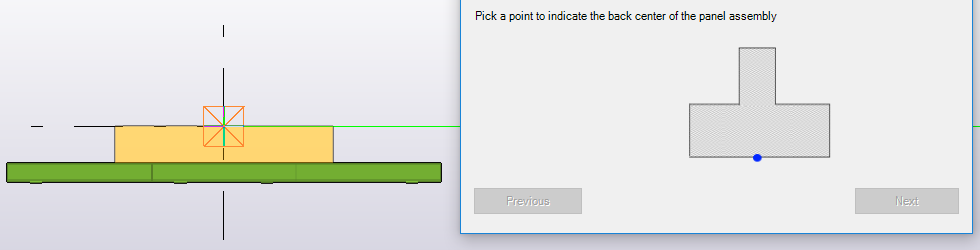
Pick the center point of the panel sub-assembly.
This point will be placed exactly to the center of the concrete wall in the final condition placement. Note that after you have picked the point, the wizard steps forward automatically. You can step back to re-pick a new point.
-
Pick a point showing the direction of the wall.

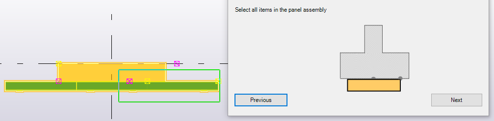
-
Select all formwork items belonging to the panel sub-assembly, and click Next.
-
Enter a file name to save the panel sub-assembly. Click Finish to close the wizard.
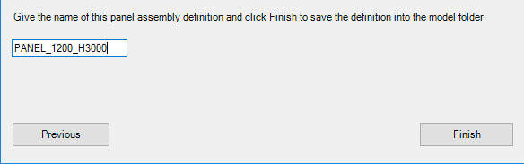
All panel sub-assemblies are saved in the Formwork tools folder in the model folder.
If you want to use the conditions in other models, you can copy or move the files and the condition setup files to any of the system folders. To ensure that the conditions work in other models, all custom components that the conditions use must exist in the Applications and components catalog.
Fillers tab
Use the Fillers tab to create filler items to fill the gaps between two formwork panels.

Note that this functionality does not work between condition and a panel, meaning that the gap at the end of the wall cannot be filled with this setup.
-
On the Fillers tab, select the filler in the Filler configuration list, and set the other filler properties.
-
Click Apply and either Select single panel or Select two panels, depending on how you want to insert the fillers.
-
To insert the filler by selecting a single panel, select the formwork panel and a point to indicate the location (left, right, top, bottom of the panel) and the width of the filler.
-
To insert the filler by selecting two adjacent panels, select the first formwork panel, and then select the second formwork panel.
-
Ties tab
Use the Ties tab to insert an array of ties between two formwork panels on the opposite sides of the wall.
-
On the Ties tab, select the tie in the Tie type list, and set the other tie properties.
-
To add ties manually, set Tie layout to Single tie, Left side, or Right side.
-
Click Apply and Insert new to start placing ties.
-
In the model, hover your mouse pointer over the panel and pick the points where you want to add ties.
-
Alternatively, to add ties automatically, set Tie layout to Preset array. Select the panel, click Apply and Add to selected. The ties are placed automatically.
-
If you want modify ties:
-
To adjust tie position, select a tie array, and drag the handle to move the tie to the position you want.
-
To add new ties, duplicate the existing ones. Hold down the Ctrl key, and drag a tie to a new position.
-
To delete individual ties, select a tie and press the Delete key.
-
To change the properties, spacing and/or start distances, modify the properties in the dialog box and click Modify.
-
Clamps tab
Use the Clamps tab to insert a linear array of clamps, locks, or brackets at the joining edges between two formwork panels to keep the formwork together. Clamp placing works in the same way as the tie placing.
-
On the Clamps tab, select the clamp in the Clamp type list, and set the other clamp properties.
-
To add clamps manually, set Clamp layout to Single clamp. With the Custom array option you can set the offset and spacing.
-
Click Apply and Insert new to start placing clamps.
-
In the model, hover your mouse pointer over the panel, and pick the points where you want to add clamps.
-
Alternatively, to add clamps automatically, set Clamp layout to Preset array. Select the panel, click Apply and Add to selected.
The Add accessories dialog box opens where you can select which accessories are added with the clamps. Click Add accessories to selected. The clamps and other accessories are placed automatically to the selected panels.
-
If you want modify clamps:
-
To adjust a clamp position, select a clamp, and drag the handle to move the clamp to the position you want.
-
To add new clamps, duplicate the existing ones. Hold down the Ctrl key, and drag a clamp to a new position.
-
To delete individual clamps, select a clamp and press the Delete key.
-
To change the properties, spacing and/or start distances, modify the properties in the dialog box and click Modify.
-
Walers tab
Use the Walers tab to insert walers to formwork panels. Typically, a waler is used to connect two panels on top of each other but it can also be placed in one single panel. The waler typically consists of the waler beam and two lock devices fixing the waler to the panel.
-
On the Walers tab, select the waler in the Waler type list, and set the other waler properties.
-
Enter the longitudinal offset. Leave the value empty to get the waler beam centered between the input points.
-
Click Apply and Insert new to start placing walers.
-
In the model, hover your mouse pointer over the panel and pick the first preset point. This is the first input point of the waler beam and the location for the first lock device.
-
Move the mouse pointer on the next panel and pick the second preset point. This is the end point of the waler beam and the location for the second lock device.
If you did not enter the longitudinal offset value, the waler beam is centered between the picked points. Otherwise, the waler beam starts at the given offset from the first picked point.
Alternatively, to add walers automatically, click Apply and Add to selected. The Add accessories dialog box opens where you can select which accessories are added with the walers. Click Add accessories to selected. The walers and other accessories are placed automatically to the selected panels.
-
If you want modify walers:
-
To adjust a waler position, select a waler, and drag the point handle to move the waler to the position you want.
By holding down the Alt key, you can drag the point anywhere, even to a different panel.
-
To change the longitudinal offset, drag the point handle between the picked points.
-
To add new walers, hold down the Ctrl key, and drag a main handle of a waler to a new position.
-
Braces tab
Use the Braces tab to insert supporting braces for a single formwork panel.
-
On the Braces tab, select the brace layout in the Brace layout list, and set the other brace properties.
To add braces manually, set Braces layout to Single brace. With the Custom array option you can set the offset and spacing.
-
Click Apply and Insert new to start placing braces.
-
In the model, hover your mouse pointer over the panel and pick the points where you want to add braces.
-
Alternatively, to add braces automatically, set Brace layout to Preset array. Select the panel, click Apply and Add to selected. The Add accessories dialog box opens where you can select which accessories are added with the braces. Click Add accessories to selected and the braces and other accessories are placed automatically to the selected panels.
Platforms tab
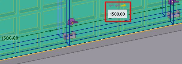
Use the Platforms tab to insert an array of pour platforms at the top edge of formwork panels.
-
On the Platforms tab, select the platform type in the Platform type list, and set the platform spacing and offset.
-
Click Apply and Insert new to start placing platforms.
-
In the model, hover your mouse pointer over the panel and pick the start and end points to create a linear array of platforms along the top edge of the panel.
-
Alternatively, to add platforms automatically, select the panel and click Add to selected. Platforms are added automatically to the selected panels.