Railings (S77)
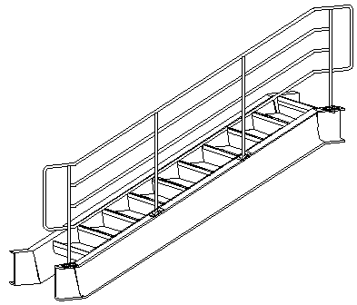
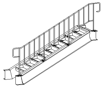
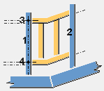
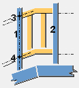
Railings (S77) creates railings connected to two or more stanchions. The railings can be handrails in stairs or guardrails in a horizontal beam or slab.
Objects created
-
Top rail
-
Middle rails (horizontal or vertical)
-
Bottom rail
-
Panels
-
Bends
Use for
|
Situation |
Description |
|---|---|
|
|
Horizontal railings |
|
|
Horizontal railings connected to four stanchions |
|
|
Vertical railings connected to four stanchions |
|
|
Guardrail with vertical railings |
Before you start
Create the stanchions using, for example, Stanchions (S76).
Selection order
-
Select the first stanchion.
-
If the stanchions are created with Stanchions (S76), and on the Picture tab the Stanchion selection is set to Use all or Default, the railings are created when you click the middle mouse button.
OR
-
Select the first stanchion.
-
If the stanchions are created separately, or on the Picture tab the Stanchion selection is set to Use selected, select the second, third, and so on, stanchion.
The order in which the stanchions are selected defines the positioning of the railings. The two first selected stanchions define the left and right directions of the railings.
-
Click the middle mouse button to create the railings.
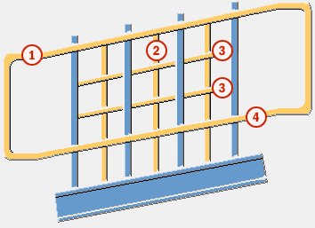
Part identification key
|
Part |
|
|---|---|
|
1 |
Top rail |
|
2 |
Vertical rails |
|
3 |
Middle rails |
|
4 |
Bottom rail |
Picture tab
Use the Picture tab to control the railings and the closures.
Stanchion selection
By default, the Use all option is used.
-
Use selected: the railings are created only to the selected stanchions.
-
Use all: select this option when the stanchions are created with Stanchions (S76).
Part positions

|
Description |
Default |
|
|---|---|---|
|
1 |
Horizontal length of the closure in the top rail and where the bending is created in the closure. When you use the closure type 4 and enter a negative value in this box, the top and bottom rails are shortened. |
150 mm |
|
2 |
Horizontal length of the closure in the bottom rail. When you use the closure type 4 and the value in the 1 box is 0, you can shorten the bottom rails by entering a positive value in this box. |
150 mm |
|
3 |
Vertical length of the closure. Available for closure types 2 and 3. |
half the value of 5 |
|
4 |
Full horizontal length of the closure from the first or the last stanchion. |
300 mm |
|
5 |
Distance between the top and the bottom rails. If the middle rails are positioned evenly between the top and bottom rails, the spacing between them is adjusted if the distance between the top and the bottom rails is modified. |
800 mm |
|
6 |
Height of the railing from the floor level. If you modify the floor level, the height of the railing is modified as well. |
defined by the height of the stanchion |
|
7 |
Length of the stanchion extension over the railing. Use this option if the Top rail to stanchion fitting is set to Stanchion partcut on the Parameters tab. |
0 mm |
|
8 |
Floor level from the bottom of the stanchion. If you modify the floor level, the height of the railing is modified as well. |
0 mm |
Railing offset

|
Description |
|
|---|---|
|
1 |
Vertical distance between the middle rails and the stanchion center. |
|
2 |
Vertical distance between the top or the bottom rail and the stanchion center. |
Left and right closure
|
Option |
Description |
|
|---|---|---|
|
|
|
Default Type 1 AutoDefaults can change this option. |
|
|
|
Type 1 |
|
|
|
Type 2 |
|
|
|
Type 3 |
|
|
|
Type 4 |
Parameters tab
Use the Parameters tab to control the cuts, fitting, and gaps between the railing parts.
Continuity profile
|
Option |
Description |
|---|---|
|
Top Continuity profile |
Define the continuity profile by selecting it from the profile catalog. The top continuity profile is created if the length of the continuous profile is more than 0 and Top rail parts gap is set to Yes. The default name is RAIL. |
|
Middle Continuity profile |
Define the continuity profile by selecting it from the profile catalog. The middle continuity profile is created if the length of the continuous profile is more than 0 and Midd. rail parts gap is set to Yes. The default name is RAIL. |
|
Bottom Continuity profile |
Define the continuity profile by selecting it from the profile catalog. The bottom continuity profile is created if the length of the continuous profile is more than 0 and Bott. rail parts gap is set to Yes. The default name is RAIL. |
|
Option |
Description |
Default |
|---|---|---|
|
Pos_No |
Prefix and start number for the part position number. Some components have a second row of fields where you can enter the assembly position number. |
The default part start number is defined in the Components settings in . |
|
Material |
Material grade. |
The default material is defined in the Part material box in the Components settings in . |
|
Name |
Name that is shown in drawings and reports. |
|
|
Class |
Part class number. |
|
|
Finish |
Describes how the part surface has been treated. |
Rail length
|
Option |
Description |
Default |
|---|---|---|
|
Top rail max. length |
Maximum length of the top rail. |
3000 mm |
|
Middle rail max. length |
Maximum length of the middle rail. |
3000 mm |
|
Bottom rail max. length |
Maximum length of the bottom rail. |
3000 mm |
Rail fittings
|
Option |
Description |
|---|---|
|
Top rail to stanchion fitting |
Select the fitting type between the top rail and the stanchions. Define the cut tolerance and the fitting distance using the Top stanchion cut tolerance and Top rail to stanchion fitting distance options. The parts are first cut and then fitted. By default, no fitting is created.
|
|
Top rail to stanchion fitting distance |
Fitting distance between the top rail center line and the stanchion. |
|
Top stanchion cut tolerance |
Cut tolerance between the top rail and the stanchions. |
|
Option |
Description |
|---|---|
|
Other rail to stanchion fitting |
Select the fitting type between the middle or bottom rail and the stanchions. Define the cut tolerance and the fitting distance using the Other stanchion cut tolerance and Other rail to stanchion fitting distance options. The parts are first cut and then fitted. By default, no cuts are created.
|
|
Other rail to stanchion fitting distance |
Fitting distance between the middle or bottom rail center line and the stanchion. |
|
Other stanchion cut tolerance |
Part cut tolerance between the middle or the bottom rail and the stanchions. |
Rail cuts
|
Option |
Description |
|---|---|
|
Top rail cuts |
Define how the top rail is cut. By default, the At max stanchion option is used.
|
|
Middle rail cuts |
Define how the middle rail is cut. By default, the At max stanchion option is used. |
|
Bottom rail cuts |
Define how the bottom rail is cut. By default, the At max stanchion option is used. |
Chamfer dimensions
|
Description |
|
|---|---|
|
1 |
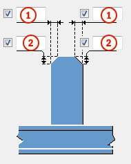
Horizontal chamfer dimension for the stanchions. |
|
2 |
Vertical chamfer dimension for the stanchions. |
Gap
|
Option |
Description |
|---|---|
|
Top rail parts gap Midd. rail parts gap Bott. rail parts gap |
Select whether a gap is created between the rail parts. By default, no gap is created. |
Gap between parts
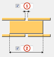
|
Description |
|
|---|---|
|
1 |
Size of the gap between two consecutive rail parts. |
|
2 |
Length of the continuous profile. |
Assembly
|
Option |
Description |
|---|---|
|
Create assembly |
Select which part of the railing is the main part of the assembly. By default, no assembly is created.
|
Rails tab
Use the Rails tab to control the profiles, bending cuts, and connections for the top and the bottom rails.
Rail and closure profiles
|
Option |
Description |
|---|---|
|
Top rail profile |
Define the top rail profile by selecting it from the profile catalog. Top rail is always created. |
|
Bottom rail profile |
Define the bottom rail profile by selecting it from the profile catalog. Bottom rail is always created. |
|
Start closure |
Define the start closure by selecting it from the profile catalog. By default, the Start closure profile is the same as the Top rail profile. |
|
End closure |
Define the end closure by selecting it from the profile catalog. By default, the End closure profile is the same as the Top rail profile. |
|
Option |
Description |
Default |
|---|---|---|
|
Pos_No |
Prefix and start number for the part position number. Some components have a second row of fields where you can enter the assembly position number. |
The default part start number is defined in the Components settings in . |
|
Material |
Material grade. |
The default material is defined in the Part material box in the Components settings in . |
|
Name |
Name that is shown in drawings and reports. |
|
|
Class |
Part class number. |
|
|
Finish |
Describes how the part surface has been treated. |
Closure bending cuts
|
Option |
Description |
|---|---|
|
|
Default No cut AutoDefaults can change this option. |
|
|
No cut No cut is created near the corner. |
|
|
Both side cuts The rail corner is cut at the left and the right side. The dimensions for the cut are defined on the Bends tab. |
|
|
Middle corner cut The rail corner is cut in the middle. |
|
|
Mitre corner cut The rail corner is cut by a plane on the bisecting line. |
|
|
Left side cut The rail corner is cut at the left side. The dimensions for the cut are defined on the Bends tab. |
|
|
Right side cut The rail corner is cut at the right side. The dimensions for the cut are defined on the Bends tab. |
Cut position of the rails
Define the cut position for the top and the bottom rails and for the closure types 1 and 4.
|
Option |
Description |
|---|---|
|
|
Default Closure near side cut AutoDefaults can change this option. |
|
|
Closure near side cut The rail passes through the first or the last stanchion and is cut at its surface. The closure is cut at the near side surface of the stanchion, without intersecting it. |
|
|
Middle stanchion cut The rail passes through the first or the last stanchion and is cut at its middle line. The closure is cut at the middle line of the stanchion, intersecting it. |
|
|
Closure far side cut The rail is cut at the surface of the stanchion, without intersecting it. The closure is cut at the other far side surface of the stanchion, intersecting it. |
Cut position for the other bending
Define the cut position for the other bendings than the corners of the closures.
|
Option |
Description |
|---|---|
|
|
Default No cut is created. AutoDefaults can change this option. |
|
|
No cut is created. |
|
|
Both side cuts The rail bending is cut at the left and the right side. The dimensions for the cut are defined on the Bends tab. |
|
|
Middle corner cut The rail bending is cut in the middle. |
|
|
Mitre corner cut The rail bending is cut by a plane on the bisecting line. |
Top rail position / Bottom rail position
Define the horizontal railing position.
By default, the Middle option is used.
Top rail rotation / Bottom rail rotation
Define the profile rotation for all horizontal rails.
|
Option |
Description |
|---|---|
|
|
Default Type 1 AutoDefaults can change this option. |
|
|
Type 1 |
|
|
Type 2 |
|
|
Type 3 |
|
|
Type 4 |
|
|
Type 5 |
|
|
Type 6 |
|
|
Type 7 |
|
|
Type 8 |
Top rail and bottom rail connection properties
| Option | Description |
|---|---|
|
Top rail connection, Bottom rail connection |
Select whether to use a system or a custom component to connect the top and bottom rails to the stanchions. |
|
Component |
Select a system or custom component from the Applications & components catalog. |
|
Attribute file |
Select an attribute file for the component. |
|
Up direction |
Select the up direction. |
|
Rotation |
Select the rotation for the selected component. |
|
Rotation value |
Enter the rotation value. |
Middle Rails tab
Use the Middle Rails tab to control the horizontal middle rails.
Rail profile
|
Option |
Description |
|---|---|
|
1 2 3 4 |
Define the middle rail profile by selecting it from the profile catalog. By default, the size of middle rail profile is the same as the size of the top rail profile. The default name is MIDDLE RAIL. |
|
Option |
Description |
Default |
|---|---|---|
|
Pos_No |
Prefix and start number for the part position number. Some components have a second row of fields where you can enter the assembly position number. |
The default part start number is defined in the Components settings in . |
|
Material |
Material grade. |
The default material is defined in the Part material box in the Components settings in . |
|
Name |
Name that is shown in drawings and reports. |
|
|
Class |
Part class number. |
|
|
Finish |
Describes how the part surface has been treated. |
Middle rail type
|
Option |
Description |
|---|---|
|
Middle rail profiles |
Number of rails and the rail profile used for middle rails. For example, 3*2 creates three horizontal middle rails, with the profile defined in profile 2. For example, 2*2 1 creates two horizontal middle rails, with the profile defined in profile 2 and one or more rails (depending of the number of rails needed), with the profile defined in profile 1. For example, 3 creates horizontal middle rails with the profile defined in profile 3. The number of rails is defined by the number set for the horizontal or vertical middle rails. By default, only rails with profile from profile 1 are created. |
|
Option |
Description |
|---|---|
|
|
Default Creates horizontal middle rails. AutoDefaults can change this option. |
|
|
Creates horizontal middle rails. |
|
|
Creates vertical middle rails (pickets) defined on the Vertical Rails tab. |
|
|
Creates panels. |
Middle rail position
Define the horizontal railing position.
By default, the Middle option is used.
Middle rail rotation
Define the profile rotation for all horizontal rails.
| Option | Description |
|---|---|
|
|
Default Type 1 AutoDefaults can change this option. |
|
|
Type 1 |
|
|
Type 2 |
|
|
Type 3 |
|
|
Type 4 |
|
|
Type 5 |
|
|
Type 6 |
|
|
Type 7 |
|
|
Type 8 |
Cut position for the bending
|
Option |
Description |
|---|---|
|
|
Default No cut AutoDefaults can change this option. |
|
|
No cut No cut is created. |
|
|
Both side cuts The rail bending is cut at the left and right side. The dimensions for the cut are defined on the Bends tab. |
|
|
Middle corner cut The rail bending is cut in the middle. |
|
|
Mitre corner cut The rail bending is cut by a plane on the bisecting line. |
Horizontal middle rail extension
|
Option |
Description |
|
|---|---|---|
|
|
|
Default No extension AutoDefaults can change this option. |
|
|
|
No extension The middle rail ends at the inside stanchion surface, without intersecting the stanchion. |
|
|
|
Pass through stanchion The middle rail ends at the outside stanchion surface, intersecting the stanchion. |
|
|
|
Horizontal extension The middle rails are extended inside the closure by a horizontal value. If the railing is skew, the extension is bent according to the closure dimensions. The rail can be shortened by entering a negative value in the box 3. |
|
|
|
Horizontal and skew extension The middle rails are extended by two horizontal dimensions. 3 is for the horizontal rail length and 4 is for the skew rail length. |
Closure bend cuts
This section is not active if you have set the middle rail type to vertical middle rails.
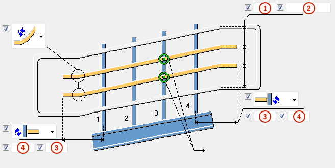
|
Description |
|
|---|---|
|
1 |
Number of horizontal middle rails. |
|
2 |
Spacing between the horizontal middle rails. |
|
3 |
Length of the middle rail horizontal extension inside the closure. The rail can be shortened by entering a negative value. Use this box when the horizontal middle rail extension is set to horizontal extension. |
|
4 |
Length of the middle rail horizontal and skew extension. The middle rails are extended by two horizontal dimensions. 3 is for the horizontal rail length and 4 is for the skew rail length. Use this box when the horizontal middle rail extension is set to horizontal and skew extension. |
Middle rail connection properties
| Option | Description |
|---|---|
|
Middle rail connection |
Select whether to use a system or custom component to connect the middle rails to the stanchions. |
|
Component |
Select a system or custom component from the Applications & components catalog. |
|
Attribute file |
Select an attribute file for the component. |
|
Up direction |
Select the up direction. |
|
Rotation |
Select the rotation for the selected component. |
|
Rotation value |
Enter the rotation value. |
|
Connect to |
Select whether one rail or two rails are connected to stanchions. |
Grab rail
Grab rail can be a single middle rail that is vertically and horizontally offset from the top rail. You can use a system or a custom component to connect the rail to stanchions. You can also select the end of the grab rail. If the grab rail comes from a skew stringer, you can extend the grab rail with skew and horizontal dimensions.

To create a grab rail:
-
On the Picture tab, offset the middle rails from the stanchions.

-
On the Rails tab, set the profile for top and bottom rails to 0 so that those rails are not created.

-
On the Middle Rails tab, set the number of horizontal rails to 1 and adjust the spacing for the handrail.
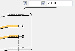
-
If you want to extend the end of the grab rail and have a horizontal part, select the horizontal and skew extension option on the Middle Rails tab, and enter the skew and horizontal distances.

-
Create the custom seam.
Pick the points on the outer extension of the main and secondary parts.
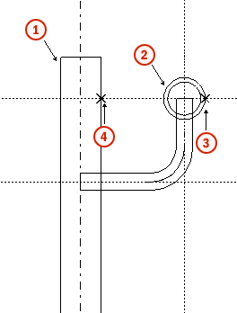
Description
1
Main part
2
Secondary part
3
First picked point
4
Second picked point
-
Save the standard properties for the custom seam.
-
On the Middle Rails tab, use the custom seam name and properties and set the component direction.
Vertical Rails tab
Use the Vertical Rails tab to control the vertical rails (pickets). The options on the Vertical Rails tab are active only if you have set the middle rail type to vertical middle rails on the Middle Rails tab.
Pickets
|
Option |
Description |
|
|---|---|---|
|
|
|
Default Pickets are not created inside the closure. AutoDefaults can change this option. |
|
|
|
Pickets are not created inside the closure. |
|
|
|
Pickets are created inside the closure when you use the closure type 1 or 4. |
Connection type between the pickets and the top and bottom rails
|
Option |
Description |
|---|---|
|
|
Default None AutoDefaults can change this option. |
|
|
None The pickets are created from the top rail center to the bottom rail center. |
|
|
Fitted The pickets are fitted at the creation points by a plane that follows the slope of the horizontal rails. |
|
|
Part cut The pickets are cut on both sides by the horizontal rail profiles. |
|
|
Connection The pickets are connected to the top and bottom rail with a system connection. |
Picket spacing
|
Option |
Description |
|---|---|
|
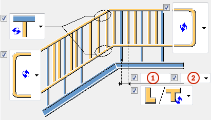
1 |
Picket spacing between two consecutive stanchions. |
|
2 |
Spacing type. By default, the equal spacing option is used.
|
Chamfer dimensions
|
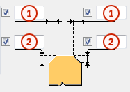
Description |
|
|---|---|
|
1 |
Horizontal chamfer dimension for the pickets. |
|
2 |
Vertical chamfer dimension for the pickets. |
Profile rotation
Define the profile rotation for all vertical rails.
|
Option |
Description |
|---|---|
|
|
Default |
|
|
Type 1 |
|
|
Type 2 |
|
|
Type 3 |
|
|
Type 4 |
|
|
Type 5 |
|
|
Type 6 |
|
|
Type 7 |
|
|
Type 8 |
Connection properties
|
Option |
Description |
|---|---|
|
Vertical rail top joint |
Define the number of the component that connects the pickets to the top rail by selecting it from the component catalog. You cannot use a custom component. Select also an attribute file for the component. |
|
Vertical rail bottom joint |
Define the number of the connection that connects the pickets to the bottom rail by selecting it from the component catalog. You cannot use a custom component. Select also an attribute file for the component. |
Panels tab
Use the Panels tab to create panels between the stanchions. No other vertical or horizontal rails are created when the panels are created. The options on the Panels tab are active only if you have set the middle rail type to panels on the Middle Rails tab. You can use custom seams to create the middle panels and custom details to create the closure panels.
Panel properties
|
Option |
Description |
|---|---|
|
Part name/Joint no. |
Define the number of the custom component used in panel creation by selecting it from the component catalog. |
|
Attribute file |
Select an attribute file for the custom component. |
|
Seam dir. |
Define the seam direction. |
Panel type
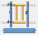
For custom details the numbers in the images correspond to the following parts:
|
Number |
Part |
|---|---|
|
1 |
First stanchion, which is the main part of the detail. |
|
2 |
Point at the top of the first stanchion, which is the first input point of the detail. |
|
3 |
Point at the bottom of the first stanchion, which is the second input point of the detail. |
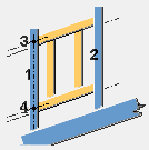
For custom seams the numbers in the images correspond to the following parts:
|
Number |
Part |
|---|---|
|
1 |
First stanchion, which is the main part of the seam. |
|
2 |
Second stanchion, which is the secondary part of the seam. |
|
3 |
Point at the top of the first stanchion, which is the first input point of the seam. |
|
4 |
Point at the bottom of the first stanchion, which is the second input point of the seam. |
|
Option |
Description |
|---|---|
|
|
Left closure panel Use a custom detail to create the panel. The panel connects to one stanchion only. |
|
|
First panel Use a custom seam to create the panel. The panel can be of different size than the rest of the panels. |
|
|
Last panel Use a custom seam to create the panel. The panel can be of different size than the rest of the panels. |
|
|
Right closure panel Use a custom detail to create the panel. The panel connects to one stanchion only. |
|
|
Regular horizontal panel Use a custom seam to create the panel. |
|
|
Regular skew panel Use a custom seam to create the panel. |
|
|
Horizontal panel, skew junction (bottom) Use a custom seam to create the panel. |
|
|
Horizontal panel, skew junction (top) Use a custom seam to create the panel. |
Bends tab
Use the Bends tab to set the bending cut position on the rails and the profiles for the bent rails parts.
Bend profile
|
Option |
Description |
|---|---|
|
Bend |
Define the bend rail profile by selecting it from the profile catalog. Created only if you have set the closure bend cuts to both side cut, left side cut, or right side cut on the Rails tab. |
|
90 degree |
Define the rail profile by selecting it from the profile catalog. Created only if you have set the cut position for the bending to both side cut on the Rails or Middle Rails tab. |
|
Option |
Description |
Default |
|---|---|---|
|
Pos_No |
Prefix and start number for the part position number. Some components have a second row of fields where you can enter the assembly position number. |
The default part start number is defined in the Components settings in . |
|
Material |
Material grade. |
The default material is defined in the Part material box in the Components settings in . |
|
Name |
Name that is shown in drawings and reports. |
|
|
Class |
Part class number. |
|
|
Finish |
Describes how the part surface has been treated. |
Bend dimensions
|
Option |
Description |
Default |
|---|---|---|
|
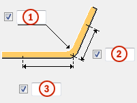
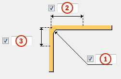
1 |
Bending radius for the rail parts. |
50 mm |
|
2 |
Cut distance along the rails on the right side of the bending. |
75 mm |
|
3 |
Cut distance along the rails on the left side of the bending. |
75 mm |
Welds
Click the link below to find out more:

