Formwork placing tools - Walls: configuration
You can set up your own configuration files for Formwork placings tools - Walls.
The configuration is done by using comma separated files (.csv), which can be edited with Microsoft Excel or any standard text editor. Each separate formwork sub-tool component has its own configuration file.
The configuration files can be located in any of the system folders, or in the sub-folder called Formwork tools in the current model folder.
Example configuration files are located in the ...\Trimble\Tekla Structures\<version>\Environments\common\system\CIP\Formwork folder.
The configuration files are typically named by the formwork supplier and/or the product families. There can be any number of files, and the files are identified with a specific suffix. Each of the files controls one of the sub-tools in the component. The files contain varying number of columns.
Use the following configuration files for Formwork placings tools - Walls to set up
-
panels: xxxx.FormworkTools.Panels.csv
-
ties for the tie placing tool: xxxx.FormworkTools.Ties.csv
-
tie spacers placed by the tie placing tool: xxxx.FormworkTools.TieSpacers.csv
-
clamps: xxxx.FormworkTools.Clamps.csv
-
braces: xxxx.FormworkTools.Braces.csv
-
pouring platforms: xxxx.FormworkTools.Platforms.csv
-
walers: xxxx.FormworkTools.Walers.csv
-
conditions (corners, pilasters and bulkheads): xxxx.FormworkTools.Conditions.csv
-
fillers: xxxx.FormworkTools.Fillers.csv
Accessories in formwork placing tools
You can set up any formwork accessory to be created as a beam, an item, or as a custom part. For beams and items you can additionally set up any of the beam or items properties or UDAs either in the configuration file by adding new columns, or as property files.
Each configuration file contains a header row and data rows. The header row is the first row that is not a comment row, and it gives the configuration parameter names (column name). Each data row gives one product and defines the parameters used when placing the beam, item or custom part.
In addition to header row and data rows the file can contain comment rows. A comment row is any row starting with text //.
You can define the distance unit by adding a row:
DISTANCE_UNIT=MM
When the distance unit is defined using the above setting, all distance values can be given as decimal values in the specified units. The supported units are: MM, DN, CM, M, INCH, FEET.
The following accessories are available for different Formwork placings tools - Walls product types. For example, for a brace you can specify Brace, Bracket1 and Bracket2 accessories.
| Product type | Accessory |
|---|---|
|
Panel |
Panel |
|
Tie |
Part1, the actual tie rod Part2, the front lock Part3, the back lock |
|
Tie spacer |
SpacerTube StartCone EndCone |
|
Clamp |
Part1 |
|
Brace |
Brace Bracket1 Bracket2 |
|
Platform |
Part1 Part2 |
|
Waler |
Beam Clamp1 Clamp2 |
|
Filler |
Timber Stud Plywood Part1 Part2 - Part10 |
Common configuration parameter fields
To configure the accessories in any of the formwork product types, define the following fields in the .csv configuration file.
The text [Accessory] in the following table denotes the accessory in question.
| Column name in the .csv file | Description |
|---|---|
|
[Accessory].Profile [Accessory].Item [Accessory].CustomPart |
Formwork placing tools can place either beams, items, or custom parts to the model. If all products are of the same model object type you can use one of the three field names and give the corresponding data value. The field name specifies the model object default type but you can also override the model object type by adding the prefix BEAM:, ITEM: or CUSTOMPART: for the actual value. The actual value for BEAM: is a valid profile string, for ITEM: a valid item shape name, and for CUSTOMPART: a valid custom part name. |
|
[Accessory].Attributes |
Saved property file used to set either part, item or custom part properties. |
|
[Accessory].Name |
Name of the part or the item, or the Name property of the custom part. |
|
[Accessory].Class |
Class of the part or the item, or the Class property of the custom part. |
|
[Accessory].Material |
Material of the part or the item, or the Material property of the custom part. |
|
[Accessory].AssPrefix |
Part or item numbering assembly prefix, or the AssPrefix property of the custom part. |
|
[Accessory].AssStartNo |
Part or item assembly start number, or the AssStartNo property of the custom part. |
|
[Accessory].PartPrefix |
Part or item numbering part prefix, or the PartPrefix property of the custom part. |
|
[Accessory].PartStartNo |
Part or item part start number, or the PartStartNo property of the custom part. |
|
[Accessory].Finish |
Finish of the part or the item, or the Finish property of the custom part. |
|
[Accessory].InputOrder |
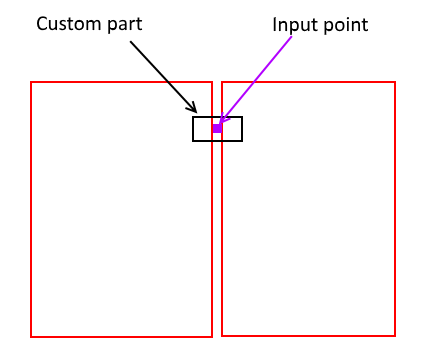
Set the final locations of the input points in relation to the default generic start and end points. The possible values are:
Note that if the .csv file does not contain any value, the default value StartEnd is used.
|
|
[Accessory].PlanePosition |
This is Position in plane when the beam, item, or custom part is inserted in the plane view. The options are MIDDLE, LEFT, and RIGHT. |
|
[Accessory].PlaneOffset |
Offset on plane. The default value is 0. |
|
[Accessory].Rotation |
This is Rotation when the custom part is inserted in the plane view. The options are FRONT, TOP, BACK, and BELOW. |
|
[Accessory].RotationOffset |
Rotation offset in degrees. The default value is 0. |
|
[Accessory].DepthPosition |
This is Position at depth when the beam, item, or custom part is inserted in the plane view. The options are MIDDLE, FRONT, and BEHIND. |
|
[Accessory].DepthOffset |
Offset at depth. The default value is 0. |
|
[Accessory].StartOffset |
Offset of the actual start point from the generic start point in the local coordinate system. Give the offset as x, y and z values that are separated by a space or a colon, and enclosed in parentheses (0 100 0). If no value is given, a zero offset (0 0 0) is used. |
|
[Accessory].EndOffset |
Offset of the actual end point from the generic end point in the local coordinate system. Give the offset as x, y and z values that are separated by a space or a colon, and enclosed in parentheses (0 100 0). If no value is given, a zero offset (0 0 0) is used. |
|
[Accessory].UDA.XXXXXX |
Define additional UDA values applied to the model objects. You can introduce as many UDA values as needed. Note that the UDA name (XXXXX) must be the internal name, not the localized name shown in the user interface. |
Configure the panel placing tool
.FormworkTools.Panels.csv
Add or modify one row for each panel.
The configuration of all accessories that can be added to panels is done in the local coordinate system of the panel. The origin of the panel is located at the center point of the panel.

| Definition | Description |
|---|---|
|
Supplier |
Supplier name, this is typically the same for all rows. The name is shown in the Formwork supplier list. |
|
Family |
Family name, which is shown in the Product family list. |
|
Name |
Unique panel name, which is shown in the Formwork panel list. |
|
PanelName |
Name of the custom part that will be inserted in the model. |
|
PanelAttributes |
Property file saved in the component dialog box to be used when the custom part will be inserted in the model. |
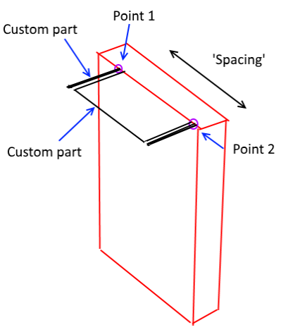
|
PanelInputOrder |
Define the orientation of the custom part panels by specifying where the start and end handles of the custom part will go. Set the final locations of the input points in relation to the default generic start and end points. The possible values are:
Note that if the .csv file does not contain any value, the default value StartEnd is used.
|
|
PanelPlanePosition |
Use the following position values to define the custom part's position, offset and rotation in relation to the custom part start and end points. Use Position in plane to insert the custom part in plane view. The options are MIDDLE, LEFT, and RIGHT. |
|
PanelPlaneOffset |
Offset on plane. The default value is 0. |
|
PanelRotation |
Use Rotation to insert the custom part in the plane view. The options are FRONT, TOP, BACK, and BELOW. |
|
PanelRotationOffset |
Rotation offset in degrees. The default value is 0. |
|
PanelDepthPosition |
Use Position at depth to insert the custom part in plane view. The options are MIDDLE, FRONT, and BEHIND. |
|
PanelDepthOffset |
Offset at depth. The default value is 0. |
|
PanelStartOffset |
PanelStartOffset and PanelEndOffset change the location of the actual start and end handles of the custom part. PanelStartOffset is the offset of the actual start point from the generic start point in the local coordinate system. Give the offset as x, y and z values that are separated by a space or a colon, and enclosed in parentheses (0 100 0). If no value is given, a zero offset (0 0 0) is used. |
|
PanelEndOffset |
PanelEndOffset is the offset of the actual end point from the generic end point in the local coordinate system. Give the offset as x, y and z values that are separated by a space or a colon, and enclosed in parentheses (0 100 0). If no value is given, a zero offset (0 0 0) is used. |
|
HeightProperty |
Name of the height property in the custom part. If the height is fixed, this is empty. |
|
HeightValue |
Height of the panel. Note that the height value is read from the .csv file. |
|
WidthProperty |
Name of the width property in the custom part. If the width is fixed, this is empty. |
|
WidthValue |
Width of the panel. Note that the width value is read from the .csv file. |
|
ThicknessProperty |
Name of the thickness property in the custom part. If the thickness is fixed, this is empty. |
|
ThicknessValue |
Thickness of the panel. Note that the thickness value is read from the .csv file. |
|
TieX |
TieX specifies the x locations of the ties. Values must be enclosed in parentheses () and separated by spaces. |
|
TieY |
TieY specifies the y locations of the ties. Values must be enclosed in parentheses () and separated by spaces. |
|
TiePickX TiePickY or TiePickXY |
Define the possible x and y locations of the ties when placing and picking a single tie. You can either specify the x and y values separately in two value fields to define a regular grid of locations, or if your panels require an irregular pattern, you can specify a list of x and y value pairs. Always define the x and y values in two separate fields (TiePickX and TiePickY), or x and y value pairs in one field (TiePickXY). Values must be enclosed in parentheses () and separated by spaces. |
|
ClampX |
ClampX specifies the x locations of the clamps at the horizontal top/bottom edges. Values must be enclosed in parentheses () and separated by spaces. |
|
ClampY |
ClampY specifies the y locations of the clamps at the vertical left/right edges. Values must be enclosed in parentheses () and separated by spaces. |
|
ClampPickX ClampPickY or ClampPickXY |
Define the possible x and y locations of the clamps when placing and picking a single clamp. You can either specify the x and y values separately in two value fields to define a regular grid of locations, or if your panels require an irregular pattern, you can specify a list of x and y value pairs. Always define the x and y values in two separate fields (ClampPickX and ClampPickY), or x and y value pairs in one field (ClampPickXY). Values must be enclosed in parentheses () and separated by spaces. |
|
BraceX BraceY or BraceXY |
Define the preset pattern for the braces. You can either specify the x and y values separately in two value fields to define a regular grid of locations, or if your panels require an irregular pattern, you can specify a list of x and y value pairs. Always define the x and y values in two separate fields (BraceX and BraceY), or x and y value pairs in one field (BraceXY). Values must be enclosed in parentheses () and separated by spaces. |
|
BraceTiltedX BraceTiltedY or BraceTiltedXY |
Define the preset pattern for the braces when the panel is tilted. You can either specify the x and y values separately in two value fields to define a regular grid of locations, or if your panels require an irregular pattern, you can specify a list of x and y value pairs. Always define the x and y values in two separate fields (BraceTiltedX and BraceTiltedY), or x and y value pairs in one field (BraceTiltedXY). Values must be enclosed in parentheses () and separated by spaces. |
|
BracePickX BracePickY or BracePickXY |
Define the possible x and y locations of the braces when placing and picking a single brace in a panel. You can either specify the x and y values separately in two value fields to define a regular grid of locations, or if your panels require an irregular pattern, you can specify a list of x and y value pairs. Always define the x and y values in two separate fields (BracePickX and BracePickY), or x and y value pairs in one field (BracePickXY). Values must be enclosed in parentheses () and separated by spaces. |
|
BraceTiltedPickX BraceTiltedPickY or BraceTiltedPickXY |
Define the possible x and y locations of the braces when placing and picking a single brace in a tilted panel. You can either specify the x and y values separately in two value fields to define a regular grid of locations, or if your panels require an irregular pattern, you can specify a list of x and y value pairs. Always define the x and y values in two separate fields (BraceTiltedPickX and BraceTiltedPickY), or x and y value pairs in one field (BraceTiltedPickXY). Values must be enclosed in parentheses () and separated by spaces. |
|
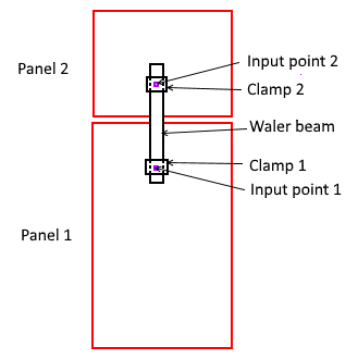
WalerEdgeOffset |
Offset of the waler input point (=location of the clamp 1 and/or clamp 2) from the panel edge when the walers are placed automatically.
|
|
WalerX |
X locations used for placing walers automatically at horizontal top/bottom edges. The vertical (y) location is defined by WalerEdgeOffset from the top/bottom edge. Values must be enclosed in parentheses () and separated by commas or spaces. |
|
WalerY |
Y locations used for placing walers automatically at vertical left/right edges. The horizontal (x) location is defined by WalerEdgeOffset from left/right edge. Values must be enclosed in parentheses () and separated by commas or spaces. |
|
WalerPickX |
Define the possible x locations of the walers when placing and picking a single waler. Values must be enclosed in parentheses () and separated by commas or spaces. |
|
WalerPickY |
Define the possible y locations of the walers when placing and picking a single waler. Values must be enclosed in parentheses () and separated by commas or spaces. |
Configure the tie placing tool
xxxx.FormworkTools.Ties.csv
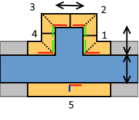
A generic tie consists of three custom components: a bolt that usually goes through the wall, and two locks on both sides of the formwork.
Add or modify one row for each tie.
| Definition | Description |
|---|---|
|
Supplier |
Supplier name, which is typically the same for all rows. The name is shown in the Formwork supplier list. |
|
Family |
Family name, which is shown in the Product family list. |
|
Name |
Tie name, which is shown in the Tie type list. This name can be unique, or multiple tie configurations may have the same name. When multiple tie configurations have the same name, the tool automatically selects the first suitable tie based on the wall thickness. |
|
MaxLength |
Maximum length of the tie, measured from outer faces of the two formwork panels on opposite sides. |
|
LengthProperty |
If the tie custom part is parametric and has a parameter controlling the effective length, this is the name of the Length property. |
|
Part1Name |
Name of the custom part 1 that will be inserted in the model (=bolt). |
|
Part1Attributes |
Property file saved in the component dialog box to be used when the custom part is inserted in the model. |
|
Part1PlanePosition |
This is Position in plane when the custom part is inserted in the face view of the main formwork panel. |
|
Part1PlaneOffset |
This is Offset on plane value when the custom part is inserted in the face view of the main formwork panel. |
|
Part1Rotation |
This is Rotation when the custom part is inserted in the face view of the main formwork panel. |
|
Part1RotationOffset |
This is Rotation offset when the custom part is inserted in the face view of the main formwork panel. |
|
Part1DepthPosition |
This is Position at depth when the custom part is inserted in the face view of the main formwork panel. |
|
Part1DepthOffset |
This is Offset at depth when the custom part is inserted in the face view of the main formwork panel. |
|
Part1StartOffset |
Offset of the first insertion point in relation to Input point 1. |
|
Part1EndOffset |
Offset of the first insertion point in relation to Input point 2. |
|
Part2Name |
Name of the custom part 2, which typically is the lock on the front side of the main formwork panel. |
|
Part2Attributes |
Property file saved in the component dialog box to be used when the custom part will be inserted in the model. |
|
Part2StartOffset |
Offset of the second insertion point in relation to Input point 1. |
|
Part2EndOffset |
Location of the second insertion point in relation to the Input point 1. |
|
Part2... |
For custom part 2, you can specify the same fields as for custom part 1. |
|
Part3Name |
Name of the custom part 3, which typically is the lock on the back side of the main formwork panel. |
|
Part3Attributes |
Property file saved in the component dialog box to be used when the custom part will be inserted in the model. |
|
Part3StartOffset |
Offset of the first insertion point in relation to Input point 2. |
|
Part3EndOffset |
Location of the second insertion point in relation to the Input point 2. |
|
Part3... |
For custom part 3, you can specify the same fields as for custom part 1. |
Configure the spacers for the tie placing tool
xxxx.FormworkTools.TieSpacers.csv
A generic tie spacer consists of three custom components: a tube that usually goes through the wall, and two optional cones at each side of the wall.
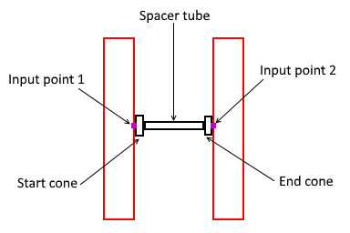
Add or modify one row for each tie spacer.
| Definition | Description |
|---|---|
|
Supplier |
Supplier name, which is typically the same for all rows. The name is shown in the Formwork supplier list. |
|
Family |
Family name, which is shown in the Product family list. |
|
Name |
Spacer name, which is shown in the Spacer name list. This name can be unique, or multiple tie spacer configurations may have the same name. When multiple tie spacer configurations have the same name, the tool automatically selects the first suitable tie spacer based on the wall thickness. |
|
MinLength |
Minimum possible length of the tube, measured from the inner faces of the two formwork panels on the opposite sides. |
|
MaxLength |
Maximum possible length of the tube, measured from the inner faces of the two formwork panels on the opposite sides. |
|
LengthProperty |
If the tie spacer custom part is parametric and has a parameter controlling the effective length, this is the name of the Length property. |
|
SpacerTubeName |
Name of the custom part (=tube). |
|
SpacerTubeAttributes |
Property file saved in the component dialog box to be used when the custom part will be inserted in the model. |
|
SpacerTubePlanePosition |
This is Position in plane when the custom part is inserted in the face view of the main formwork panel. |
|
SpacerTubePlaneOffset |
This is Offset in plane when the custom part is inserted in the face view of the main formwork panel. |
|
SpacerTubeRotation |
This is Rotation when the custom part is inserted in the face view of the main formwork panel. |
|
SpacerTubeRotationOffset |
This is Rotation offset when the custom part is inserted in the face view of the main formwork panel. |
|
SpacerTubeDepthPosition |
This is Position in depth when the custom part is inserted in the face view of the main formwork panel. |
|
SpacerTubeDepthOffset |
This is Offset in depth when the custom part is inserted in the face view of the main formwork panel. |
|
SpacerTubeStartOffset |
Offset of the first insertion point in relation to Input point 1. |
|
SpacerTubeEndOffset |
Offset of the first insertion point in relation to Input point 2. |
|
StartConeName |
Name of the custom part, which typically is the cone on the front side of the main formwork panel. |
|
StartConeAttributes |
Property file saved in the component dialog box to be used when the custom part is inserted in the modell. |
|
StartConeStartOffset |
Offset of the first insertion point in relation to Input point 1. |
|
StartConeEndOffset |
Location of the second insertion point in relation to the Input point 1. |
|
StartCone... |
For custom part 2, you can specify the same fields as for custom part 1. |
|
EndConeName |
Name of the custom part which typically is the cone on the back side of the main formwork panel. |
|
EndConeAttributes |
Property file saved in the component dialog box to be used when the custom is be inserted in the model. |
|
EndConeStartOffset |
Offset of the first insertion point in relation to Input point 2. |
|
EndConeEndOffset |
Location of the second insertion point in relation to the Input point 2. |
|
EndCone... |
For custom part 3, you can specify the same fields as for custom part 1. |
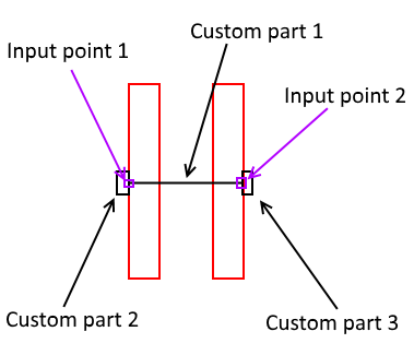
Configure the clamp placing tool
xxxx.FormworkTools.Clamps.csv
The generic clamp contains one custom part. The input points are at the edges of the two panels and thus the clamp can be parametric in terms of the filler space, if needed.
Note that to create the brackets with some additional bolts or locks, you need to make a new custom part containing both the bracket and all necessary fittings:
| Definition | Description |
|---|---|
|
Supplier |
Supplier name, which is typically the same for all rows. The name is shown in the Formwork supplier list. |
|
Family |
Family name, which is shown in the Product family list. |
|
Name |
Unique clamp name. |
|
CenterInput |
When YES, the first insertion point is in the middle of the seam of the two panels. If the value is NO, the insertion points are offset from the edge of the panels. |
|
FillerGapProperty |
If the clamp custom part is parametric, and the parameter can adjust the gap between two panels, this is the name of that parameter. This field is empty if the clamp is not parametric. |
|
MaxFillerGap |
This value is used when clamps or walers are added automatically along with a formwork filler. If the free space (=width of the filler) is less or equal to the given MaxFillerGap, clamps will be inserted. If the free space is greater than the given MaxFillerGap, walers will be inserted. |
|
Part1Name |
Name of the clamp custom part 1. |
|
Part1Attributes |
Property file saved in the component dialog box to be used when the custom part is inserted in the model. |
|
Part1PlanePosition |
This is Position in plane when the custom part is inserted in the face view of the main formwork panel. |
|
Part1PlaneOffset |
This is Offset in plane when the custom part is inserted in the face view of the main formwork panel. |
|
Part1Rotation |
This is Rotation when the custom part is inserted in the face view of the main formwork panel. |
|
Part1RotationOffset |
This is Rotation offset when the custom part is inserted in the face view of the main formwork panel. |
|
Part1DepthPosition |
This is Position in depth when the custom part is inserted in the face view of the main formwork panel. |
|
Part1DepthOffset |
This is Offset in depth when the custom part is inserted in the face view of the main formwork panel. |
|
Part1StartOffset |
Offset of the first insertion point in relation to Input point 1. |
|
Part1EndOffset |
Location of the second insertion point in relation to the Input point 1. |
Configure the brace placing tool
xxxx.FormworkTools.Braces.csv
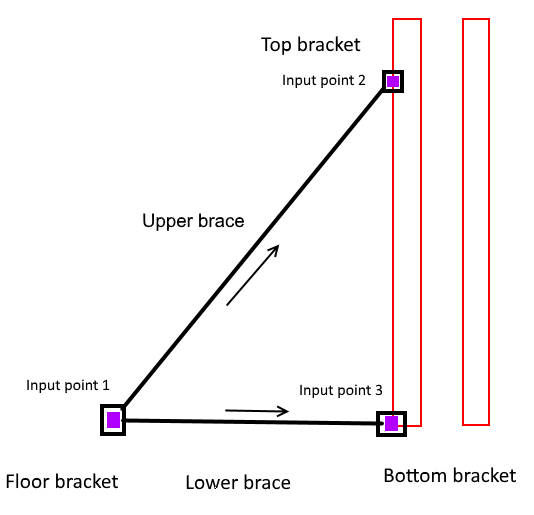
A generic brace may consists of five custom parts, which are inserted in the model by using three input points. You can select the upper and lower braces separately. In the brace configuration file, the upper and lower braces are defined separately; they both have own rows.
| Definition | Description |
|---|---|
|
Supplier |
Supplier name, which is typically the same for all rows. The name is shown in the Formwork supplier list. |
|
Family |
Family name, which is shown in the Product family list. |
|
Name |
Brace name which is shown in the list. If you have several rows with the same name, the tool automatically selects the suitable brace based on the minimum and maximum length. |
|
Type |
Type of the brace. The options are Upper or Lower. |
|
MinLength |
Minimum possible length of the main brace measured from Input point 1 to Input point 2. |
|
MaxLength |
Maximum possible length of the main brace measured from Input point 1 to Input point 2. |
|
LengthProperty |
If the brace custom part is parametric and has a parameter controlling the effective length, this is the name of the Length property. At insertion it will get the actual length value between Input point 1 and Input point 2. |
|
BraceName |
Name of the custom part for the upper or lower brace which will be inserted into the model. |
|
BraceAttributes |
Property file saved in the component dialog box to be used when the custom part is inserted in the model. |
|
BracePlanePosition |
This is Position in plane when the custom part is inserted in plane view. |
|
BracePlaneOffset |
This is Offset in plane when the custom part is inserted in plane view. |
|
BraceRotation |
This is Rotation when the custom part is inserted in plane view. |
|
BraceRotationOffset |
This is Rotation offset when the custom part is inserted in plane view. |
|
BraceDepthPosition |
This is Position in depth when the custom part is inserted in plane view. |
|
BraceDepthOffset |
This is Offset in depth when the custom part is inserted in plane view. |
|
BraceStartOffset |
Offset of the first insertion point in relation to Input point 1. |
|
BraceEndOffset |
Offset of the first insertion point in relation to Input point 2. |
|
Bracket1Name |
Name of the custom part for the top bracket (upper brace) or bottom bracket (lower brace) which will be inserted into the model. |
|
Bracket1Attributes |
Property file saved in the component dialog box to be used when the custom part is inserted in the model. |
|
Bracket1StartOffset |
Offset of the first insertion point in relation to Input point 1. |
|
Bracket1EndOffset |
Location of the second insertion point in relation to the Input point 3. |
|
Bracket1... |
For custom part 2, you can specify the same fields as for custom part 1. |
|
Bracket2Name |
Name of the custom part for the floor bracket which will be inserted into the model. If both upper and lower brace have a definition for the bracket, the bracket defined for the lower brace will be created. |
|
Bracket2Attributes |
Property file saved in the component dialog box to be used when the custom part will be inserted in the model. |
|
Bracket2StartOffset |
Offset of the first insertion point in relation to Input point 2. |
|
Bracket2EndOffset |
Location of the second insertion point in relation to the Input point 2. |
|
Bracket2... |
For custom part 3, you can specify the same fields as for custom part 1. |
Configure the pouring platform placing tool
xxxx.FormworkTools.Platforms.csv
A generic pouring platform contains two custom parts, which are inserted in the model as a linear array of custom parts.
| Definition | Description |
|---|---|
|
Supplier |
Supplier name, which is typically the same for all rows. The name is shown in the Formwork supplier list. |
|
Family |
Family name, which is shown in the Product family list. |
|
Name |
Unique pouring platform name. |
|
Type |
The type of the platform (A or B). The length of the array is defined with start and end points of the platform. The custom part placing has two methods:
|
|
Length |
Effective length of one platform element. |
|
Width |
Width of the platform. |
|
Spacing |
Spacing between the custom parts in the array. |
|
Part1Name |
Name of the custom part 1. |
|
Part1Attributes |
Property file saved in the component dialog box to be used when the custom part is inserted in the model. |
|
Part1PlanePosition |
This is Position in plane when the custom part is inserted in the face view of the main formwork panel. |
|
Part1PlaneOffset |
This is Offset in plane when the custom part is inserted in the face view of the main formwork panel. |
|
Part1Rotation |
This is Rotation when the custom part is inserted in the face view of the main formwork panel. |
|
Part1RotationOffset |
This is Rotation offset when the custom part is inserted in the face view of the main formwork panel. |
|
Part1DepthPosition |
This is Position in depth when the custom part is inserted in the face view of the main formwork panel. |
|
Part1DepthOffset |
This is Offset in depth when the custom part is inserted in the face view of the main formwork panel. |
|
Part1StartOffset |
Offset of the first insertion point in relation to Input point 1. |
|
Part1EndOffset |
Offset of the first insertion point in relation to Input point 1. |
|
Part2Name |
Name of the custom part 2. |
|
Part2Attributes |
Property file saved in the component dialog box to be used when the custom part is inserted in the model. |
|
Part2StartOffset |
Offset of the first insertion point in relation to Input point 1. |
|
Part2EndOffset |
Location of the second insertion point in relation to the Input point 1. |
|
Part2... |
For custom part 2, you can specify the same fields as for custom part 1. |
Configure the waler placing tool
xxxx.FormworkTools.Walers.csv
A generic waler consists of three custom parts, the waler beam and two clamp devices. The generic input points are located in the outer face of the panel.
| Definition | Description |
|---|---|
|
Supplier |
Supplier name, which is typically the same for all rows. The name is shown in the Formwork supplier list. |
|
Family |
Family name, which is shown in the Product family list. |
|
Name |
Waler name, which is shown in the Waler type list. This name can be unique, or multiple tie waler configurations may have the same name. When multiple waler configurations have the same name, the tool automatically selects the shortest waler based on the actual length measured between the input points. Typically, you can specify the same waler with a unique name and a common name. This way you can select the common name and let the system select the waler based on the input length. By selecting the unique name you can force the usage of a certain waler configuration. |
|
MaxLength |
Maximum possible effective length of the waler, measured from the first input point to the second input points (=clamp locations), typically little less than the physical length. |
|
MinLength |
Minimum length of a waler with variable length. For fixed length walers, leave the value empty or give same value as for the maximum length. |
|
BeamName |
Name of the clamp custom part 1. |
|
BeamAttributes |
Property file saved in the component dialog box to be used when the custom part is inserted in the model. |
|
BeamPlanePosition |
This is Position in plane when the custom part is inserted in the face view of the main formwork panel. |
|
BeamPlaneOffset |
This is Offset in plane when the custom part is inserted in the face view of the main formwork panel. |
|
BeamRotation |
This is Rotation when the custom part is inserted in the face view of the main formwork panel. |
|
BeamRotationOffset |
This is Rotation offset when the custom part is inserted in the face view of the main formwork panel. |
|
BeamDepthPosition |
This is Position in depth when the custom part is inserted in the face view of the main formwork panel. |
|
BeamDepthOffset |
This is Offset in depth when the custom part is inserted in the face view of the main formwork panel. |
|
BeamStartOffset |
Offset of the first insertion point in relation to Input point 1. |
|
BeamEndOffset |
Location of the second insertion point in relation to the Input point 1. |
|
Clamp1Name |
Name of the clamp 1 custom part. |
|
Clamp1Attributes |
Property file saved in the component dialog box to be used when the custom part will be inserted in the model. |
|
Clamp1StartOffset |
Offset of the first insertion point in relation to Input point 1. |
|
Clamp1EndOffset |
Location of the second insertion point in relation to the Input point 1. |
|
Clamp1... |
For custom clamp 1, you can specify the same fields as for waler beam custom part. |
|
Clamp2Name |
Name of the clamp 2 custom part. |
|
Clamp2Attributes |
Property file saved in the component dialog box to be used when the custom part is inserted in the model. |
|
Clamp2StartOffset |
Offset of the first insertion point in relation to Input point 1. |
|
Clamp2EndOffset |
Location of the second insertion point in relation to the Input point 1. |
|
Clamp2... |
For custom clamp 2, you can specify the same fields as for waler beam and clamp 1 custom parts. |
Configure the conditions for condition placing tool
xxxx.FormworkTools.Conditions.csv
A condition in the context of the formwork tools covers the L, T and X corners, pilasters, pour stops and columns. The final condition formwork is divided into two or more sub-assemblies depending on the condition type.
If you define condition configurations manually:
-
Model the full condition assembly using the custom parts, beams and/or filler tools.
-
Create the necessary sub-assemblies using the two wizards. Split the content of the complete condition to named sub-assemblies. When these sub-assemblies are inserted in the model, the final location is parametric in the sense that the location depends on the actual geometry of the concrete structure.
-
Insert a new condition specification in the condition configuration file.
The formwork condition placing tool supports the following condition types:
| Definition | Description |
|---|---|
|
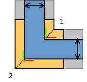
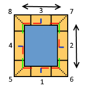
L corner (L) |
For L corner, you can specify the inner corner sub-assembly (1) and the exterior corner sub-assembly (2).
The corner sub-assembly is defined with the Corner sub-assembly wizard. With the wizard you can specify two sets of formwork items, which will be rotated according to the joining walls when the corner is placed in the model. The two corner sub-assemblies 1 and 2 are inserted according to the thickness of the joining walls. |
|
T corner (T) |
For T corner, you can specify two inner corners (1+2) and the back panel (3).
The corner sub-assembly is defined with the Formwork corner sub-assembly wizard. The back panel sub-assembly is defined with the Formwork sub-assembly wizard, and it contains a single insertion point + direction. When the T corner is placed in the model, the insertion point of the panel sub-assembly is located at the intersection of the joining wall center line and the exterior face of the horizontal wall. |
|
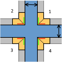
X corner (X) |
For X corner, you can specify the four inner corners (1-4).
|
|
Corner pilaster (CP) |
For corner pilaster, you can specify one inner corner sub-assembly (1) and three external corner sub-assemblies (2-4).
|
|
Pilaster (P) |
For pilaster, you can specify two inner corners (1 and 4), two external corners (2 and 3), and the back panel (5).
|
|
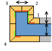
Pilaster inside corner (IP) |
For inner pilaster, you can specify one external corner (1) and three inner corners (2-3).
|
|
Bulkhead (B) |
For bulkhead, you can specify two external corners (1 and 2) and two middle panels (3 and 4). Panel 4 will be located at end of pour and all other sub-items will be offset by the given dimension.
|
|
Column (COL) |
For column, you can specify four panel assemblies and/or four corner assemblies.
|


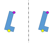
Create a corner sub-assembly
Corner sub-assembly is the building block for one side of the L corner or any of the inner corners in the T and X corners.
-
First model all the needed formwork objects. Only beams and/or custom parts can be used for modeling, so if you have other components, you need to explode them.
-
Decide which object should rotate with the first direction, and which objects should rotate with the second edge at the corner if/when the corner angle varies.
-
Start the Formwork corner sub-assembly wizard tool.
-
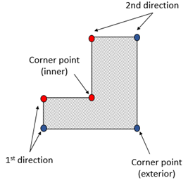
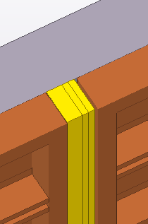
Pick the corner point as shown below.
-
Pick a point to identify the first direction.
-
Select the corner parts (custom parts and/or beams) at the first side of the corner.
-
Pick a point to identify the second direction.
-
Select the corner parts (custom parts and/or beams) at the second side of the corner.
-
Enter a name and click Finish to save the detailed half of the corner into an external file.
Note that the wizard should be run separately for the inner corner (red dots) and external corner (blue dots). Ensure that you do not include same objects twice as that would lead to duplicate objects in the model.
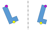
Create a panel sub-assembly
The panel sub-assembly is the building block of the formwork at the back side of the T corner and at pilasters.
-
First model all the needed formwork objects (custom parts and/or beams).
-
Start the Formwork sub-assembly wizard tool.
-
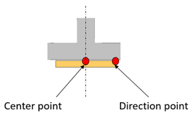
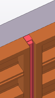
Pick the center point of the object at the back of the wall as shown below. This will be used as the insertion point when this panel sub-assembly is inserted in an actual T corner.
-
Pick a point to identify the direction.
-
Select the formwork parts (custom parts and/or beams) forming the panel sub-assembly.
-
Enter a name and click Finish to save the detailed panel and accessories into an external file.
Control the behavior of conditions with mirroring
When you define the corner sub-assemblies, it can be that the left-hand side corner needs to be placed in a right-hand side location. When this happens, the corner sub-assembly needs to be mirrored. Mirroring custom parts or formwork items is not always possible, especially when the part is not symmetric in any direction. The condition placing tool can use four different methods for mirroring. With the configuration file xxxxx.SubAssemblyItems.ini you can control which method will be used for a certain corner sub-assembly case. The file contains the mirroring method keyword, and after the keyword you can introduce the names of the items or partial name tags to identify multiple matching items.
| Mirroring method | Description |
|---|---|
|
Move
|
Default method. The custom part or formwork item is moved by an offset measured from the mirroring line to the center of the custom part or formwork item. |
|
RotateAroundZ
|
Input points are rotated 180 degrees around the center point at the mirroring line. |
|
RotateAroundAxis
|
Input points are first rotated 180 degrees around the mirroring line and then the custom part is rotated 180 degrees around the input axis. |
|
Mirror
|
Input point locations are mirrored and then the start and end points are swapped. |
|
FlipLocalXY |
Custom part or formwork item is moved and the local x and y axis at center are flipped (=rotated around local z 180 degrees). |
|
FlipLocalXZ |
Item or custom part is moved and local x and z axis at center are flipped (=rotated around local y 180 degrees). |
|
FlipLocalYX |
Item or custom part is moved and local y and z axis at center are flipped (=rotated around local x 180 degrees). |
|
TurnUpSideDown |
Item or custom part is moved and the mirroring is done by turning the component upside down in the global vertical direction. |

An example of the content in a configuration xxxxx.SubAssemblyItems.ini file.
// This file allows you to define how items and custom parts in corner sub assemblies
// are handled when placing the right handed corner into left handed situation or vice versa.
//
// By default items are just moved and no true mirroring happens. In following lines you can specify
// the mirroring methods used for certain items or custom parts. You can introduce full names or partial names.
//
// The possible methods are:
// #Mirror - input points are mirrored
// #RotateAroundAxis - input points are mirrored and the item/custom part is rotated 180 degrees around the axis:
// #RotateAroundZ - input points are rotated 180 degrees around the center point
// #FlipLocalXY - the item/custom part is moved and local X and Y axis's at center are flipped (=rotated around local Z 180 degrees)
// #FlipLocalXZ - the item/custom part is moved and local X and Z axis's at center are flipped (=rotated around local Y 180 degrees)
// #FlipLocalYZ - the item/custom part is moved and local Y and Z axis's at center are flipped (=rotated around local X 180 degrees)
// #TurnUpSideDown - the item/custom part is moved and "mirroring" is done by turning the component up-side.down
//
// Just list the names or partial names following the method keyword. Do not change the key words.
//
#Mirror
_FIXING_BOLT
#RotateAroundAxis
DOKA-3D-583002000
#RotateAroundZ
_INSIDE
_OUTSIDE
_CORNER
_LEFT
_RIGHT
#FlipLocalXY
#FlipLocalXZ
#FlipLocalYX
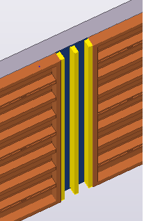
#TurnUpSideDownConfigure the fillers for the filler placing tool
xxxx.FormworkTools.Fillers.csv
With the filler placing tool you can create a filler by inserting timber beams or plywood and timber studs, and/or specific custom parts in the model. The creation of these model objects depends on the actual space to be filled. The basic principle of the creation of the various filler items is the following:
-
If the space to be filled is larger than the given minimum plywood width, the filler tool will create the plywood (=contour plate) and the timber studs.
-
If the space to be filled is smaller than the minimum plywood width, or plywood is not specified, the actual space is filled by one or more timber beams or custom parts. The target is to fill the actual space as completely as possible. The largest beams and/or custom parts are preferred and smaller pieces are created only when the space is smaller than the size of the larger pieces.
| Filler built with plywood and studs | Filler built with timber beams | Filler built with custom part |
|---|---|---|
|
|
|
|
To configure the filler tool, you can specify the properties for timber beam, plywood, and settings for one to ten alternatives of custom parts.
| Definition | Description |
|---|---|
|
Supplier |
Supplier name, which is typically the same for all rows. The name is shown in the Formwork supplier list. |
|
Family |
Family name, which is shown in the Product family list. |
|
Name |
Unique filler name. |
|
TimberWidths |
List of available timber beam widths (10 20 50 100). |
|
TimberDepth |
Depth of the timber beam. |
|
TimberAssPrefix |
Assembly prefix. |
|
TimberAssStartNo |
Assembly start number. |
|
TimberPartPrefix |
Part prefix. |
|
TimberPartStartNo |
Part start number. |
|
TimberName |
Name of the timber beam. |
|
TimberClass |
Class of the timber beam. |
|
TimberFinish |
Finish of the timber beam. |
|
TimberMaterial |
Material of the timber beam. |
|
StudWidth |
Width of the timber stud. |
|
StudDepth |
Depth of the timber stud. |
|
StudAssPrefix |
Assembly prefix. |
|
StudAssStartNo |
Assembly start number. |
|
StudPartPrefix |
Part prefix. |
|
StudPartStartNo |
Part start number. |
|
StudName |
Name of the timber stud. |
|
StudClass |
Class of the stud. |
|
StudFinish |
Finish of the stud. |
|
StudMaterial |
Material of the stud. |
|
PlywoodWidth |
Minimum width of the plywood. The actual width depends on the actual space to be filled. |
|
PlywoodThickness |
Thickness of the plywood. |
|
PlywoodAssPrefix |
Assembly prefix. |
|
PlywoodAssStartNo |
Assembly start number. |
|
PlywoodPartPrefix |
Part prefix. |
|
PlywoodPartStartNo |
Part start number. |
|
PlywoodName |
Name of the plywood part. |
|
PlywoodClass |
Class of the plywood part. |
|
PlywoodFinish |
Finish of the plywood part. |
|
PlywoodMaterial |
Material of the plywood part. |
|
Part1Name |
Name of the custom part 1. |
|
Part1Attributes |
Property file saved in the component dialog box to be used when the custom part is inserted in the model. |
|
Part1PlanePosition |
This is Position in plane when the custom part is inserted in the face view of the main formwork panel. |
|
Part1PlaneOffset |
This is Offset in plane when the custom part is inserted in the face view of the main formwork panel. |
|
Part1Rotation |
This is Rotation when the custom part is inserted in the face view of the main formwork panel. |
|
Part1RotationOffset |
This is Rotation offset when the custom part is inserted in the face view of the main formwork panel. |
|
Part1DepthPosition |
This is Position in depth when the custom part is inserted in the face view of the main formwork panel. |
|
Part1DepthOffset |
This is Offset in depth when the custom part is inserted in the face view of the main formwork panel. |
|
Part1StartOffset |
Offset of the first insertion point in relation to Input point 1. |
|
Part1EndOffset |
Offset of the first insertion point in relation to Input point 2. |
|
Part1Length |
Length of the custom part which is also the space to fill if/when this custom part is added to the model. |
|
Part1Height |
Height of the custom part. |
|
Part1LengthProperty |
Name of the length property of the custom part, if you are using a custom part whose length/width can be can be varying and/or parametric. The fields can be set also for Part2, Part3, and so on. You can configure multiple parts with separate additional rows. You need to keep the Supplier, Family, and Name the same as on the first row. |
|
Part1LengthMin |
Minimum length/width (the free gap to fill) the product can fill, if you are using a custom part whose length/width can be can be varying and/or parametric. The fields can be set also for Part2, Part3, and so on. You can configure multiple parts with separate additional rows. You need to keep the Supplier, Family, and Name the same as on the first row. |
|
Part1LengthMax |
Maximum length/width the product can fill, if you are using a custom part whose length/width can be can be varying and/or parametric. The fields can be set also for Part2, Part3, and so on. You can configure multiple parts with separate additional rows. You need to keep the Supplier, Family, and Name the same as on the first row. |
|
Part1HeightProperty |
Name of the height property of the custom part, if you are using a custom part whose length/width can be can be varying and/or parametric. The fields can be set also for Part2, Part3, and so on. You can configure multiple parts with separate additional rows. You need to keep the Supplier, Family, and Name the same as on the first row. |
|
Part2... Part3... Part10... |
In addition to the custom part 1, you can specify up to nine other custom parts. In practice, at least the PartXLength needs to be different for all specified custom parts. The tool selects the part with the most suitable length depending on the actual space to be filled. |