Example: Create a custom stiffener detail with variables
This example shows how to create a custom stiffener detail with variables that control the shape and position of the stiffeners.
Create a basic custom stiffener detail
This example shows how to create a basic stiffener detail.
-
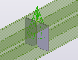
Create a beam with two stiffeners.
 Tip:
Tip:To create the stiffeners, you can use the Stiffeners (1003) component and then explode the component.
-
Click the
Applications & components
 button in the side
pane to open the Applications & components catalog.
button in the side
pane to open the Applications & components catalog.
-
Click the Access
advanced features
 button and select
Define custom component....
button and select
Define custom component....
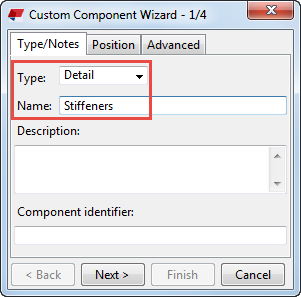
The Custom Component Wizard dialog box opens.
-
In the Name box, type Stiffeners.
-
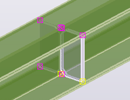
Select the stiffeners and the beam as the objects that form the custom component.
-
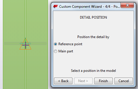
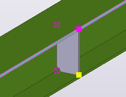
Select the middle point of the beam as the reference point.
Tip:
Switch to the plane view to select the middle point more easily.
-
Click Finish to finish creating the stiffener detail.
Tekla Structures displays a component symbol for the new custom component and adds the stiffener detail to the component catalog.
Create bindings to control the stiffener shape
This example shows how to bind custom component handles to a plane to control the shape of the stiffeners.
-
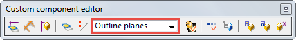
On the Custom component editor toolbar, select Outline planes from the list.
-
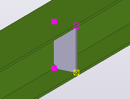
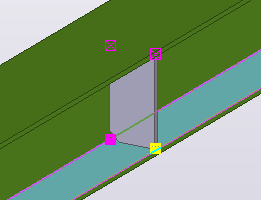
Bind the two inside handles of the stiffener to the beam web.
-
Select the two handles next to the beam web.
-
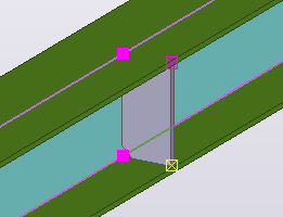
Move the pointer over the face of the web to highlight it.
-
Select the two handles next to the beam web.
-
Bind the two outside handles of the stiffener to the face of the top flange.
Use the same method as in step 5.
-
Bind the two bottom handles of the stiffener to the inside face of the bottom flange.
Use the same method as in step 5.
-
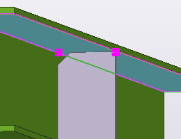
Bind the two top handles of the stiffener to the inside face of the top flange.
Use the same method as in step 5.
-
On the Custom component editor toolbar, click the Display variables button
 .
.
The Variables dialog box opens.
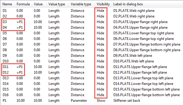
-
In the Formula box, enter =P1 for all variables that got values
during the binding of the handles.
For example:
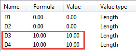
The variable P1 now controls the distances of these variables.
You have now created distance variables that control the stiffener shape.
Create bindings to control the stiffener position
This example shows how to bind custom component handles to a plane to control the position of the stiffeners.
-
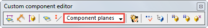
On the Custom component editor toolbar, select Component planes from the list.
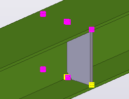
-
Select all the handles of both stiffeners.
-
Bind the handles to the vertical component plane.
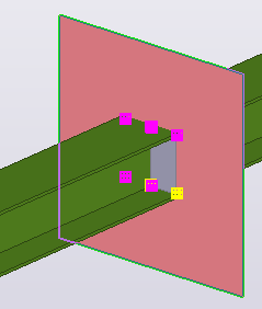
You have now created distance variables that control the position of the stiffeners.
Create variables to control the stiffener thickness
This example shows how to control the stiffener thickness so that it is one and a half times the web thickness rounded up to the nearest available plate thickness. The available thickness values are 10, 12, and 16 mm.
-
On the Custom component editor toolbar, click the Display variables button .
The Variables dialog box opens.
-
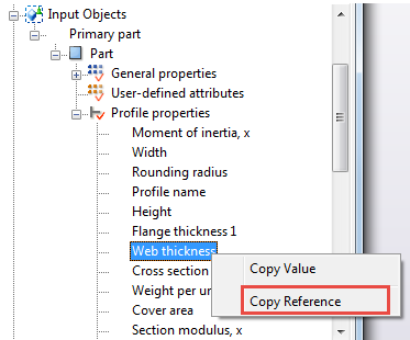
Right-click and select
Copy Reference.
-
Paste the reference value to
Formula after =1.5*.
 Note:
Note:A reference function refers to the property of an object, such as the web thickness of a part. If the object property changes, so does the reference function value.
-
In the Custom component browser, link the variable P3 to the
Profile property of the first contour plate.
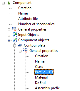
You have now created and linked all required variables that control the stiffener thickness according to the web thickness.
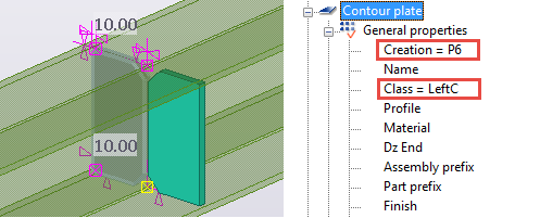
Create variables to control the creation of stiffener plates
This example shows how to create five variables to control which stiffener plates are created and what is the class of the plates.
-
On the Custom component editor toolbar, click the Display variables button .
The Variables dialog box opens.
-
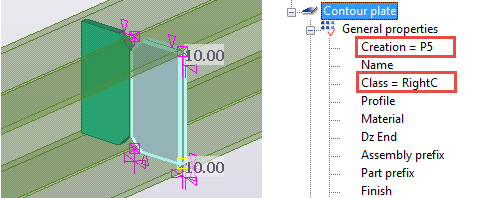
In the Custom component browser, link the variables P5 and
RightC to the right stiffener plate.
-
Link the variables
P6 and LeftC to the left
stiffener plate.