Offshore (9)
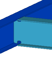
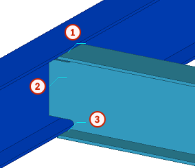
Offshore (9) connects a beam to another beam with welds. The component is designed to be used in offshore industry for creating notches and complex weld access holes, and to control the notch properties.
Objects created
-
Notches
-
Welds
Use for
|
Situation |
Description |
|---|---|
|
|
Connection between two beams. |
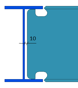
Profile limitations
You can create three different notch types:
- Free
- Heerema
- HSM
When creating a Free notch type, the main and the secondary beam do not always have to have the same size. You can set them up according to your needs and create the connection.
When creating Heerema and HSM notch types, the beam size depends on the selected Heerema and HSM settings.
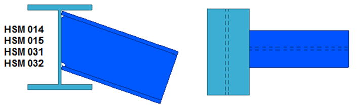
For all Free and Heerema types, and most HSM types, skewed secondary beams are allowed. Sloped secondary beams are only supported by some specific HSM types. See the table below for examples.
| Notch type | Example |
|---|---|
| Free |
|
| HSM |
|
Selection order
-
Select the main part (beam).
-
Select the secondary part (beam).
The connection is created automatically when the secondary part is selected.
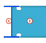
Part identification key
|
Part |
|
|---|---|
|
1 |
Beam |
|
2 |
Beam |
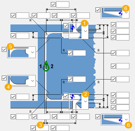
Picture 1 tab
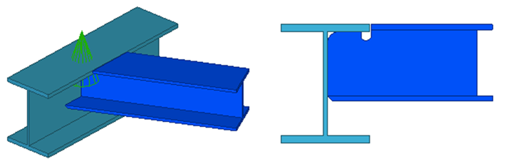
Use the Picture 1 tab to create notches in the direction of the web.
Notch type
Select the notch type and enter the notch values, if needed.
|
Option |
Description |
|---|---|
|
Free |
Enter the notch dimensions. |
|
Heerema |
When you select this option, the predefined Heerema options are listed below. The predefined values are entered automatically in the user-defined attributes of the secondary beam. |
|
HSM |
When you select this option, the predefined HSM options are listed below. The predefined values are entered automatically in the user-defined attributes of the secondary beam. |
|
No and clean up UDA |
No notch is created. The user-defined attributes have no values. |
Notches
|
Description |
|
|---|---|
|
1 |
Define the top flange notch for the secondary beam. |
|
2 |
Define the bottom flange notch for the secondary beam. |
|
3 |
Define a gap between the main beam web and the secondary beam end.
|
|
4 |
Define the bottom rounding and a possible weld access hole for the secondary beam. |
|
5 |
Define the top rounding and a possible weld access hole for the secondary beam. |
|
6 |
Create a cut that follows the sloped flange of the secondary beam. |
Fitting
Select the type of the fitting.
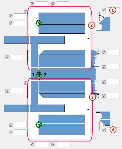
Picture 2 tab
Use the Picture 2 tab to create notches in the direction of the flange. The options on this tab can only be used if the notch type is set to Free on the Picture 1 tab. If you select a special type of notch (Heerema, HSM) on the Picture 1 tab, then the predefined values are entered automatically in the user-defined attributes.
Notches
|
Description |
|
|---|---|
|
|
Define the bevel angle for the top flange (optional). |
|
|
Define the top flange bevel. |
|
|
Define the bottom flange bevel. |
|
|
Define the bevel angle for the bottom flange (optional). |
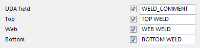
Weld description tab
Use the Weld description tab to control weld descriptions for the top, web and bottom welds.
|
Description |
|
|---|---|
|
|
Top weld |
|
|
Web weld |
|
|
Bottom weld |
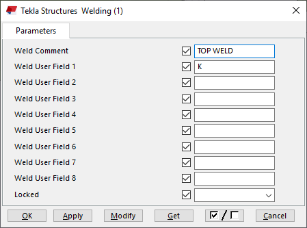
Use the boxes on the Weld description tab to define a name for the weld comment. Enter the text WELD_COMMENT in the UDA field. The descriptions in the Top, Web and Bottom boxes correspond to each weld.
Double-click a weld in the model and go to the user-defined attributes of the weld. The text is entered in the Weld Comment box.
General tab
Click the link below to find out more:
Analysis tab
Click the link below to find out more:
Welds
Click the link below to find out more: