Steel connections - enhanced IDEA StatiCa® link & new bracing connection type
The following enhancements were recently made for steel connections.
-
IDEA Statica link - the Checkbot application is now used for exporting connections to IDEA StatiCa. First introduced with release 2022 SP2.
-
Connections with Braces - a new connection type is added for where brace members are connected to beam/ column junctions. First introduced with release 2022 SP2.
- IDEA StatiCa Export - New Connection Noding setting - new “Connection noding" option added to improve connections created by default in IDEA Checkbot for some circumstances First introduced with release 2022 SP4.
IDEA Statica - link to Checkbot
Checkbot is the latest BIM application from IDEA StatiCa for managing the design of multiple connections linked from other applications such as Tekla Structural Designer. For more information about this see the Checkbot info page on IDEA StatiCa’s website. Some key points about this new feature are:
-
The new link has the following advantages:
-
Saves time by exporting multiple connections simultaneously thus reducing errors and speeding up connection design.
-
Connections can be designed for all or selected load cases/combinations by user choice.
-
You can access both Checkbot and Tekla Structural Designer simultaneously, for reviewing analysis results etc.
-
-
To use this updated link, it is necessary to install IDEA StatiCa version 22 onwards (together with this release).
-
Note that, for older versions of IDEA StatiCa (21.1.6.0541 and earlier) used with this or previous Tekla Structural Designer releases, connections will be exported using the old IOM Connection Runner link.
-
-
The Checkbot link is available for the following Regional Codes; US, Eurocode, Australia, and BS.
-
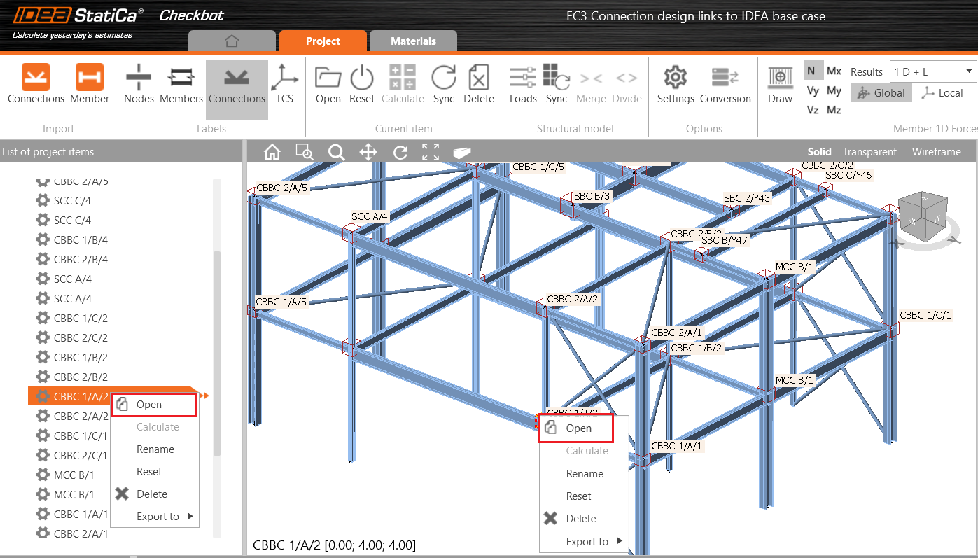
Connections can be exported to IDEA StatiCa from the connection window or from the scene view context menu as shown below.

-
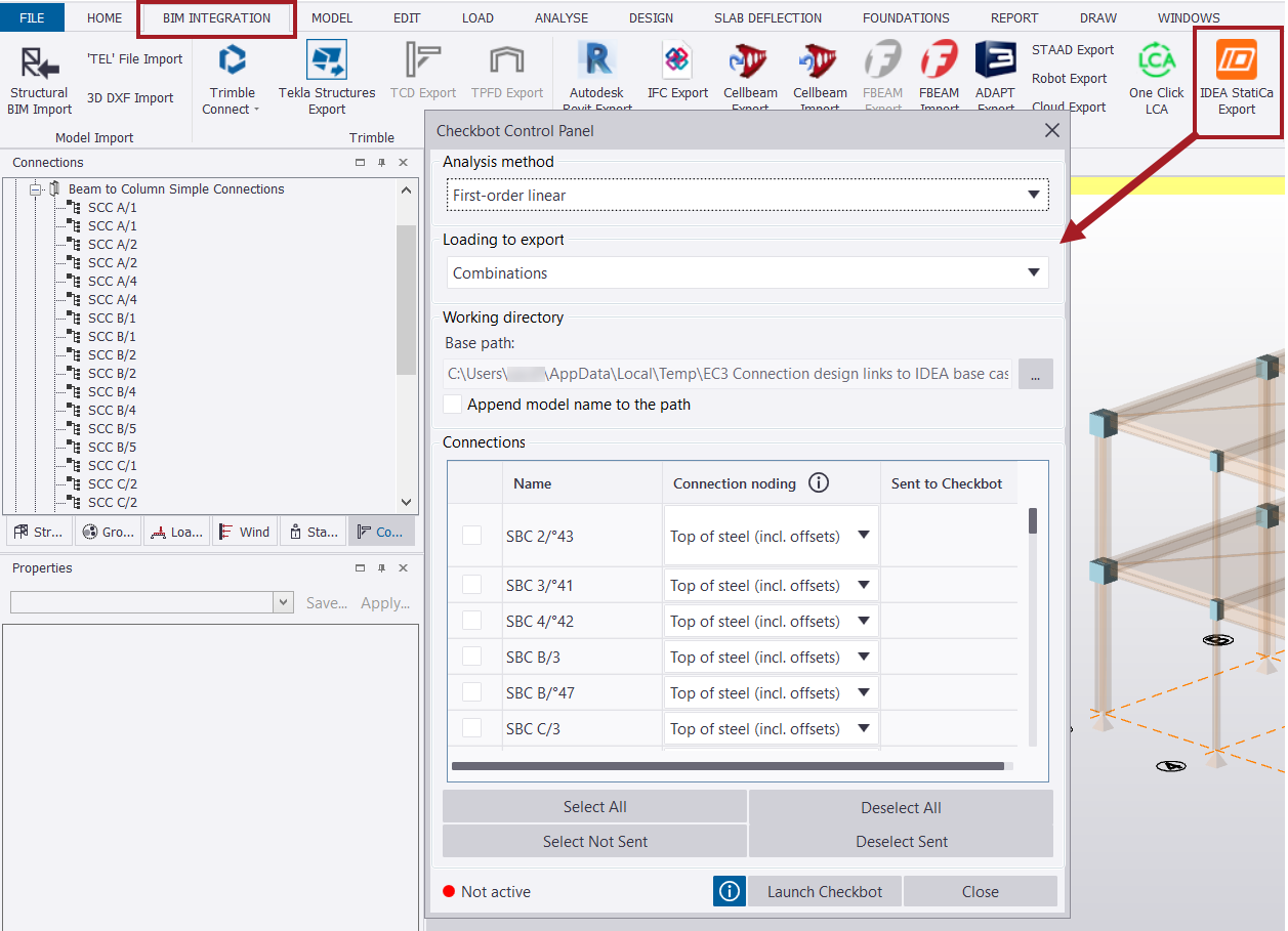
Connections can also be exported using the BIM INTEGRATION tab by selecting the new IDEA StatiCa Export button* as shown below.
*The IDEA StatiCa Export button only appears when the required version of IDEA StatiCa is installed.
-
For either export method, the new ‘Checkbot Control Panel’ dialog box is then displayed and populated with the list of connections available for transfer to IDEA StatiCa as shown below
-
-
The Checkbot Control Panel dialog box includes the following options:
-
Analysis method – a drop-down box lists the analysis types for selection.
-
Loading to export – This drop-down has two options: ‘Combinations’ and ‘Combinations & Loadcases’.
-
Working directory - this allows you to specify the path where the connection data will be stored. You can accept the default path or click the [...] button to browse to and select a different path.
-
Append model name to the path – this displays the full file path when checked and creates a folder with the Tekla Structural Designer model name in which exported connections are generated.
-
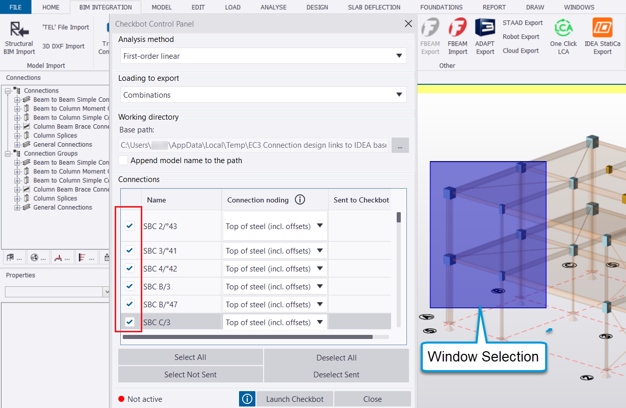
Select All – Selects all listed connections.
-
Select Not Sent – Selects connections that have not been exported to IDEA StatiCa previously.
-
Deselect All – Deselect all the selected connections in the list.
-
Deselect Sent – Deselects connections that have been exported to IDEA StatiCa previously.
-
Launch Checkbot – Opens Checkbot application page.
-
Information button 🛈 – Opens a dialog box of ‘IDEA StatiCa Checkbot instructions’ for guidance on the Checkbot
-
-
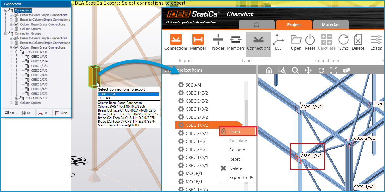
While the Checkbot Control Panel is open, selected connections are graphically displayed by coloured boxes - you can make further graphical selections of connections by any of the usual graphical methods such as a window selection, as shown below.
-
Connections that have previously been sent to Checkbot will be marked by means of a tick in the column ‘Sent to Checkbot’.
-
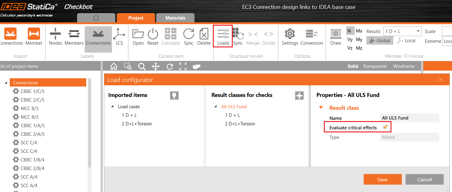
After launching the Checkbot the appropriate design code should be selected before selecting the option ‘Create project’.
-
Note that, by default, IDEA StatiCa considers critical effect combinations for connection design. You can untick the option ‘Evaluate critical effects’ to instead consider all load combinations.
-
-
In Checkbot, a connection can be selected from the list of project items or from the graphical view:
-
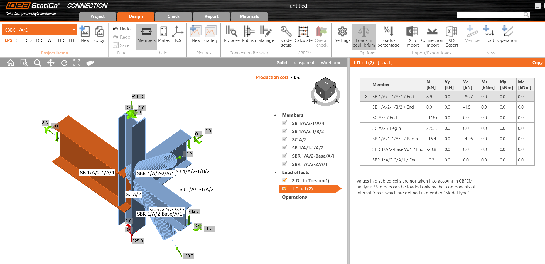
A selected connection can then be configured and designed in IDEA StatiCa CONNECTION for selected load cases/ combinations:
-
Current limitations:
-
The communication of data is one-way from Tekla Structural Designer to Checkbot. No data (such as section changes or connection details etc) are returned to the Tekla Structural Designer model, so the user is responsible for making any such changes manually.
-
The current link cannot handle a huge amount of connection data (e.g. thousands of connections with hundreds of load combinations) in a single instance. For such a case, it is necessary to select an individual or a group of connections to export.
- Where multiple connections are formed at a joint in Tekla Structural Designer - such as a moment connection (MCC) and a simple connection (SCC) - these must be exported separately.
-
New bracing connection type
Complementing the new IDEA StatiCa export, a new automatically configured bracing type is added in this release for beam/ column junctions to which one or more brace members also connect. The new type is termed ‘Column Beam Brace Connections’, abbreviated as CBBC. The CBBC connection type can be exported to IDEA StatiCa only - it is not designed within Tekla Structural Designer nor exported to Tekla Connection Designer.
-
Key aspects of this new connection type are:
-
When Update Connections is run, CBBC connection objects are automatically created at locations where one or more brace members are connected at a beam-column junction.
-
The CBBC connection type has a separate graphical connection box in the scene and associated control for visibility in Scene Content settings.
-
All CBBC connections are listed in the connections window and are grouped by the brace section sizes.
-
As for other connections, the name and reference format of CBBC’s can be controlled via Model Settings > Texts/Formats
-
A tooltip provides detail about the CBBC connection when the cursor is over the connection box, as shown in the picture above.
-
CBBC connections can be exported to IDEA StatiCa for design just as described above for existing connection types.
-
IDEA StatiCa Export - new Connection noding setting
A new setting “Connection noding" is added to connection properties to improve the
connections created by default in IDEA StatiCa for some circumstances. The setting is an
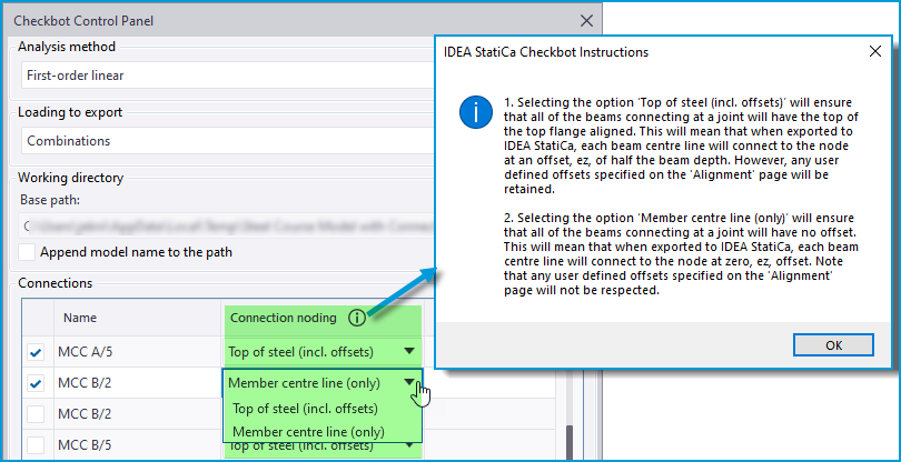
attribute of each connection and is accessed either in the Checkbot Control Panel via the
new “Connection noding” headed column, or in the Properties Window for selected connections,
as shown in the picture below.
-
Click the information button 🛈 in the Checkbot Control Panel to see a comprehensive explanation of the two options for this setting “Top of steel (incl. offsets)” and “Member center line (only)”.

-
Key aspects of the new setting options are as follows:
-
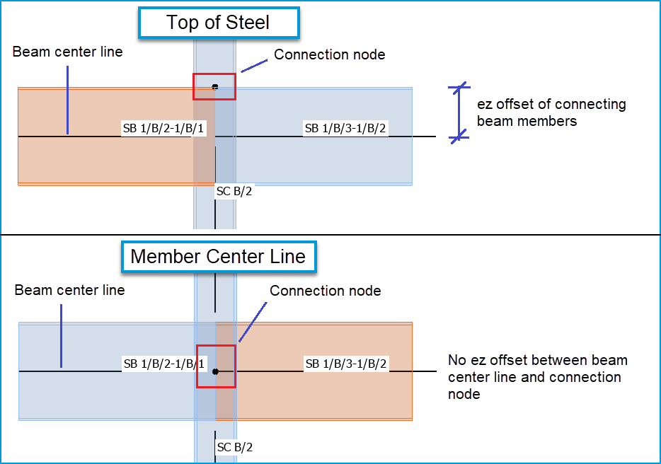
Top of steel (incl. offsets) - this option retains the previous workflow of exporting connections to IDEA StatiCa. It is the default option since we expect it will continue to be the preferred option most of the time.
-
As previously, this option will generally ensure that in IDEA StatiCa all of the beams connecting at the joint have the top of their top flanges aligned (providing there are no offsets), with the connection joint at this level.
-
Each beam center line will have an offset from the connection node, ez, of half the beam depth, as illustrated in the picture below.
-
Thus, In the less common case of connecting beam members carrying axial load, generally small eccentric moments can develop due to this offset which are reported as ‘Unbalanced forces’ in IDEA StatiCa. If a connection designer does not wish to have these forces, they can try the alternative option described below.
-
-
Any user-defined offsets specified in the ‘Alignment’ settings of members are retained.
-
-
Member center line (only) - this option ignores physical member offsets in the Tekla Structural Designer model.
-
When exported to IDEA StatiCa, each beam center line will connect directly to the connection node with no eccentricity, regardless of any user-defined offsets specified in the ‘Alignment’ settings of members.
-
Since there is no offset, this option eliminates the possibility of eccentricity moments from connecting member axial load. However the resulting IDEA StatiCa connection may not replicate the required physical connectivity at the joint.
-
-