Release notes: Tekla Structural Designer 2022 SP4
This service pack will update your Tekla Structural Designer installation to version number 22.4.0.116 and should be installed to ensure optimum function of the program. It includes a number of new features, enhancements and issue resolutions as detailed below.
If you are upgrading from a version earlier than the immediately prior release 2022 SP3 (version 22.3.1.0 released Oct 2022), you can find details of requirements, enhancements and fixes for all previous releases in Tekla User Assistance (TUA) and Tekla Downloads via the links below:
Licensing & Installation
Licensing:
-
No new license is required for this version.
-
Client License Service Version - if it is not already, the latest Tekla Structural License Service should be installed with this release on clients.
-
Note that when installing this on a client, only the Client License Manager option needs to be installed.
-
Installation:
- This service pack requires Tekla Structural Designer 2022 first release (version 22.0.0.49) or later to be installed and will update your current version.
- Integration
- Tekla Structures - if you wish to integrate with Tekla Structures you
should install both this release and Tekla Structures 2022 (the latest
SP*) for optimum performance.
-
Note that there have been significant improvements to integration - especially for rebar - in the 2021 release of Tekla Structures. For more information about this please see the Tekla Structures Help Topic Tekla Structural Designer Import and Export.
- *Note that there is currently a recently found issue running the direct link (which produces a .tsmd file when both Tekla Structures and Tekla Structural Designer are both installed) between Tekla Structures 2022 SP6 and Tekla Structural Designer. This is scheduled to be fixed in Tekla Structures 2022 SP7. Until this is available you are advised to use Tekla Structures 2022 up to SP5, or to use the option to create a .CXL file from Tekla Structures, which functions correctly in SP6.
-
-
Tekla Tedds - to use Design using Tekla Tedds with this release, you must install Tekla Tedds 2022 AND you should ensure you have installed the latest Service Pack for this version and the latest 2022 Engineering Library Update. These can be obtained from Tekla Downloads.
-
Autodesk Revit© - the Tekla Structural Designer Integrator for Autodesk Revit© 2023 was released in December 2022. For more information about this see the Tekla Structural Designer Integrator for Autodesk Revit 2023© Release Notes. The installation for this is available in Tekla Downloads. If you are now using Autodesk Revit© 2023, you can install this to perform BIM integration with Tekla Structural Designer.
-
The other currently supported Revit© versions are: 2020 (Integrator version 6.03), 2021 (Integrator version 7.02) and 2022 (Integrator version 8.0). For more information about these see the Tekla Structural Designer Integrator June 2021 updates page. If you are performing BIM integration with any of these previous Revit© versions, we recommend you install the latest version of the associated Integrator.
-
- Tekla Structures - if you wish to integrate with Tekla Structures you
should install both this release and Tekla Structures 2022 (the latest
SP*) for optimum performance.
-
Previous Versions and file compatibility - files from all previous versions can be opened in this release, however note that, once saved, they cannot then be opened in a previous release. If you wish to retain this option we therefore recommend using the File > Save As… option to save a copy of the file in the previous release and retain the original.
Issues with associated bulletins
-
[TSD-12866] - Slab Design - Slab Patches - incorrect design moment for Maximum result strip option
This issue relates to all regional codes. Each slab patch uses result strips to determine the reinforcement area requirements. For each strip you are required to specify if the design force should be determined from the “Maximum” or the “Average” force. The design force is correctly determined provided that “Average” is selected, but can be incorrect when “Maximum” is selected. For more information please see Product Bulletin PBTSD-2301-1.
-
This issue is fixed in this release.
-
General & Modeling
-
A number of additional fixes which are not detailed explicitly here are also made to improve general performance and stability. An example of such an issue is given directly below.
-
[TSD-6547] - Member Design Summary Report - reduced RAM usage when producing
The compilation process for the Member Design Summary Report has been refined to reduce RAM usage. As a result, the time it takes to generate member design summary reports has been improved generally - and in some examples (larger models with many design combinations) dramatically so.
-
-
[TSD-12438] - Locate Solver Elements and Nodes from the Solver Model Data tables
You can now double-click on a row in the ANALYZE > Model & Results > “Nodes” and “Elements” tables to locate the associated node/ element in the Solver model. When a node/ element row is double-clicked, the Solver view automatically pans and zooms to the node/ element location and it is both selected and indicated with a clear arrow.
Interoperability
-
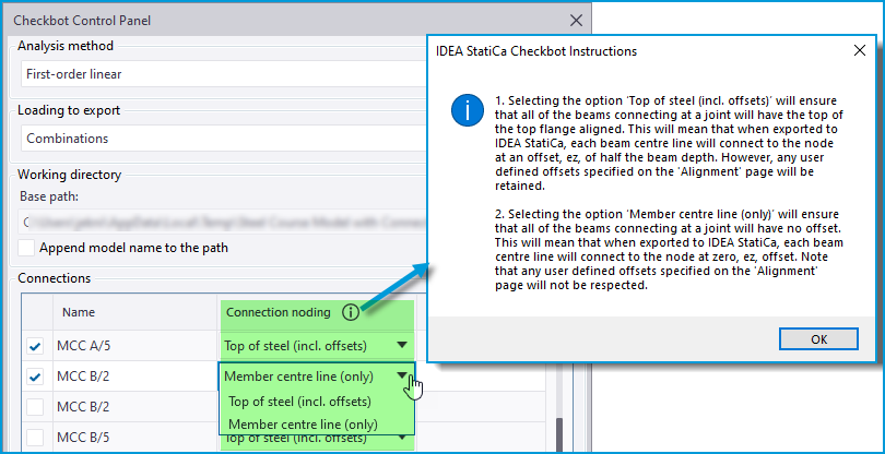
[TSD-11294] - Connections - IDEA StatiCa Export - New Connection Noding setting
A new setting “Connection noding" is added to connection properties in this release to improve the connections created by default in IDEA StatiCa for some circumstances. The setting is an attribute of each connection and is accessed either in the Checkbot Control Panel via the new “Connection noding” headed column, or in the Properties Window for selected connections, as shown in the picture below.-
Click the information button 🛈 in the Checkbot Control Panel to see a comprehensive explanation of the two options for this setting “Top of steel (incl. offsets)” and “Member center line (only)”.
-

-
Key aspects of the new setting options are as follows:
-
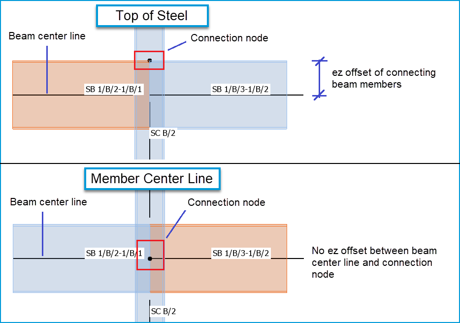
Top of steel (incl. offsets) - this option retains the previous workflow of exporting connections to IDEA StatiCa. It is the default option since we expect it will continue to be the preferred option most of the time.
-
As previously, this option will generally ensure that in IDEA StatiCa all of the beams connecting at the joint have the top of their top flanges aligned (providing there are no offsets), with the connection joint at this level.
-
Each beam center line will have an offset from the connection node, ez, of half the beam depth, as illustrated in the picture below.
-
Thus, In the less common case of connecting beam members carrying axial load, generally small eccentric moments can develop due to this offset which are reported as ‘Unbalanced forces’ in IDEA StatiCa. If a connection designer does not wish to have these forces, they can try the alternative option described below.
-
-
Any user-defined offsets specified in the ‘Alignment’ settings of members are retained.
-
-
Member center line (only) - this option ignores physical member offsets in the Tekla Structural Designer model.
-
When exported to IDEA StatiCa, each beam center line will connect directly to the connection node with no eccentricity, regardless of any user-defined offsets specified in the ‘Alignment’ settings of members.
-
Since there is no offset, this option eliminates the possibility of eccentricity moments from connecting member axial load. However the resulting IDEA StatiCa connection may not replicate the required physical connectivity at the joint.
-
-
-
Remoting API Enhancements
There have been some enhancements to the Open API with this release - for information about these see the Tekla Structural Designer 2022 Open API Release Notes page.
-
[TSD-12807] - Trimble Connect Link - now uses Trimble Connect Model API
The Trimble Connect BIM API is due to be end-of-lifed. With this update, the Trimble Connect link now uses the Trimble Connect Model API. This ensures there should be no break in service for the link.
-
[TSD-12807] - Trimble Connect Link - now uses Trimble Connect Model API
With this update, the Trimble Connect link now uses the new Trimble Connect Model API. This ensures there should be no break in service for the link.-
The link previously used the Trimble Connect BIM API, which is due to be end-of-lifed soon - for more details about this see this post in the Trimble Connect User Forum on the Trimble Community website (note to view this post you must 1) have a Trimble ID Account 2) Sign in to Trimble Community with this and 3) Join the community).
-
Loading
-
[TSD-12898] - Area load on wind panel over concrete wall applied in wrong direction
For an area load applied in the Global Z direction to a wind panel which then spanned on to a meshed concrete wall, the sign of the decomposed load would be incorrect. Process warnings and errors were issued in the Loading tree making this issue apparent. This issue is corrected in this release.
Validation
-
[TSD-12584] - Validation Tooltips - Improved hints and new action/advice text
It has always been possible to see more information about Validation issues in the cursor tooltip by moving the cursor over a specific validation Error/ Warning message in the Validation tree of the Status Window. In this release a large number of these validation issue tooltips have been enhanced with improved explanation/ hints text and a new Action/ Advice section has been added giving suggested steps to take to address the issue. An example is shown in the picture below. This puts more information at the engineers fingertips so that they can identify and address model issues themselves efficiently without recourse to other resources/ support.

Analysis and Results
-
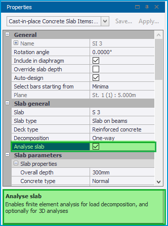
[TSD-12139] - Slabs - FE Meshing enabled for One-way slabs
Slabs set to the “One-way” decomposition method can now be optionally set to be analyzed. Though the slabs remain “One-way” from a setting perspective, when the new “Analyze Slab” property is enabled they are essentially treated in the same manner as “Two-way” slabs with orthotropic properties enabled and fit in with all the established procedures for Two-way slabs. For more about orthotropic slabs see the Help Topic Orthotropic slabs (and slab specific stiffness adjustments).-
The properties of a one-way slab now have a checkbox option “Analyze slab”. When enabled, the slab is meshed with 2D elements and analyzed in all the appropriate analyses; load decomposition and FE Chasedown always, and 3D Building analysis when the slab level/ plane is set to be meshed in 3D analysis.
-
Though its function remains the same, the level/ plane setting “Mesh 2-way Slabs in 3D Analysis” is accordingly renamed to “Mesh Slabs in 3D Analysis” and the Tool tip and property information descriptions for this setting are modified to include “1-way slabs set to be analyzed…”.
-
-
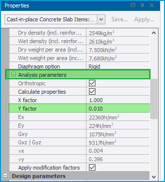
When “Analyze Slab” is enabled, the slab “Analysis Parameters” are activated with similar defaults to those for orthotropic two-way slabs, other than the “Y factor” which defaults to a value of 0.010, as shown in the picture below.
-
Meshed one-way slabs are analyzed in exactly the same manner as two-way orthotropic slabs, and all the tabular data results available for 2-way meshed slabs - and their associated report items - are also populated for one-way meshed slabs.
-
It should be noted that the analytical behavior of "one-way" slabs set to be analyzed will not be perfectly idealized one-way (including for load decomposition). Such slabs will generally behave in predominantly one-way manner. For more about this point, see "One-way" spanning orthotropic slab example.
-
-
[TSD-10805] - New Reporting of Section and Material Properties used in analysis
In solver model views, when any analysis element (1D or 2D) is selected its properties are displayed in the Property Window. The data displayed is enhanced in this release to list the section and material properties which were finally used in the analysis after the application of all Modification Factors (for more on these see Use of modification factors), as shown in the picture below (new data highlighted).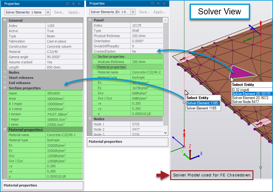
-
Note the following:
-
This feature does not change the analysis models or procedures used in any way - it simply adds a new method of reviewing the element analysis properties.
-
To view these new analysis properties details, it is necessary to select a Solver model for a specific analysis type from the context menu options in the Solver view - e.g. “Solver model used for 1st Order Linear” or “Solver model used for FE Chasedown”*...etc.
-
*For Chasedown solver models it is necessary to open a Solver view of a specific Chasedown Sub model via the Sub Models group of the Structure Tree, then select the Chasedown solver model to view in this (the new properties detail is not displayed in a general 3D view)
-
-
The values displayed are the ones used the last time an analysis of the selected type was run.
-
They include the effects of modification factors from analysis settings.
-
If you change modification factors it is necessary to re-run the analysis in order to see the changed effects both in terms of analysis results and in the properties reported in this solver model view.
-
-
-
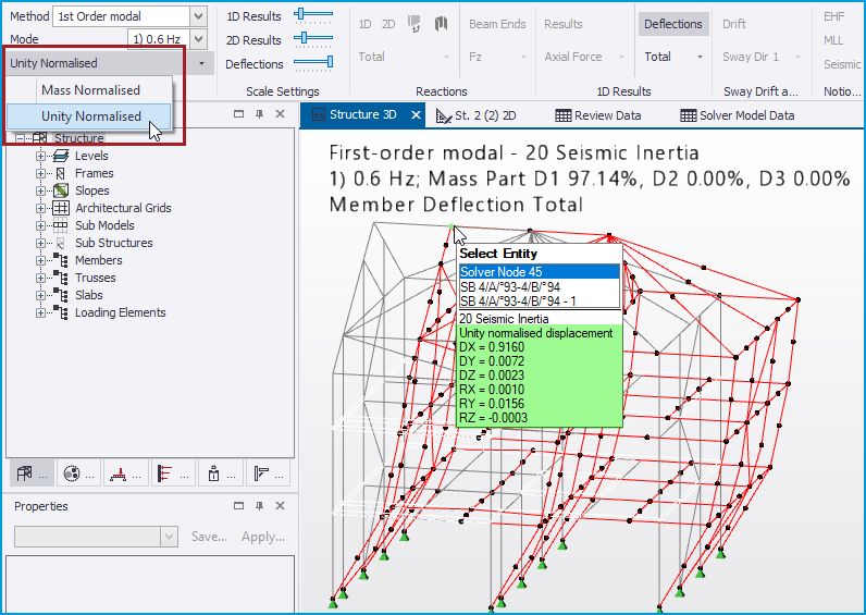
[TSD-12301] - Modal Analysis - New Unity Normalized Mode Shape Reporting
In prior releases, modal analysis mode shapes were always reported using the Mass normalized convention. Following customer requests, a new option is added in this release to report the Unity normalized alternative. This may be desirable for example where modal results are to be post processed in some way following guidance which is written with the expectation of unity normalized mode shapes. For more about mode shape displacement values and normalization methods, see the TUA Article What is the magnitude of the deflections from Modal Analysis?
-
This enhancement introduces a new option to select between Mass and Unity normalized results which is added in the following views:
-
The Results View ribbon when viewing mode shapes graphically.
-
The Model & Results view ribbon when viewing the “Mode Shape by Node” Modal results table.
-
The Wind Tunnel Data results view ribbon for the “Mode Shape by Level” results table.
-
Note that the option selected in any one of these views is also set in the others.
-
-

-
Note the following:
-
The selected mode shape reporting option is saved with the model.
-
In the graphical view the only visible difference is in the tooltip information as the cursor is moved over nodes (there is no change to the mode shape).
-
In the tabular view the table heading clearly states the currently selected reporting option.
-
The selected reporting option is observed when mode shape data is exported to Excel, or to a report, and stated in the exported/ reported data heading information.
-
When viewing Unity normalized results, it should not be expected that a displacement of 1.0 in DX, DY or DZ will necessarily exist at a point of maximum modal displacement, nor that sorting the table by X, Y, or Z values will necessarily expose the maximum nodal resultant value. This is because it is the maximum resultant displacement that is scaled to unity and mode shapes may involve displacement of all nodes in more than one direction.
-
-
-
[TSD-12905] - Foundation Reactions Result Table - negative values exported to Excel as Text
When the recently added ANALYZE > Model & Results > Foundation Reactions result table was exported to Excel, negative reaction values would be incorrectly set to the Excel Text category. This is fixed in this release - negative values are now correctly set to the Excel Number category.
-
[TSD-12307] - Wall Releases not applied for Mat Slabs
In previous releases for the circumstances of mat slabs with soil bearing springs supported by meshed walls, the wall (major axis) releases (pinned and continuous (incoming members pinned)) did not work correctly - the slab mesh was still analytically fixed to the wall mesh which could produce undesirable wall and slab moments. In addition, the soil spring supports were applied to the nodes along the top of the meshed wall. This issue is fixed in this release with the intended analytical releases now being applied correctly and no soil spring supports applied to the wall nodes.
Design
General
-
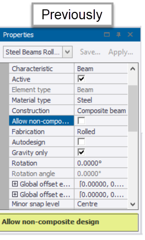
[TSD-5914] - Composite Beam - New Try non-composite setting
Following customer feedback, a new setting now enables composite beams to be checked as non-composite both when auto design is enabled and when it is not, and whether the composite solution passes or fails. This applies to the British Standards (BS), Eurocode and United States (ACI/AISC) Regional Codes.
-
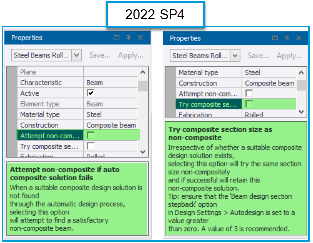
As shown in the picture below, the previous option “Allow non-composite design” has been renamed to “Attempt non-composite if auto composite solution fails” and a new option “Try composite section size as non-composite” is added. Both options also include detailed descriptions of their operation in the Properties Window, in both the cursor tooltip and information box when selected as shown in the picture below.
-
For existing models with he previously named setting “Allow non-composite design” enabled, the “Attempt non-composite if auto composite solution fails” will be enabled and behavior will be unchanged when “Try composite section size as non-composite” is disabled.
-
-
The general operation of these settings is as follows:
-
Attempt non-composite if auto composite solution fails - essentially the same as the previous “Allow non-composite design”: when enabled, if a suitable composite design solution is not found by auto-design, it will attempt to find a satisfactory non-composite solution.
-
When design is complete, irrespective of whether the solution is non-composite, the Construction property of the beam remains as “Composite beam” when only this setting is enabled.
-
-
Try composite section size as non-composite - when enabled, irrespective of whether a suitable composite design solution exists, the design process will try the section size non-compositely (i.e. without studs) and if successful will retain this non-composite solution.
-
When design is complete and a non-composite solution is successful, the Construction property of the beam will change to “Non-composite beam”, making it clear which beams are no longer composite.
-
Note that the “Beam section design stepback” option mentioned in the settings description currently applies only to the USA Regional code.
-
-
-
-
-
[TSD-12361] - New check for Incompatible Design Section Order
New validation is added to check for a Design section order which is not compatible with the current Regional design code (which can occur when a model’s Regional design code is changed). In addition, the Design section order is now displayed in member properties even when the Autodesign setting is disabled. An incompatible Design section order now causes the design of any member to end with a warning status and note displayed in the check results.
-
[TSD-12081] - Piled Mat - improved pile punching check effective depth calculation
Additional refinement has been added to the pile punching checks for piled mats for the circumstance of the tension reinforcement being that in the top of the slab, by explicitly calculating the effective depth as the distance between the top of the pile and the average position of the top reinforcement.
Regional Code British Standards
-
[TSD-12015] - Concrete Beam Design - improved autodesign for shear links
In some circumstances in previous releases the design process could fail where the design shear was lower than the minimum design threshold (0.5*Vc). In this release the design process is improved to ensure that the reinforcement provided by auto-design is always at least the nominal amount resulting from the user settings and the minimum applicable code requirements, and this issue no longer occurs.
-
[TSD-12705] - Steel Joist Design - improved determination of Maximum Design UDL
Determination of the maximum design UDL for KCS joists has been improved in this release to be generally less conservative.
Notes
The number in brackets before an item denotes an internal reference number. This can be quoted to your local Support Department should further information on an item be required.