Create bearing walls
Bearing walls provide resistance to vertical compressive loads (but not lateral loads) and support certain other member types. Unreinforced masonry walls, for example, can be modeled as bearing walls.
You can model bearing walls over several story heights. In these cases, Tekla Structural Designer creates a single wall with a uniform thickness between the base and top level.
Tekla Structural Designer determines the location of the wall from the alignment specified in the bearing wall properties, and the selected insertion points.
Note: Bearing walls do not perform the same
function as wall panels. In other words, bearing walls do not allow you to apply
loads calculated by the Wind Wizard to your structure.
Therefore, in order to apply wind loads, you must create additional wall panels in the same locations as the bearing walls.
Material type
Three Material types are available for bearing walls:
-
Concrete
-
Timber
-
General
Concrete Bearing Walls
There are two Concrete types available:
-
Normal
-
Lightweight
The Grade lists all the available grades in the Materials database under the current head code for the selected Concrete type.
Timber Bearing Walls
The Grade lists all the available grades in the Materials database under the current head code for Timber.
General Bearing Walls
The Grade lists all the
available General materials in the Materials database under the current head
code.
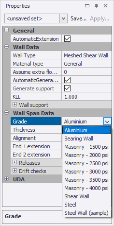
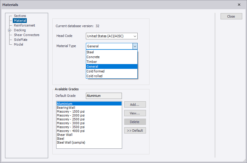
If the grade you want to use is not
listed, you can open the Materials
dialog and add the grade to the database, taking care to first select the
General material type as shown below.
Geometric rules
- Bearing walls can only be created as rectangular in a vertical plane.
- Wall openings are ignored.
- Bearing walls cannot be included in cores.
Create bearing walls in a level view
Note: Ensure that you have defined the
construction levels between which the wall will run, and the grid points between
which the wall will lie.
-
On the
Model tab, click
 Bearing Wall.
The wall will adopt the properties displayed in the Properties window.
Create bearing walls in a frame or structure view
Note: In order to define a wall in a frame or
structure view, you must have already defined the construction levels between
which the wall will run and the grid points between which it will lie.
-
On the
Model tab, click
Bearing Wall.
The wall will adopt the properties displayed in the Properties window.