Slab meshing controls
Meshing issues tend to be caused when the area being meshed ends up with really narrow strips of slab, for example when the slab edge ends up just outside the edge of a column.
On the Meshing page of Analysis Settings certain meshing tolerance controls can be adjusted when required to solve these type of issue.

The model shown above has various challenging situations which are discussed below along with an indication of whether changing the automatic merging distances in Analysis Settings can have an impact:
1. Column face close to parallel slab edge - (yes)
In this example the slab edge is positioned 50mm outside the column face. The view above left shows the analysis model you would get when the Column boundary to slab edge merging distance is < 50mm. The view above right shows the model you get if the merging distance is set to 50mm or above. The column corner nodes merge (move to) the slab edge eliminating the narrow strip.
The simplified analysis model avoids mesh quality warnings and gives almost identical results in terms of column transfer forces and slab design.
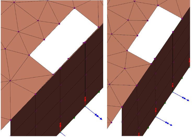
2. Column face close to inclined slab edge - (yes)
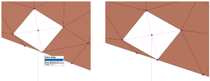
In this example the slab edge sits just a few mm outside the column corner. The view above left shows analysis model where a very poor quality element runs past the corner, (you would only end up with this model if the Column boundary to slab edge merging distance were to be set less than the default 5mm. The view above right shows the model you get if the merging distance is set to the default 5mm or above. One column corner node merges (moves to) the slab edge eliminating the narrowest part of strip.
The simplified analysis model avoids mesh quality warnings and gives almost identical results in terms of column transfer forces and slab design.
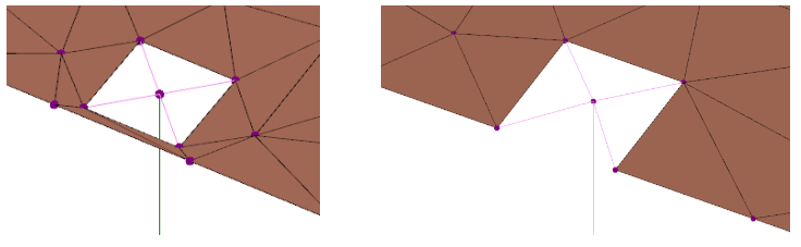
3. Column close to multiple non-parallel slab edges - (yes)

This is just another variation on positions 1 and 2. The view above left shows analysis model you would end up with if the Column boundary to slab edge merging distance were to be set less than the default 5mm. The view above right shows the model you get provided the default merging distance (5mm) is retained - meshing is simplified avoiding mesh quality warnings and gives almost identical results in terms of column transfer forces and slab design.
4. Opening near slab edge - (yes)
In the following examples merging will make things better, but the reality is that a slab will never be cast with thin isolated strips at the edge - you cannot effectively reinforce a 50 to 100mm wide strip of slab. In all these the ideal solution is that the modelling should reflect the reality of realistic minimum edge distances.
A hole is defined approximately 20mm from the slab edge. The effect is the same as at the column cut-out boundary - above on the right shows how with the Opening to slab edge merge distance set to 50mm the opening corners move to the slab edge. This creates a better analysis model.
5. Opening near wall inserted along slab edge - (yes)
This is basically the same as the previous situation except that a wall happens to be defined along the edge. In such cases the user is often tempted to extend the opening into the physical width of the wall but does not extend it right to the wall insertion line.
There are pros and cons to both models. On the left the narrow meshed strip of slab can give mesh quality warnings and errors. On the right the slab mesh is better, but the model relies a bit more heavily on the wall beam to transfer moments. However, the overall minor axis moment transferred to the wall only drops from 75.7 to 72.5 kNm.
6. Circular opening near slab edge - (yes)
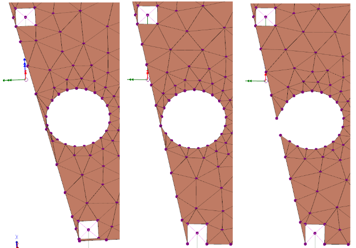
Above left shows the sort of meshing that will occur when a circular opening is created near to the slab edge. Above centre shows an example where closest point on the circle is merged to edge. The meshing looks a bit better but this is still not a great model because you will get strange local results at the connecting node. On the right where theOpening to slab edge merge distance is set to 100mm the edge gets completely broken - this is probably the best model.
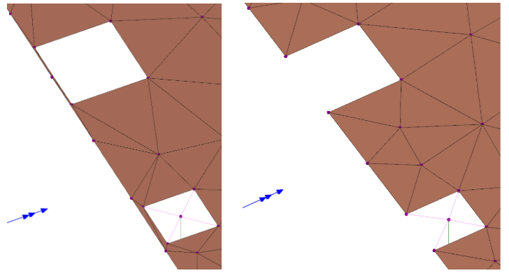
7. Closely spaced openings - (no)
These are all examples where the merging settings have no effect.
In each case the problems can generally be resolved by adjusting the openings so that they overlap slightly.

Above - shows meshing when a narrow (unbuildable?) strip of slab is left between openings.
Below shows the model when the openings are manually adjusted to eliminate this strip.
8 and 9. Opening near column - (no)
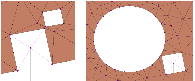
In both these cases it would again be better to adjust the openings so that they overlap the column boundaries as suggested below.

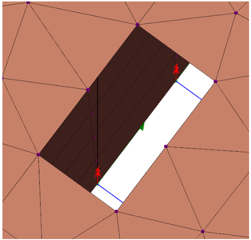
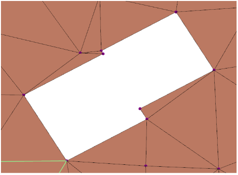
10. Opening near wall with slab on other side - (no, unless certain conditions apply)
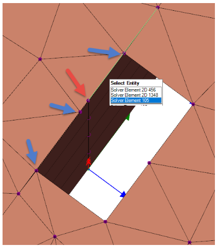
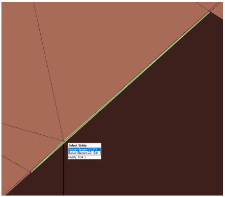
In this case the opening is defined with an edge that is approximately 4mm from the insertion line of the wall. With the Hardpoint to edge distance tolerance at the default of 5mm this creates a model that is poorly connected along the edge of the opening. The node highlighted in red is not included in the slab meshing (because it is just 4mm away from the edge). The 3 slab nodes highlighted in blue are not directly connected to the wall.
If the hard point distance is reduced to 1mm then the model changes as shown below, the node marked in red above is now included in the slab mesh so the adjacent nodes have a better connection to the wall.
However, the best model would be obtained if the opening edge got exactly aligned with the wall, this can actually be quite hard to achieve in the manual positioning of openings. A workaround at present is to force a “slab mesh boundary” along the line of the wall by making the slab on one side slightly different to the slab on the other - then the automatic mergings will create a model as shown below.