Print to a .pdf file, plot file (.plt) or printer
2019
Tekla Structures
Print to a .pdf file, plot file (.plt) or printer
You can print drawings and selected drawing areas to .pdf files, plot files (.plt) to be sent to a plotter/printer, or to a printer. You can also change the colors and the related line thicknesses (pen numbers) in the printed drawings.
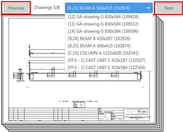
- To show a preview of a drawing, select it from the list of drawings at the top of the Print Drawings dialog box, and click Click here to load a preview.
The drawings are shown one by one in a preview. The preview shows the drawings always up to date. Use Next and Previous to scroll through the set of selected drawings.
- Define the printing settings on the Options tab. The available settings depend on the printing option that you have selected:
Option Description File location
Enter the location for the .pdf or plot file, or use Browse... to browse for the folder.
The \Plotfiles folder under the model folder is the default value.
Include revision mark to file name
Add the mark of the latest revision of the printed drawing to the file name.
Revision number is used by default. If you always want to use the revision mark, set the advanced option XS_SHOW_REVISION_MARK_ON_DRAWING_LIST to TRUE.
Open folder when finished
Open the .pdf or plot file folder in Windows Explorer after the printout has been created. Open folder when finished
Open the .pdf file after it has been created. Output to single file
Print the selected drawings to a single .pdf file. If you do not select this option, each drawing will be printed in a .pdf file of its own.
File name
Give a file name to a pdf file. The file name is compulsory if you are printing to a single file.
File extension
Specify a file name extension for the plot file. The default is plt. File prefix
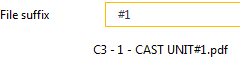
File suffix
Enter a specific prefix and/or suffix in the file name.
When you enter a prefix or suffix, the print file name preview under the File prefix and File suffix boxes will reflect the change immediately.
The print file name can also be controlled by a couple of advanced option switches for customizing print file names. These switches do not work for single combined multiple drawings .pdf file.
Fit to paper
Fit the drawing to a specific paper size.
Scale
Force the printout to a specific scale.
The Scale value will turn red if the drawing cannot fit on the specified sheet.
Center drawing on paper Center the drawing on the sheet (or sheets). Print on multiple sheets
Print on multiple sheets and specify the direction of printing the sheets. Select either Left to right, top to bottom or Bottom to top, right to left. When you use Print on multiple sheets , select a particular paper size.
Paper size
Define the paper size or use automatic size. With the Auto setting Tekla Structures selects the paper size that has the least wasted area when the scaled print is fitted to the printable area on the sheet.
Printers are often unable to print on the full area of a sheet, and leave borders. The printable area is determined for the selected printer when the option Printer or Plot file is selected. For .pdf files, the printer is not known so the output is sized to the full sheet. However, when printing a .pdf , the same problem exists and the drawing content is fitted to the printable area of whatever printer is being used. The printable area is shown with white background and the non-printable border is shaded gray in the image below.
Orientation
Define the orientation or use automatic orientation.
The Auto setting means that the orientation that wastes least space is selected automatically.
Color
Select if the output is to be Color , Black and white or Grayscale.
Number of copies
Define the number of plot file or paper copies to be printed.
Collate
Collate the printout when you are printing multiple copies.
Embed fonts
Embed the fonts in a .pdf file.
This ensures that fonts may be reproduced in a system that does not have the same fonts installed, but this also increases the file size. In certain cases, fonts may be embedded automatically. When using non-Latin fonts, it is recommended that embedding is selected, otherwise the .pdf may not be displayed correctly.
Select area
Select a rectangular area from an open drawing to only show and print that area. This option only works when you have a drawing open.
All settings in the dialog box also work when this option is selected, and you can change the orientation, line thicknesses, and paper size, for example.
Show entire drawing
When you have selected an area with Select area , the Show entire drawing button is displayed, and you can use it to show the entire drawing in the preview again.
- Go to the Line properties tab to map colors to line thicknesses (pen numbers) and set the printout colors:
Option Description Object color
Shows the basic set of object colors.
Color on output
Set the printout color by clicking a color box under Color on output and selecting a new color from the displayed colors. You can also define custom colors.

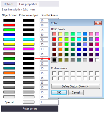
Different output color is often used when you just need one or two lines in color and the rest in black. Output colors are used in all printing options (printer, plot file and PDF file). The output colors are saved to and loaded from the printing settings files.
If you select the Printer line colors through , and change a line color, the change is immediately shown in the drawing.
The Color on output only applies when the Color option is set to Color on the Options tab in the Print Drawings dialog box.
For instructions on how to show correct line thicknesses in the Black and white mode, see Line thickness in drawings.
Line thickness
Enter the line thickness for each color in the boxes.
Line thicknesses are expressed as a multiple of the advanced option XS_BASE_LINE_WIDTH value. The default value for this advanced option is 0.01 mm. For example, pen number 25 will give a line weight of 0.25 mm.
In color drawings, the lines are shown with different thicknesses on the screen and in the printouts if the Printer line widths switch is active in .
You can define Invisible color for parts and shapes in drawings in the part or shape properties. The Invisible color is not shown in printouts, neither on paper nor on .pdf.
For instructions on how to show correct line thicknesses in the drawing in the Black and white mode, see Line thickness in drawings.
Reset colors
You can reset the printout colors:
To reset an individual output color, click the corresponding Object color color box. The Color on output color box will change to have the same color.

To reset all output colors to be the same as the object colors, click the Reset colors button.
Example : Printing to multiple sheets
In the example below the setting Bottom to top, right to left is selected. The numbers indicate the printing order of the sheets.
In the next example, the option Left to right, top to bottom is selected.