Edit Reinforcement dialog
2020
Tekla Structural Designer
Edit Reinforcement dialog
Summary
The Edit Reinforcement dialog box allows you to modify the reinforcement used in a punching shear check. The graphic in the dialog box previews the reinforcement and updates to match the changes that you make. The graphic also indicates other items that are specific to the check location.
Location
To display the dialog:
- Right click on an existing punching check item.
- In the context menu, select Edit Reinforcement.
Content
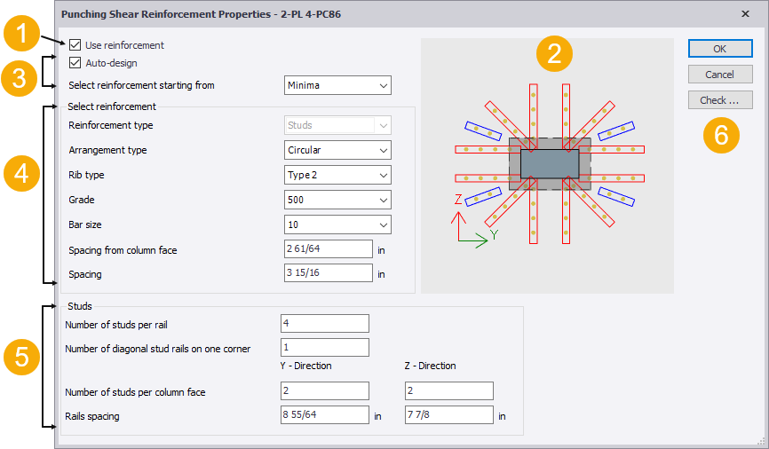
1. Use reinforcement
Selecting the Use reinforcement option allows you to apply a default punching reinforcement arrangement that can either be checked or used as the starting reinforcement for an auto design.
2. Preview graphic
The components of the preview graphic are as follows:
Stud rail reinforcement
Stud rail reinforcement is only shown if you have selected the Use reinforcement option.
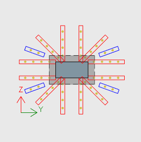
The red design rails signify rails considered in design.
The blue detailing rails are only considered for detailing purposes.
Perimeters
Perimeters are displayed as dashed lines around the column section and will have different shapes and positioning depending upon the head code being worked to.
Control Perimeter (EC)
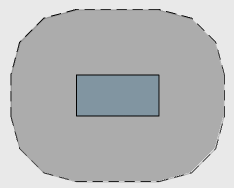
The control perimeter is the perimeter of the dark grey area as shown above. This will vary depending on existing slab edges and openings.
Critical Perimeter (ACI)
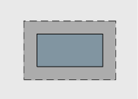
The critical perimeter is the perimeter of the dark grey area as shown above. This will vary depending on existing slab edges and openings.
Slab opening dead zones
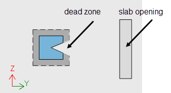
Slab opening dead zones are displayed as interruptions in perimeters and reinforcement.
Punching shear check local axis

Using the YZ system orients the X axis upwards following the right-hand rule. This is also the local axis system for the column elements, so it is easier to relate.
Additional Perimeters
If reinforcement is found to be required, additional perimeters will be displayed representing positions beyond the critical/control perimeter where the reinforcement requirement is checked.
3. Auto-design
If you select the Auto-design option, the reinforcement is increased until either a pass is achieved or the limiting reinforcement parameter limits have been exceeded. You can then select the starting point in the Select reinforcement starting from list.
The Select reinforcement starting from list allows you to select the staring point for auto-design procedures. The options are:
- Minima: removes the current arrangement and starts the reinforcement with the minimum allowed bar size.
- Current: auto design starts from the current bar arrangement. The Current option is only available if you have selected Use reinforcement in the Properties window.
4. Select reinforcement parameters
Reinforcement type
In the current release, only stud reinforcement is available.
Arrangement type
Allows you to define whether the reinforcement arrangement is orthogonal or circular.
Rib type
Allows you to specify the reinforcement rib type.
Grade
The reinforcement grades that are available here are set in the Materials dialog box.
Bar size
The reinforcement bar sizes that are available here are in the Materials dialog box.
Spacing from column face
Defines the spacing of the first bar in each rail from the column face.
Note: The option is only available if the Use reinforcement option has been selected.
Spacing
Defines the spacing between bars along each rail.
Note: The option is only available if the Use reinforcement option has been selected.
5. Studs parameters
Number of studs per rail
Allows you to define the number of studs on each rail.
Number of diagonal stud rails on one corner
Allows you to define the number of stud rails adjacent to each corner of the column.
Note: The option is only displayed when Arrangement type is set to Circular.
Number of studs per column face
Allows you to define the number of stud rails adjacent to the column face in the local y and z directions.
Rails spacing
Allows you to define the spacing between rails in the local y and z directions.
6. Buttons
| Button | Description |
|---|---|
| OK |
Saves the current reinforcement and closes the dialog box. |
| Cancel |
Closes the dialog box without saving changes. |
| Check... |
Opens the Results dialog box that displays the detailed results for the current design. |