Flat slab design workflow
2020
Tekla Structural Designer
Flat slab design workflow
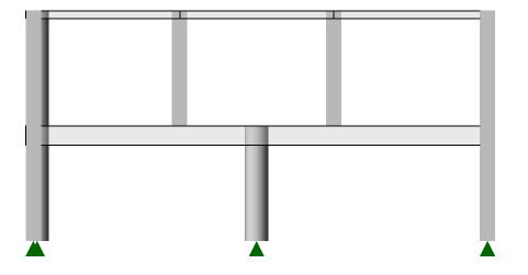
A simple flat slab model as shown below is used in order to demonstrate the techniques involved in the slab design process.
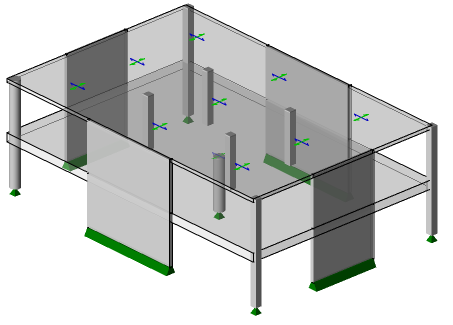
Note that there is a transfer level at the first floor:
Set up pattern loading
If necessary you should consider manually splitting and joining slab panels to facilitate management of the pattern loading process.
By default, only beam loads, and slab loads that have been decomposed on to beams, are patterned. Loads applied to slabs should be manually patterned using engineering judgement; this is achieved on a per panel basis for each pattern load by toggling the loading status via Update Load Patterns on the Load ribbon.
Establish slab design moments
Analysis is required to establish the moments to be used in the slab design - this analysis is automatically performed when either Analyze All, Design Concrete or Design All are run.
Typically these moments are taken from the FE chasedown model results - as each floor is analyzed individually this method mimics the traditional design approach.
If you have elected to mesh 2-way slabs in the analysis, the 3D Analysis model results will also be considered.
Note:
It is NOT suggested that it should be standard practice to mesh 2-way slabs, for slabs that are not needed to participate in the lateral load analysis it is better not to mesh in 3D, however: - you may choose to mesh them to cater for the possibility of un-braced flat slab design. - more likely, you may do so to deal with significant transfer slabs - e.g. a shear wall supported by a slab, (there is no need to create a system of fictitious beams).
Consider simple (linear) deflection (US customary units)
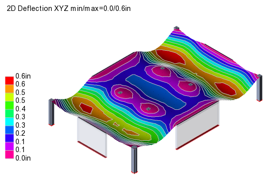
Approximate slab deflections can be obtained by reviewing the 2D deflection contours for the FE Chasedown results in the Results View, (typically by opening a separate Level view of each floor).
Note:
Deflection results for combinations should be viewed based on "service" rather than "strength" factors - in this way the applied stiffness adjustments do not need to account for load factors.
Note:
For Flat Slab panels - Deflection checks are not performed automatically. In practice flat slab models are often irregular, so some degree of engineering judgement will be required.
If the Head Code you are working to prevents you from running a Rigorous Deflection Check you can still use a "Deemed-to-Satisfy" method to assess deflections utilizing slab strips as outlined below:
-
With the level view displayed in 2D, click Create Strip and create a strip between supports.
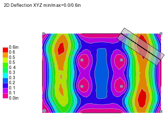
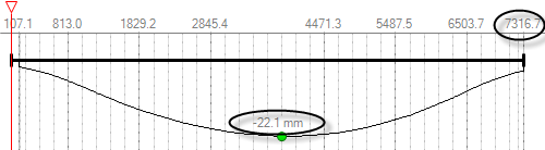
- To display the strip results right-click the strip and choose Open Load Analysis View. The maximum deflection and span of the strip are both reported.
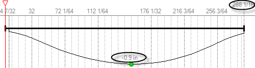
In this example there is a requirement to limit total deflection to span/240
Taking the span as the length of the slab strip: 288in
Deflection limit: 288/240 = 1.2 in
Actual deflection: 0.9 in - the check passes
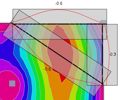
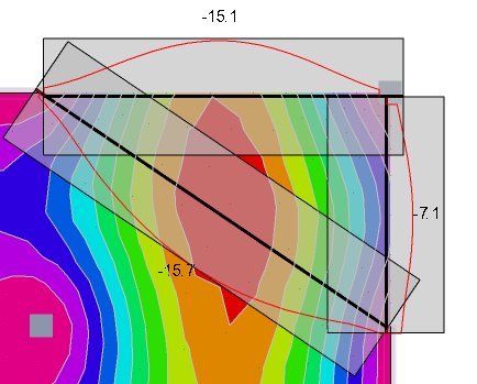
The initial check was performed taking the diagonal across a slab panel. Checks should also be made between the horizontal and vertical spans. More generally, check the max deflection occurring along a straight line between any two support points.
Consider simple (linear) deflection (metric units)
Approximate slab deflections can be obtained by reviewing the 2D deflection contours for the FE Chasedown results in the Results View, (typically by opening a separate Level view of each floor).
Note:
Deflection results for combinations should be viewed based on "service" rather than "strength" factors - in this way the applied stiffness adjustments do not need to account for load factors.

Note:
For Flat Slab panels - Deflection checks are not performed automatically. In practice flat slab models are often irregular, so some degree of engineering judgement will be required.
If the Head Code you are working to prevents you from running a Rigorous Deflection Check you can still use a "Deemed-to-Satisfy" method to assess deflections utilizing slab strips as outlined below:
- With the level view displayed in 2D, click Create Strip and create a strip between supports.
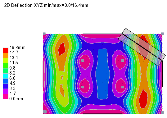
- To display the strip results right-click the strip and choose Open Load Analysis View. The maximum deflection and span of the strip are both reported.
In this example there is a requirement to limit total deflection to span/250
Taking the span as the length of the slab strip: 7317mm
Deflection limit: 7317/250 = 29mm
Actual deflection: 22mm - the check passes
The initial check was performed taking the diagonal across a slab panel. Checks should also be made between the horizontal and vertical spans. More generally, check the max deflection occurring along a straight line between any two support points.
Select a Level, or sub-model
In models with distinct floor levels you should use 2D Views to work on the floor design one level at a time. Occasionally the "3D geometry" of a model may make it less easy to distinguish between individual floors, in which case it may be easier to design the floors one sub-model at a time.
Note:
When working in a 2D View use the right-click menu to design or check slabs and patches: this saves time as only the slabs and patches in the current level are considered. Running Design Slabs or Design Patches from the Design ribbon will take longer as it considers all the slabs and patches in the model.
Add patches
This is an interactive process - requiring a certain amount of engineering judgement.
Typically you should expect to work on this one floor at a time, (making use of multiple views when creating patches as discussed below).
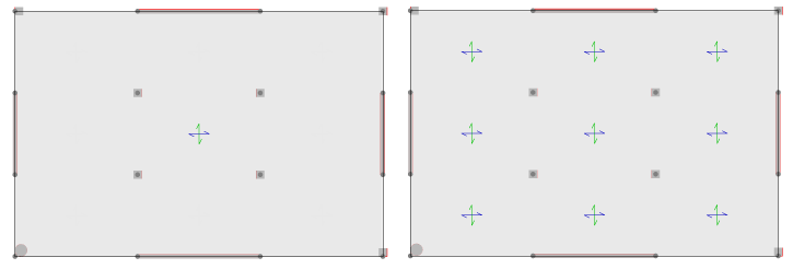
It is suggested that you add patches in the Results View while looking at relevant moment contours - For example you might (after selecting the FE chasedown result type) have Mx moments on in one view on the left and My moments in a second view on the right, as below:
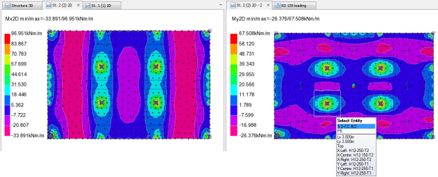
By doing this, it is possible to see how patches extend over the peaks.
Typically, at the initial patch creation stage you should make the patches a reasonable size and not be concerned if they are a bit too big - as this should be reviewed/resolved at the patch design optimization stage.
In a "slab on beam" situation, you may want to add beam and wall patches to cover the full extent of non-zero top bending moments. By doing so you can then set the top reinforcement in the slab panels to none and the panel design should still pass.
Design panels
Note: Panel design is dependent on the areas of patches (patch areas which are excluded from panel design) - hence patches should be added before panels are designed.
To design multiple slab panels, either:
- From the Design ribbon run Design Slabs in order to design or check all the panels in the model - by default newly created panels will all be in "auto-design" mode - so reinforcement is selected automatically.
or
- In the 2D View of the floor which you want to design right-click and choose either Design Slabs or Check Slabs. Working in this way restricts the design or checking to the slab panels in the current view. This will be a much faster option on large buildings and avoids time being wasted designing slab panels at levels where patches have not yet been set up.
Note: When accessed from the right-click menu, these commands operate as follows:
- Design Slabs will re-design slabs (potentially picking new reinforcement) regardless of the current autodesign setting.
- Check Slabs will check the current reinforcement in slabs regardless of the current autodesign setting.
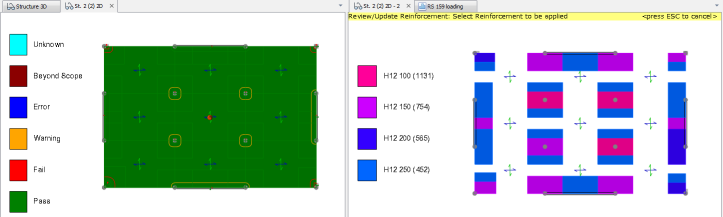
Review/optimize panel design
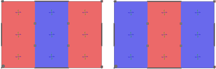
Once again it is suggested that you use split Review Views to examine the results as indicated below.
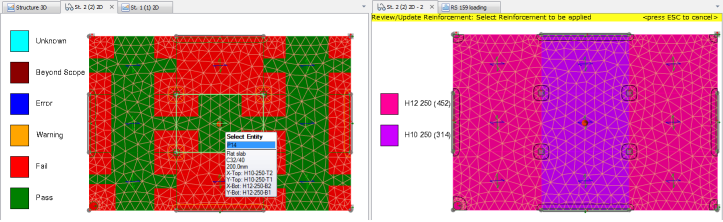
In this example a number of members are not heavily loaded so you could consider resizing or designing them interactively.
The view on the left shows Slab Design Status, the view on the right shows Slab Reinforcement in the panels. Note that the tool tip indicates all panel/patch reinforcement as you hover over any panel.
If the selections are unacceptable you may need to review the design settings. e.g - if 8mm dia bars are selected and you would just never use anything less than a 10mm bar in a flat slab, then set that as a minimum.
Once the selections are reasonable it is advisable to select all the panels and swap them out of auto-design mode (and after this point be careful not to use the right-click option to design panels unless you really want to).
Note:
Auto-design will select the smallest allowable bars at the minimum centers necessary to provide sufficient reinforcement area. Larger bars are only tried when the minimum permissible spacing is reached. Design options allow you to control the minimum acceptable bar sizes and spacings. It is important to use these settings so that the reinforcement established in the slabs is sufficiently spaced to allow introduction of additional reinforcement in the patches. For example you might set a "minimum spacing (slab auto design)" = 150mm.
After using the Review View update mode to standardize reinforcement you can then run Check Slabs from the right-click menu to check the revised reinforcement.
Remember:
- Consider swapping between Status and Ratio views - if utilizations all < 1 but some panels failing then problems are to do with limit checks. The Ratio view is better for helping you focus on the critical panels.
- During this process it will also make sense to be adding panel patches in which the reinforcement is set to none and strip is set to average. The purpose of this is to smooth out local peaks at the most critical locations which would otherwise dictate the background reinforcement level needed to get a pass status.
Design patches
Having established and rationalized the slab panel reinforcement which sets the background levels of reinforcement, it is now logical to design the patches which will top up the reinforcement as necessary within the strips of each patch.
To do this, either:
- From the Design ribbon run Design Patches in order to design or check all the patches in the model - by default newly created patches will all be in "auto-design" mode - so reinforcement is selected automatically.
or
- In the 2D View of the floor which you want to design right-click and choose either Design Patches or Check Patches. Working in this way restricts the design or checking to the patches in the current view.
Note: When accessed from the right-click menu, these commands operate as follows:
- Design Patches will re-design the patches (potentially picking new reinforcement) regardless of the current autodesign setting.
- Check Patches will check the current reinforcement in the patches regardless of the current autodesign setting.
Review/optimize patch design
At this stage the patch sizes can be reviewed:
- Beam patches - can the width be adjusted (minimized)
- Wall patches - can the width be adjusted (minimized)
- Column patches - Is the size reasonable - this relates to code guidance about averaging in columns strips - it is not reasonable to average over too wide a width. If in doubt safe thing to do is err on the side of caution and make them a bit smaller.
- Having got the sizes sorted out and the patches re-designed, swap them out of auto-design mode.
- Now click Slab Reinforcement in the Review View to review and standardize the patch reinforcement. For instance in column patches this might include forcing the spacing of the slab reinforcement to be matched (if the slab has H12-200, then in the patch don't add H12-125, swap to H16-200 - then there will be alternate bars at 100 crs in this strip of the patch.
Add and run punching checks
Punching checks require slab reinforcement to be defined/known in order to determine punching capacities.
Punching checks can be added over the entire floor, or structure by windowing it. You can then select any check and review the properties assigned to it. Internal/edge/corner locations are automatically determined (with a user override if you require). Once added click Design Punching Shear and the checks are done and status is shown as:
- Pass - if no shear reinforcement is needed
- Warning - if shear reinforcement is needed
- Fail - if it is impossible to achieve required capacity by adding share reinforcement
- Unknown - if check not run yet
- Beyond scope or error - if for example the centroid of the column/wall lies outside the slab
Note:
In order to see the punching check status in the Review View you might need to first switch off Slab Items and Slab Patches in Scene Content.
Rigorous deflection check
In Tekla Structural Designer you can choose to adopt a rigorous approach to slab deflection calculation using iterative cracked section analysis. For futher details, see: Calculate slab deflections
Create drawings and quantity estimations
Drawings that convey the structural intent are easy to create. It should be borne in mind that these are NOT the final detail drawings, their purpose is to eliminate the need for manual mark-up drawings as a means of communication between the engineer and the detailer
Print calculations
Create a model report that includes the panel, patch, and punching check calculations that have been performed. (The default Building Design report includes these along with design calculations for other member types in the model).