Opening Frame
Opening Frame creates an open frame for wall, roof, or floor openings. The frame is created between beams or columns.
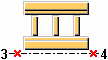
Objects created
-
Top frame
-
Bottom frame
-
Vertical posts
-
Additional component (optional)
Use for
|
Situation |
Description |
|---|---|
|
|
Open frame between two columns with top frame, bottom frame, and two pairs of vertical posts. |
|
|
Open frame between two skew columns with top frame, bottom frame, and two pairs of vertical posts. |


Before you start
Create two columns or beams.
Selection order
-
Select the main part.
-
Select the secondary part.
-
Pick the start point of the opening frame.
-
Pick the end point of the opening frame.
Part identification key

|
Part |
|
|---|---|
|
1 |
Top frame |
|
2 |
Vertical post |
|
3 |
Bottom frame |
Picture tab
Use the Picture tab to control the frame position, offsets, and spacings.
Frame distance

|
Description |
Default |
|
|---|---|---|
|
1 |
Distance between the top and the bottom frames. |
1200 mm |
Frame horizontal offset

|
Description |
Default |
|
|---|---|---|
|
1 |
Horizontal offset of the frame from the start/end point. |
0 mm |
Frame vertical offset

|
Description |
Default |
|
|---|---|---|
|
1 |
Vertical offset of the frame from the start/end point. |
0 mm |
Frame position
|
Option |
Description |
|---|---|
|
|
Default Top AutoDefaults can change this option. |
|
|
Top |
|
|
Bottom |
|
|
Middle |


Frame mirroring
Mirror the frame in relation to the start point and the end point.
When the frame is mirrored, also part rotation and additional connections follow the mirroring.
|
Option |
Description |
|---|---|
|
|
Default Frame is not mirrored. AutoDefaults can change this option. |
|
|
Frame is not mirrored. |
|
|
Frame is mirrored. |


Created parts
|
Option |
Description |
Default |
|---|---|---|
|
Frames to create |
Define whether top, bottom, or both frames are created. |
Both |
|
Pairs vertical posts |
Define how many pairs of vertical posts are created. |
3 |
|
Spacing pairs (S1, S2, Sn) |
Spacing between the pairs. The spacing is measured from the first vertical post inner side of the first pair to the first vertical post inner side of the second pair.
|
1800 mm |
|
Spacing vertical posts (W1, W2, Wn) |
Spacing between the vertical posts in the pairs. The spacing is measured from the first vertical post inner side to the second vertical post inner side. If the number of spacings is greater than the number of the entered spacing values, the missing spacing values are the same as the last spacing value. |
500 mm |
|
Create welds |
Define whether welds are created. The options are:
|
Posts-Frames(5) |
Parts tab
Use the Parts tab to define the part properties.
Dimensions
|
Option |
Description |
Default |
|---|---|---|
|
Top Frame |
Top frame profile by selecting it from the profile catalog. |
L100*50*5 |
|
Bottom Frame |
Bottom frame profile by selecting it from the profile catalog. |
L100*50*5 |
|
Vertical Posts |
Vertical post profiles by selecting them from the profile catalog. |
L100*50*5 |
|
Option |
Description |
Default |
|---|---|---|
|
Pos_No |
Prefix and start number for the part position number. Some components have a second row of fields where you can enter the assembly position number. |
The default part start number is defined in the Components settings in . |
|
Material |
Material grade. |
The default material is defined in the Part material box in the Components settings in . |
|
Name |
Name that is shown in drawings and reports. |
|
|
Class |
Part class number. |
Twin profiles
|
Option |
Description |
Default |
|---|---|---|
|
Twin profiles |
|
No |
Type
Define the profile rotation for single profiles or for twin profiles.
Options for single profile:
|
Option |
Description |
|---|---|
|
|
Type 1 |
|
|
Type 2 |
|
|
Type 3 |
|
|
Type 4 |
|
|
Type 5 |
|
|
Type 6 |
|
|
Type 7 |
|
|
Type 8 |
Options for twin profile:
|
Option |
Description |
|---|---|
|
|
Type 1 |
|
|
Type 2 |
|
|
Type 3 |
|
|
Type 4 |
Clearance
|
Option |
Description |
Default |
|---|---|---|
|
Clearance |
Clearance between the twin profiles. You can define the clearance only if the Twin Profile field is set to Yes. |
0 mm |
Position
|
Option |
Description |
Default |
|---|---|---|
|
On plane |
Part position on work plane. |
Middle |
|
Rotation |
Define how much the part is rotated around its axis on the work plane. You can define the rotation only for twin profiles. Define the rotation for single profiles in the Type field. |
Front |
|
At depth |
Part position, in terms of depth, perpendicular to the work plane. |
Middle |
Connections tab
Use the Connections tab to define the properties of connection components that are created between the parts.
Connection properties
Note:
With twin profiles the connection is created between only one part of the twin profile, and thus the connection is not well supported. If you use connections to connect twin profiles, a warning message is displayed.
|
Option |
Description |
Default |
|---|---|---|
|
Connection number |
Define a connection that connects the parts by selecting it from the component catalog. If the field is empty or set to 0, welds are created instead. |
|
|
Attribute file |
Select an attribute file for the connection. |
standard |
Welds tab
Click the link below to find out more: