Cranked beam (41)
Cranked beam (41) connects two beam ends. The beam ends are fitted to an angle which is an average of the beam end angles. A plate can be created between the connected parts.
Objects created
-
End plates
-
Haunch plates
-
Stiffeners
-
Bolts
-
Welds
Use for
| Situation | Description |
|---|---|
|
|
Beam ends are fitted. |
|
|
Beam ends are fitted. Tubular profiles are used. |


Selection order
-
Select the main part (beam).
-
Select the secondary part (beam).
The connection is created automatically when the secondary part is selected.
Part identification key

| Description | |
|---|---|
|
1 |
End plate |
|
2 |
Haunch plate |
|
3 |
Stiffener |
Picture tab
Use the Picture tab to define the geometry of the connection.
Dimensions

| Description | |
|---|---|
|
1 |
Define the gap between the parts. The gap is created on both sides of the end plate. |
|
2 |
Define the end plate edge distance from the top of the secondary part. |
|
3 |
Define the end plate edge distance from the bottom of the main part. |
|
4 |
Define the end plate edge distance to the left and right edge of the secondary part. |
Parts tab
Use the Parts tab to define the properties of the end plates, haunch plates, and stiffeners.
Parts
| Part | Description |
|---|---|
|
Plate |
Thickness, width and height of the end plate. |
|
Sec plate |
Thickness, width and height of the secondary end plate. |
|
Haunch prof |
Select the haunch profile from the profile catalog. |
|
Vert haunch pl |
Thickness of the vertical haunch plate. |
|
Horiz haunch pl |
Thickness and width of the horizontal haunch plate. |
|
Haunch prof 2 |
Select the second haunch plate profile from the profile catalog. |
|
Vert haunch pl 2 |
Thickness of the second vertical haunch plate. |
|
Horiz haunch pl 2 |
Thickness and width of the second horizontal haunch plate. |
|
Column stiffener |
Thickness, width and height of the column stiffener. |
|
Beam stiffener |
Thickness, width and height of the column stiffener. |
|
Option |
Description |
Default |
|---|---|---|
|
Pos_No |
Prefix and start number for the part position number. Some components have a second row of fields where you can enter the assembly position number. |
The default part start number is defined in the Components settings in . |
|
Material |
Material grade. |
The default material is defined in the Part material box in the Components settings in . |
|
Name |
Name that is shown in drawings and reports. |
|
|
Finish |
Describes how the part surface has been treated. |
Parameters tab
Use the Parameters tab to define the plate positions and dimensions.
Plate positions and dimensions

| Description | |
|---|---|
|
1 |
Gap between the end plates. You can define the gap either as a distance or as an angle. |
|
2 |
Select whether the gap is defined as a distance or as an angle (degrees). By default, the gap is created as a distance. |
|
3 |
Haunch plate height |
|
4 |
Gap between the stiffeners and beam flanges |
|
5 |
Stiffener edge distance to the haunch edge |
|
6 |
Haunch plate length |
|
7 |
Haunch plate chamfer size |
Parallel haunch end cuts
If you have selected the haunch profile from the profile catalog, you can select that the haunch ends are cut parallel.
Chamfer dimensions

|
1 |
Horizontal chamfer dimension |
|
2 |
Vertical chamfer dimension |
Chamfer type
|
Option |
Description |
|---|---|
|
|
Default Line chamfer AutoDefaults can change this option. |
|
|
No chamfer |
|
|
Line chamfer |
|
|
Convex arc chamfer |
|
|
Concave arc chamfer |


Bolts tab
Use the Bolts tab to define the bolt group dimensions and bolt properties.
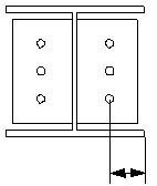
Bolt group dimensions

| Description | |
|---|---|
|
1 |
Number of bolts. |
|
2 |
Bolt spacing. Use a space to separate bolt spacing values. Enter a value for each space between bolts. For example, if there are 3 bolts, enter 2 values. |
|
3 |
Dimension for vertical bolt group position. |
|
4 |
Select how to measure the dimensions for vertical bolt group position.
|
|
5 |
Dimension for horizontal bolt group position. |
|
6 |
Select how to measure the dimensions for horizontal bolt group position.
|


Bolt basic properties
|
Option |
Description |
Default |
|---|---|---|
|
Bolt size |
Bolt diameter. |
Available sizes are defined in the bolt assembly catalog. |
|
Bolt standard |
Bolt standard to be used inside the component. |
Available standards are defined in the bolt assembly catalog. |
|
Tolerance |
Gap between the bolt and the hole. |
|
|
Thread in mat |
Defines whether the thread may be within the bolted parts when bolts are used with a shaft. This has no effect when full-threaded bolts are used. |
Yes |
|
Site/Workshop |
Location where the bolts should be attached. |
Site |
Slotted holes
You can define slotted, oversized, or tapped holes.

|
Option |
Description |
Default |
|---|---|---|
|
1 |
Vertical dimension of slotted hole. |
0, which results in a round hole. |
|
2 |
Horizontal dimension of slotted hole, or allowance for oversized holes. |
0, which results in a round hole. |
|
Hole type |
Slotted creates slotted holes. Oversized creates oversized or tapped holes. No hole does not create holes. |
|
|
Rotate Slots |
When the hole type is Slotted, this option rotates the slotted holes. |
|
|
Slots in |
Part(s) in which slotted holes are created. The options depend on the component in question. |
Bolt assembly
The selected check boxes define which component objects (bolt, washers, and nuts) are used in the bolt assembly.
If you want to create a hole only, clear all the check boxes.

To modify the bolt assembly in an existing component, select the Effect in modify check box and click Modify.
Bolt length increase
Define how much the bolt length is increased. Use this option when, for example, painting requires the bolt length to be increased.

Staggering of bolts
|
Option |
Description |
|---|---|
|
|
Default Not staggered AutoDefaults can change this option. |
|
|
Not staggered |
|
|
Staggered type 1 |
|
|
Staggered type 2 |
|
|
Staggered type 3 |
|
|
Staggered type 4 |
Chamfers tab
Use the Chamfers tab to define the chamfer types and dimensions for the haunch plate chamfers.
Chamfers
You can define each chamfer separately.

Holes tab
Use the Holes tab to define the holes created in the end plates.
Hole dimensions
You can define the holes separately for the main part end plate and the secondary part end plate. The main part end plate values are used as default values for the secondary part end plate.
| Option | Description |
|---|---|
|
|
Define the hole group dimensions in the rafter. |
|
|
Define the hole group dimensions in the haunch. |


| Option | Description |
|---|---|
|
Bolt standard |
Select the bolt standard. |
|
Bolt type |
Select the bolt type to define the location where the bolts should be attached. |
|
Read data from |
You can select to use the sinkholes.dat definition file to specify the default values for horizontal and vertical offsets, and the diameters for upper and lower holes. The file is searched in the following order: Environment common
system steel folder (..\Environments\common\system\Steel), model folder,
You can also select to define the holes in the component dialog box. |
General tab
Click the link below to find out more:
Design tab
Click the link below to find out more:
Analysis tab
Click the link below to find out more:
Welds
Click the link below to find out more: