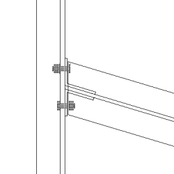
Bent plate (190)
Bent plate (190) connects two beams or a beam and a column using one or two bolted or welded bent plates. The secondary beam can be leveled or sloped and/or skewed. Welded haunch plates are optional.
Objects created
-
Bent plate (1 or 2)
-
Stiffeners (optional)
-
Top and bottom haunch plate (optional)
-
Weld backing bars (optional)
-
Bolts
-
Welds
-
Cuts
Use for
|
Situation |
Description |
|---|---|
|
|
Bent plate connecting two beams. The secondary part is skewed. |
|
|
Bent plate connected to a column flange. The secondary part is skewed. |
|
|
Bent plate connecting two beams. The secondary part is skewed. |
|
|
Bent plate connecting two beams. The secondary part is skewed. The plate can be placed to various locations. |
|
|
Bent plate connecting two beams. The secondary part is skewed and sloped. |
|
|
Bent plate connected to a column web. The secondary part is skewed. |


Selection order
-
Select the main part (beam or column).
-
Select the secondary part (beam). The connection is created automatically when the secondary part is selected.
Part identification key

|
Part |
|
|---|---|
|
1 |
Bent plate |
|
2 |
Haunch plate |
Note:
Tekla Structures uses values in the joints.def file to create this component.
Picture tab
Use the Picture tab to control the position of the bent plate and to define how the beam end is cut.
Dimensions

|
Description |
Default |
|
|---|---|---|
|
1 |
Cut length for the secondary part. The cutting point is defined from the bent plate edge. |
20 mm |
|
2 |
Bent plate upper edge distance from the top of the secondary part. The upper edge position of the plate modifies the bent plate height. Positive value moves the top position closer to the beam center and thus decreases the bent plate size. Negative value increases the bent plate size. |
If no value is entered, bolts and bolt edge distances define the size of the plate. |
|
3 |
Bent plate lower edge distance from the bottom of the secondary part. The lower edge position of the plate modifies the bent plate height. Positive value moves the bottom position closer to the beam center and thus decreases the plate size. Negative values increase the plate size. |
If no value is entered, bolts and bolt edge distances define the size of the plate. |
|
4 |
Size of the strip made to the secondary part flange. The cutting point of the flange is defined from the bent plate edge. |
The flange is automatically stripped when the bent plate crosses the flange. 10 mm |
|
5 |
Gap between the main part and the bent plate. |
0 |
Beam end cut
Define how the beam end is cut. The secondary part is viewed from the side.
|
Option |
Description |
|---|---|
|
|
Default Bevel AutoDefaults can change this option. |
|
|
Automatic If the secondary part slopes less than 10 degrees, a square cut is created. Otherwise, a bevel cut is made to the end of the secondary part. |
|
|
Square Creates a square cut to the end of the secondary part. |
|
|
Bevel Cuts the end of the secondary part parallel to the edge of the main part. |
Plates tab
Use the Plates tab to control the thickness, position and attachment of the bent plate. The dimensions on the Picture tab and the Bolts tab also affect the size of the bent plate.
Bent plate NS/FS
| Option |
Description |
|---|---|
|
Bent plate |
Bent plate thickness. |
|
Option |
Description |
Default |
|---|---|---|
|
Pos_No |
Prefix and start number for the part position number. Some components have a second row of fields where you can enter the assembly position number. |
The default part start number is defined in the Components settings in . |
|
Material |
Material grade. |
The default material is defined in the Part material box in the Components settings in . |
|
Name |
Name that is shown in drawings and reports. |
Bent plate position
|
Option |
Description |
|---|---|
|
|
Default Near side and far side bent plate AutoDefaults can change this option. |
|
|
Automatic Near side and far side bent plates are created automatically. |
|
|
Near side switched Creates a near side bent plate with a leg pointing to the far side. |
|
|
Far side switched Creates a far side bent plate with a leg pointing to the near side. |
|
|
Far side |
|
|
Near side |
|
|
Near side and far side |


Main and secondary part attachment type
|
Option |
Description |
|---|---|
|
|
Default Bent plate is bolted to the main part. AutoDefaults can change this option. |
|
|
Automatic Bolted |
|
|
Bolted |
|
|
Welded |
|
|
Bolted and welded |


Attachment point control
Define whether the bent plate is attached to the web or to the flange of the main part.

Bolt spacing and weld gap
|
Option |
Description |
|---|---|
|
|
Default Define the bolt spacing. Weld gap is not created. AutoDefaults can change this option. |
|
|
Define the bolt spacing. Weld gap is not created. |
|
|
Define the bolt spacing. Weld gap is created. |
|
|
Define the bolt spacing and the weld gap. |


Stiffeners tab
Use the Stiffeners tab to control the stiffener plate dimensions, orientation, position, and type.
Stiffener plate dimensions
| Option |
Description |
|---|---|
|
Top NS |
Top near side stiffener thickness, width and height. |
|
Top FS |
Top far side stiffener thickness, width and height. |
|
Bottom NS |
Bottom near side stiffener thickness, width and height. |
|
Bottom FS |
Bottom far side stiffener thickness, width and height. |
|
Option |
Description |
Default |
|---|---|---|
|
Pos_No |
Prefix and start number for the part position number. |
The default part start number is defined in the Components settings in . |
|
Material |
Material grade. |
The default material is defined in the Part material box in the Components settings in . |
|
Name |
Name that is shown in drawings and reports. |
Stiffener orientation
|
Option |
Description |
|---|---|
|
|
Default Stiffeners are parallel to the secondary part. AutoDefaults can change this option. |
|
|
Stiffeners are parallel to the secondary part. |
|
|
Stiffeners are perpendicular to the main part. |


Stiffener creation
|
Option |
Description |
|---|---|
|
|
Default Stiffeners are created. AutoDefaults can change this option. |
|
|
Automatic Stiffeners are created when necessary. |
|
|
No stiffeners are created. |
|
|
Stiffeners are created. |


Stiffener shape
|
Option |
Description |
|---|---|
|
|
Default Line chamfered stiffener plates AutoDefaults can change this option. |
|
|
Automatic Line chamfered stiffener plates |
|
|
Square stiffener plates Stiffener plates with a gap for the main part web rounding |
|
|
Line chamfered stiffener plates |


Stiffener gap
|
Option |
Description |
|---|---|
|
|
Size of the gap between the flanges and the stiffener. |

Stiffener positions

|
Description |
|
|---|---|
|
1 |
Size of the gap between the stiffener and the beam web edge. |
|
2 |
Size of the gap between the top near side stiffener and the beam flange edge. |
|
3 |
Size of the gap between the bottom near side stiffener and the beam flange edge. |
|
4 |
Size of the gap between the bottom far side stiffener and the beam flange edge. |
|
5 |
Size of the gap between the top far side stiffener and the beam flange edge. |
Chamfer dimensions

|
Description |
Default |
|
|---|---|---|
|
1 |
Vertical dimension of the chamfer. |
10 mm |
|
2 |
Horizontal dimension of the chamfer. |
10 mm |
Chamfer type
|
Option |
Description |
|---|---|
|
|
Default. Line chamfer AutoDefaults can change this option. |
|
|
No chamfer |
|
|
Line chamfer |
|
|
Convex arc chamfer |
|
|
Concave arc chamfer |


Haunch tab
Use the Haunch tab to control the haunch plate creation and chamfers in the secondary beam flanges.
Haunch plates
| Option |
Description |
|---|---|
|
Top plate |
Top haunch plate thickness, width and height. |
|
Bottom plate |
Bottom haunch plate thickness, width and height. |
|
Option |
Description |
Default |
|---|---|---|
|
Pos_No |
Prefix and start number for the part position number. |
The default part start number is defined in the Components settings in . |
|
Material |
Material grade. |
The default material is defined in the Part material box in the Components settings in . |
|
Name |
Name that is shown in drawings and reports. |
Haunch plate chamfers

|
Description |
|
|---|---|
|
1 |
Width of the top haunch plate chamfer. |
|
2 |
Height of the top haunch plate chamfer. |
|
3 |
Height of the bottom haunch plate chamfer. |
|
4 |
Width of the bottom haunch plate chamfer. |
Haunch plate creation
|
Option |
Description |
|---|---|
|
|
Default Top and bottom haunch plates are created, if needed. AutoDefaults can change this option. |
|
|
Automatic Top or bottom haunch plate or both are created, if needed. |
|
|
Top and bottom haunch plates are created. To create a single plate, enter 0 in the thickness (t) field for the plate you do not need (top or bottom plate). |
|
|
Haunch plates are not created. |


Notch tab
Use the Notch tab to automatically create notches for the secondary beams and to control the notch properties. The Notch tab has two sections: automatic properties (top section) and manual properties (bottom section). Automatic and manual notching properties work independently from each other.
Automatic notching
Automatic notching options affect both the top and the bottom flange.
Notch shape
Automatic notching is switched on when you select a notch shape.
|
Option |
Description |
|---|---|
|
|
Default Creates notches to the secondary beam. AutoDefaults can change this option. |
|
|
Creates notches to the secondary beam. The cuts are square to the main beam web. |
|
|
Creates notches to the secondary beam. The cuts are square to the secondary beam web. |
|
|
Creates notches to the secondary beam. The vertical cut is square to the main beam, and the horizontal cut is square to the secondary beam. |
|
|
Turns off automatic notching. |
Notch size
|
Option |
Description |
|---|---|
|
|
Default The notch size is measured from the edge of the main beam flange and from underneath the top flange of the main beam. AutoDefaults can change this option. |
|
|
The notch size is measured from the edge of the main beam flange and from underneath the top flange of the main beam. |
|
|
The notch size is measured from the center line of the main beam and from the top flange of the main beam. |
Enter the horizontal and vertical values for the cuts.

Flange cut shape
|
Option |
Description |
|---|---|
|
|
Default Secondary beam flange is cut parallel to the main beam. AutoDefaults can change this option. |
|
|
Secondary beam flange is cut parallel to the main beam. |
|
|
Secondary beam flange is cut square. |
Notch dimension rounding
Use the notch dimension rounding options to define whether the notch dimensions are rounded up. Even if the dimension rounding is set to active, the dimensions are rounded up only when necessary.
|
Option |
Description |
|---|---|
|
|
Default Notch dimensions are not rounded. AutoDefaults can change this option. |
|
|
Notch dimensions are not rounded. |
|
|
Notch dimensions are rounded. Enter the horizontal and vertical rounding values. |
The dimensions are rounded up the nearest multiple of the value you enter. For example, if the actual dimension is 51 and you enter a round-up value of 10, the dimension is rounded up to 60.

Notch position
|
Option |
Description |
|---|---|
|
|
Default Creates the cut below the main beam flange. AutoDefaults can change this option. |
|
|
Creates the cut below the main beam flange. |
|
|
Creates the cut above the main beam flange. |
Notch chamfer
|
Option |
Description |
|---|---|
|
|
Default The notch is not chamfered. AutoDefaults can change this option. |
|
|
The notch is not chamfered. |
|
|
Creates the notch with a line chamfer. |
|
|
The notch is chamfered according to the radius you enter. |
Enter a radius for the chamfer.
![]()
Manual notching
Use manual notching when a part that does not belong to the connection clashes with the secondary beam. When you use manual notching, the connection creates cuts using the values you enter in the fields on the Notch tab. You can use different values for the top and the bottom flange.
Side of flange notch
The side of flange notch defines on which side of the beam the notches are created.
|
Option |
Description |
|---|---|
|
|
Default Creates notches on both sides of the flange. AutoDefaults can change this option. |
|
|
Automatic Creates notches on both sides of the flange. |
|
|
Creates notches on both sides of the flange. |
|
|
Creates notches on the near side of the flange. |
|
|
Creates notches on the far side of the flange. |
Flange notch shape
The flange notch shape defines the notch shape in the beam flange.
|
Option |
Description |
|---|---|
|
|
Default The entire flange of the secondary beam is cut as far back as you define. AutoDefaults can change this option. |
|
|
Automatic The entire flange of the secondary beam is cut as far back as you define. The default depth for the notch is twice the thickness of the secondary flange. The cut always runs the entire width of the secondary flange. |
|
|
Creates chamfers in the flange. If you do not enter a horizontal dimension, a chamfer of 45 degrees is created. |
|
|
Creates cuts to the flange with default values unless you enter values in the fields 1and 2. |
|
|
The flange is not cut. |
|
|
Creates cuts to the flange according to the value in the field 1 to make it flush with the web. |
|
|
Creates cuts to the flange according to the values in the fields 1 and 2. |
Flange notch depth
|
Option |
Description |
|---|---|
|
|
Default Flange notch depth. AutoDefaults can change this option. |
|
|
Flange notch depth. |
|
|
Flange notch depth with a dimension from the secondary beam web center line to the edge of the notch. |


Enter the value for flange notch depth.
![]()
Cut dimensions

|
Description |
Default |
|
|---|---|---|
|
1 |
Dimensions for the horizontal flange cuts. |
10 mm |
|
2 |
Dimensions for the vertical flange cuts. |
The gap between the notch edge and the beam flange is equal to the main part web rounding. The notch height is rounded up to the nearest 5 mm. |
Bolts tab
Use the Bolts tab to control the properties of the bolts that connect the bent plate to the main part and to the secondary part.
Bolt group dimensions

|
Description |
|
|---|---|
|
1 |
Dimension for vertical bolt group position. |
|
2 |
Select how to measure the dimensions for vertical bolt group position.
|
|
3 |
Number of bolts. |
|
4 |
Bolt spacing. Use a space to separate bolt spacing values. Enter a value for each space between bolts. For example, if there are 3 bolts, enter 2 values. |
|
5 |
Bolt edge distance. Edge distance is the distance from the center of a bolt to the edge of the part. |


Staggering of bolts on bent plate
|
Option |
Description |
|---|---|
|
|
Default Bolts are not staggered. AutoDefaults can change this option. |
|
|
Bolts are not staggered. The bolts that connect the bent plate to the secondary part are on the same horizontal level as the bolts that connect the bent plate to the main part. |
|
|
Bolts on the main part are staggered. The bolts that connect the bent plate to the main part are moved downwards by half the bolt vertical spacing value. |
|
|
Bolts on the secondary part are staggered. The bolts that connect the bent plate to the secondary part are moved downwards by half the bolt vertical spacing value. |
|
|
Bolts on the secondary part are staggered. The bolts that connect the bent plate to the sloped secondary part are parallel to the secondary part. |
Bolt group dimensions

|
Description |
|
|---|---|
|
1 |
Define which bolts are deleted from the bolt group. Enter the bolt numbers of the bolts to be deleted and separate the numbers with a space. Bolt numbers run from left to right and from top to bottom. |
|
2 |
Number of bolts. |
|
3 |
Bolt spacing. Use a space to separate bolt spacing values. Enter a value for each space between bolts. For example, if there are 3 bolts, enter 2 values. |
|
4 |
Bolt edge distance. |
|
5 |
Location where the bolts should be attached. |
Staggering of bolts
|
Option |
Description |
|---|---|
|
|
Default Not staggered AutoDefaults can change this option. |
|
|
Not staggered |
|
|
Staggered type 1 |
|
|
Staggered type 2 |
|
|
Staggered type 3 |
|
|
Staggered type 4 |
Bolt basic properties
|
Option |
Description |
Default |
|---|---|---|
|
Bolt size |
Bolt diameter. |
Available sizes are defined in the bolt assembly catalog. |
|
Bolt standard |
Bolt standard to be used inside the component. |
Available standards are defined in the bolt assembly catalog. |
|
Tolerance |
Gap between the bolt and the hole. |
|
|
Thread in mat |
Defines whether the thread may be within the bolted parts when bolts are used with a shaft. This has no effect when full-threaded bolts are used. |
Yes |
|
Site/Workshop |
Location where the bolts should be attached. |
Site |
Slotted holes
You can define slotted, oversized, or tapped holes.

|
Option |
Description |
Default |
|---|---|---|
|
1 |
Vertical dimension of slotted hole. |
0, which results in a round hole. |
|
2 |
Horizontal dimension of slotted hole, or allowance for oversized holes. |
0, which results in a round hole. |
|
Hole type |
Slotted creates slotted holes. Oversized creates oversized or tapped holes. No hole does not create holes. |
|
|
Rotate Slots |
When the hole type is Slotted, this option rotates the slotted holes. |
|
|
Slots in |
Part(s) in which slotted holes are created. The options depend on the component in question. |
Bolt assembly
The selected check boxes define which component objects (bolt, washers, and nuts) are used in the bolt assembly.
If you want to create a hole only, clear all the check boxes.

To modify the bolt assembly in an existing component, select the Effect in modify check box and click Modify.
Bolt length increase
Define how much the bolt length is increased. Use this option when, for example, painting requires the bolt length to be increased.

Beam cut tab
Use the Beam cut tab to control weld backing bars, weld access holes, beam end preparations, and flange cuts.
Weld backing bar
| Option |
Description |
|---|---|
|
Weld backing bar |
Weld backing bar thickness and width. |
|
Option |
Description |
Default |
|---|---|---|
|
Pos_No |
Prefix and start number for the part position number. Some components have a second row of fields where you can enter the assembly position number. |
The default part start number is defined in the Components settings in . |
|
Material |
Material grade. |
The default material is defined in the Part material box in the Components settings in . |
|
Name |
Name that is shown in drawings and reports. |
Weld access hole dimensions

|
Description |
|
|---|---|
|
1 |
Gap between the secondary part top flange and the main part. |
|
2 |
Vertical dimensions for the top and the bottom weld access holes. |
|
3 |
Horizontal dimensions for the top and the bottom weld access holes. |
|
4 |
Gap between the secondary part web and the main part. Tekla Structures adds the value you enter here to the gap you enter on the Picture tab. |
|
5 |
Gap between the secondary part bottom flange and the main part. Tekla Structures adds the value you enter here to the gap you enter on the Picture tab. |
Weld access holes
|
Option |
Description |
Default |
|---|---|---|
|
|
Default Round weld access hole AutoDefaults can change this option. |
|
|
|
Round weld access hole |
|
|
|
Square weld access hole |
|
|
|
Diagonal weld access hole |
|
|
|
Round weld access hole with a radius that you can define in
|
|
|
|
Extended cone-shaped weld access hole with a radius and dimensions that you can define in
|
|
|
|
Cone-shaped weld access hole with radiuses that you can define in
Capital R defines the large radius (height). Small r defines the small radius. |
R = 35 r = 10 |

Beam end preparation
|
Option |
Description |
|---|---|
|
|
Default Top and bottom flange are prepared. AutoDefaults can change this option. |
|
|
Automatic Top and bottom flange are prepared. |
|
|
Beam end is not prepared. |
|
|
Top and bottom flange are prepared. |
|
|
Top flange is prepared. |
|
|
Bottom flange is prepared. |
Flange cut
|
Option for top flange |
Option for bottom flange |
Description |
|---|---|---|
|
|
|
Default Flange is not cut. AutoDefaults can change this option. |
|
|
|
Flange is not cut. |
|
|
|
Flange is cut. |
Weld backing bars
|
Option for top backing bar |
Option for bottom backing bar |
Description |
|---|---|---|
|
|
|
Default Backing bars are created inside the flanges. AutoDefaults can change this option. |
|
|
|
No backing bars are created. |
|
|
|
Backing bars are created inside the flanges. |
|
|
|
Backing bars are created outside the flanges. |
Weld backing bar length
Enter the length of the weld backing bar in the box below the options.
|
Option |
Description |
|---|---|
|
|
Default Absolute length of the backing bar AutoDefaults can change this option. |
|
|
Absolute length of the backing bar |
|
|
Extension beyond the edge of the flange |
Weld backing bar position
|
Option |
Description |
|---|---|
|
|
Enter a positive or a negative value to move the front end of the backing bar relative to the end of the flange. |

Assembly type
Define the location where the weld backing bar welds are made. When you select the Workshop option, Tekla Structures includes the backing bars in the assembly.
General tab
Click the link below to find out more:
Design tab
Click the link below to find out more:
Analysis tab
Click the link below to find out more:
Welds
Click the link below to find out more: