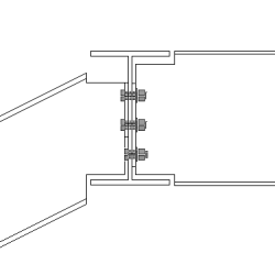
Two sided end plate (142)
Two sided end plate (142) connects two beams to a beam or to a column using bolted end plates. One bolt group goes through all the three parts.
Objects created
-
End plates
-
Shim plates
-
Compensating flange plates (optional)
-
Haunch plates (optional)
-
Holes
-
Bolts
-
Welds
-
Cuts
Use for
|
Situation |
Description |
|---|---|
|
|
End plate connection with two secondary parts. Automatic notching for bolt clearance. |
|
|
End plate connection with two secondary parts and with a haunch plate. Automatic notching for bolt clearance. |
|
|
End plate connection with two secondary parts at different heights. |
|
|
End plate connection with two secondary parts. The secondary parts can be square and/or skewed. |
|
|
End plate connection with two secondary parts. Safety connection. |
|
|
End plate connection with two secondary parts. The secondary parts can be leveled and/or sloped. |


Selection order
-
Select the main part (column or beam).
-
Select the first secondary part (beam).
-
Select the second secondary part (beam).
-
Click the middle mouse button to create the connection.
Part identification key

|
Part |
|
|---|---|
|
1 |
End plate for the first secondary part |
|
2 |
Shim plate for the first secondary part |
|
3 |
End plate for the second secondary part |
|
4 |
Shim plate for the second secondary part |
|
5 |
Compensating flange plate for the first secondary part |
|
6 |
Compensating flange plate for the second secondary part |
Note:
Tekla Structures uses values in the joints.def file to create this component.
Picture tab
Use the Picture tab to control the positions of the end plates and compensating flange plates.
Plate positions

|
Description |
|
|---|---|
|
1 |
End plate upper edge distance from the top of the first secondary beam. |
|
2 |
End plate lower edge distance from the bottom of the first secondary beam. |
|
3 |
End plate lower edge distance from the bottom of the second secondary beam. |
|
4 |
End plate upper edge distance from the top of the second secondary beam. |
|
5 |
Gap between the shim plates and the main part. Gap for each side individually. If the shim plates are not used, the defined gap is created between the end plate and the main part. |
|
6 |
Upper compensation flange plate edge distance from the top of the first secondary beam. |
|
7 |
Lower compensation flange plate edge distance from the top of the first secondary beam. |
|
8 |
Upper compensation flange plate edge distance from the top of the second secondary beam. |
|
9 |
Lower compensation flange plate edge distance from the top of the first secondary beam. |
Compensation flange plate arrangements
| Option | Description |
|---|---|
|
|
Default Compensation flange plates are not created. AutoDefaults can change this option. |
|
|
Compensation flange plates are not created. |
|
|
Compensation flange plates are created. Egde distance from the top of the secondary part. |
|
|
Compensation flange plates are created. Edge distance from the top of the main part. |


Compensating flange plate shapes

| Description | |
|---|---|
|
1 |
Compensating flange plate dimension that remains when a chamfer is created. |
|
2 |
Horizontal chamfer dimension of the compensating flange plate. |
|
3 |
Inner chamfer dimension of the compensating flange plate. |
Sort secondaries by profile height
When you create a Two sided end plate (142) connection, the larger of the two profiles is usually selected as the first secondary beam. If the profile is later changed and the second secondary beam becomes larger than the first secondary beam, the order of secondary beams can be redefined.
-
Yes switches the secondary beams so that the largest beam automatically becomes the first secondary beam.
-
No does not change the order of secondary beams if the profile size is changed.
Plates 1 tab
Use the Plates 1 tab to control the size of the end plate, shim plates and compensating flange plates for the first secondary beam.
Plates
| Option |
Description |
Default |
|---|---|---|
|
End plate |
End plate thickness, width and height. |
thickness = 10 mm |
|
Fitting Plate 1 Fitting Plate 2 Fitting Plate 3 |
Shim plate thickness. The plate is created only if the plate thickness is given. You can define up to three different shim plates. |
0 |
|
Number of fitting pl. 1 (DEF=1) Number of fitting pl. 2 (DEF=1) Number of fitting pl. 3 (DEF=1) |
Number of shim plates for each thickness. |
By default, 1 plate is created. |
|
Comp. flange pl |
Compensation flange plate thickness, width and height. |
|
Option |
Description |
Default |
|---|---|---|
|
Pos_No |
Prefix and start number for the part position number. Some components have a second row of fields where you can enter the assembly position number. |
The default part start number is defined in the Components settings in . |
|
Material |
Material grade. |
The default material is defined in the Part material box in the Components settings in . |
|
Name |
Name that is shown in drawings and reports. |
|
|
Finish |
Describes how the part surface has been treated. |
Bolt edge distances in shim plate
Define the bolt edge distances for shim plates. When these fields are empty, shim plates are of the same size as the end plate.

|
Description |
Default |
|
|---|---|---|
|
1 |
Horizontal bolt edge distance in the shim plate. |
30 mm |
|
2 |
Vertical bolt edge distance in the shim plate. |
30 mm |
Shim plate shape
| Option | Description |
|---|---|
|
|
Default Holes are based on the bolt group of the connection. AutoDefaults can change this option. |
|
|
Holes are based on the bolt group of the connection. |
|
|
Finger shim plate with horizontal slots. The plate can be installed from the right or the left side of the connection. |
|
|
Finger shim plate with vertical slots. The plate can be installed from the top of the connection. |
|
|
Two separate finger shim plates with horizontal slots. |
|
|
Two separate finger shim plates with vertical slots. |


Tolerance
Define the tolerance for the slots in finger shim plates. The width of the slot is the bolt diameter + the tolerance. For two separate shim plates, also define the tolerance between the plates.
Shim plate position
|
Option |
Description |
|---|---|
|
|
Default Shim plates are outside the main part. AutoDefaults can change this option. |
|
|
Shim plates are outside the main part. |
|
|
Shim plates are inside the main part. |


Gap size

Define the limit value for the gap between the end plate and the secondary beam. Use this when the beam is slightly curved or sloped to decide if the end angle is so small that the beam end can be straight.
If the actual gap is smaller than this value, the end of the beam is left straight.
If the actual gap is larger than this value, the end of the beam is fitted to the end plate.
Safety connections
In two-sided connections the safety connection options improve safety during erection. Safety connection options move the end plate or create different notches so that some of the bolts are in single shear instead of double shear. This allows the first secondary beam to be connected while the crane moves to get the next beam.
|
Option |
Description |
|---|---|
|
|
Default End plate with no notches. AutoDefaults can change this option. |
|
|
End plate with no notches. |
|
|
One end plate is moved up to create a safety connection. |
|
|
One end plate is moved down to create a safety connection. |
|
|
One opposite upper corner of each end plate is notched to create a safety connection |
|
|
One opposite upper corner of each end plate is notched to create a safety connection. |
|
|
Diagonal opposite corners of each end plate are notched to create a safety connection. |
|
|
Diagonal opposite corners of each end plate are notched to create a safety connection. |


Safety connection location
|
Option |
Description |
|---|---|
|
|
Default Affects both the near side and the far side end plates. AutoDefaults can change this option. |
|
|
Affects both the near side and the far side end plates. |
|
|
Affects only the near side end plate. |
|
|
Affects only the far side end plate. |


Safety connection cut type
|
Option |
Description |
|---|---|
|
|
Default Square cut. This selection affects only safety connections that are created with cuts. It does not affect safety connections that shorten the plate. AutoDefaults can change this option. |
|
|
Square cut |
|
|
Line cut |
|
|
Concave arc cut |


Safety connection cut dimensions
| Option | Description |
|---|---|
|
Vertical cut/offset |
Define the height of the notch or the vertical offset of the end plate. |
|
Horizontal cut |
Define the width of the notch in the end plate. |
|
Radius |
Define the radius of the concave arc cut. |
Plates 2 tab
Use the Plates 2 tab to control the size of the end plate, shim plates and compensating flange plates for the second secondary beam.
Plates
| Option |
Description |
Default |
|---|---|---|
|
End plate |
End plate thickness, width and height. |
thickness = 10 mm |
|
Fitting Plate 1 Fitting Plate 2 Fitting Plate 3 |
Shim plate thickness. The plate is created only if the plate thickness is given. You can define up to three different shim plates. |
0 |
|
Number of fitting pl. 1 (DEF=1) Number of fitting pl. 2 (DEF=1) Number of fitting pl. 3 (DEF=1) |
Number of shim plates for each thickness. |
By default, 1 plate is created. |
|
Comp. flange pl |
Compensation flange plate thickness, width and height. |
|
Option |
Description |
Default |
|---|---|---|
|
Pos_No |
Prefix and start number for the part position number. Some components have a second row of fields where you can enter the assembly position number. |
The default part start number is defined in the Components settings in . |
|
Material |
Material grade. |
The default material is defined in the Part material box in the Components settings in . |
|
Name |
Name that is shown in drawings and reports. |
|
|
Finish |
Describes how the part surface has been treated. |
Bolt edge distances in shim plate
Define the bolt edge distances for shim plates. When these fields are empty, shim plates are of the same size as the end plate.
|
Description |
Default |
|
|---|---|---|
|
1 |
Horizontal bolt edge distance in the shim plate. |
30 mm |
|
2 |
Vertical bolt edge distance in the shim plate. |
30 mm |
Shim plate shape
|
Option |
Description |
|---|---|
|
|
Default Holes are based on the bolt group of the connection. AutoDefaults can change this option. |
|
|
Holes are based on the bolt group of the connection. |
|
|
Finger shim plate with horizontal slots. The plate can be installed from the right or the left side of the connection. |
|
|
Finger shim plate with vertical slots. The plate can be installed from the top of the connection. |
|
|
Two separate finger shim plates with horizontal slots. |
|
|
Two separate finger shim plates with vertical slots. |
Tolerance
Define the tolerance for the slots in finger shim plates. The width of the slot is the bolt diameter + the tolerance. For two separate shim plates, also define the tolerance between the plates.
Shim plate position
|
Option |
Description |
|---|---|
|
|
Default Shim plates are outside the main part. AutoDefaults can change this option. |
|
|
Shim plates are outside the main part. |
|
|
Shim plates are inside the main part. |


Gap size
Define the limit value for the gap between the end plate and the secondary beam. Use this when the beam is slightly curved or sloped to decide if the end angle is so small that the beam end can be straight.
If the actual gap is smaller than this value, the end of the beam is left straight.
If the actual gap is larger than this value, the end of the beam is fitted to the end plate.
Shim plate and end plate positions
Define the position of the shim plates and the end plate in the second secondary beam. The plates move in relation to the plates in the first secondary beam. By default, the plates in the second secondary beam are positioned so that holes are placed symmetrically. You may need to move the plates, for example, when connecting skew or curved secondary beams.

|
Description |
|
|---|---|
|
1 |
Define how much the plates are moved in vertical direction. |
|
2 |
Define how much the plates are moved in horizontal direction. |
Haunch tab
Use the Haunch tab to control the haunch plate creation and chamfers in the secondary beam flanges.
Haunch plates
| Option | Description |
|---|---|
|
Top plate, Top plate 2 |
Top haunch plate thickness, width and height. |
|
Bottom plate, Bottom plate 2 |
Bottom haunch plate thickness, width and height. |
|
Option |
Description |
Default |
|---|---|---|
|
Pos_No |
Prefix and start number for the part position number. Some components have a second row of fields where you can enter the assembly position number. |
The default part start number is defined in the Components settings in . |
|
Material |
Material grade. |
The default material is defined in the Part material box in the Components settings in . |
|
Name |
Name that is shown in drawings and reports. |
|
|
Finish |
Describes how the part surface has been treated. |
Haunch plate creation
|
Option for the second secondary beam |
Option for the first secondary beam |
Description |
|---|---|---|
|
|
|
Default Top and bottom haunch plates are created, if needed. AutoDefaults can change this option. |
|
|
|
Automatic Top or bottom haunch plate or both are created, if needed. |
|
|
|
Top and bottom haunch plates are always created. To create a single plate, enter 0 in the thickness (t) field for the haunch plate you do not need (top or bottom plate). |
|
|
|
Haunch plates are not created. |


Haunch plate chamfers

|
Description |
|
|---|---|
|
1 |
Width of the top haunch plate chamfer. |
|
2 |
Height of the top haunch plate chamfer. |
|
3 |
Height of the bottom haunch plate chamfer. |
|
4 |
Width of the bottom haunch plate chamfer. |
Notch tab
Use the Notch tab to automatically create notches for the secondary beams and to control the notch properties. The Notch tab has two sections: automatic properties (top section) and manual properties (bottom section). Automatic and manual notching properties work independently from each other.
Automatic notching
Automatic notching options affect both the top and the bottom flange.
Notch shape
Automatic notching is switched on when you select a notch shape.
|
Option |
Description |
|---|---|
|
|
Default Creates notches to the secondary beam. AutoDefaults can change this option. |
|
|
Creates notches to the secondary beam. The cuts are square to the main beam web. |
|
|
Creates notches to the secondary beam. The cuts are square to the secondary beam web. |
|
|
Creates notches to the secondary beam. The vertical cut is square to the main beam, and the horizontal cut is square to the secondary beam. |
|
|
Turns off automatic notching. |
Notch size
|
Option |
Description |
|---|---|
|
|
Default The notch size is measured from the edge of the main beam flange and from underneath the top flange of the main beam. AutoDefaults can change this option. |
|
|
The notch size is measured from the edge of the main beam flange and from underneath the top flange of the main beam. |
|
|
The notch size is measured from the center line of the main beam and from the top flange of the main beam. |
Enter the horizontal and vertical values for the cuts.

Flange cut shape
|
Option |
Description |
|---|---|
|
|
Default Secondary beam flange is cut parallel to the main beam. AutoDefaults can change this option. |
|
|
Secondary beam flange is cut parallel to the main beam. |
|
|
Secondary beam flange is cut square. |
Notch dimension rounding
Use the notch dimension rounding options to define whether the notch dimensions are rounded up. Even if the dimension rounding is set to active, the dimensions are rounded up only when necessary.
|
Option |
Description |
|---|---|
|
|
Default Notch dimensions are not rounded. AutoDefaults can change this option. |
|
|
Notch dimensions are not rounded. |
|
|
Notch dimensions are rounded. Enter the horizontal and vertical rounding values. |
The dimensions are rounded up the nearest multiple of the value you enter. For example, if the actual dimension is 51 and you enter a round-up value of 10, the dimension is rounded up to 60.

Notch position
|
Option |
Description |
|---|---|
|
|
Default Creates the cut below the main beam flange. AutoDefaults can change this option. |
|
|
Creates the cut below the main beam flange. |
|
|
Creates the cut above the main beam flange. |
Notch chamfer
|
Option |
Description |
|---|---|
|
|
Default The notch is not chamfered. AutoDefaults can change this option. |
|
|
The notch is not chamfered. |
|
|
Creates the notch with a line chamfer. |
|
|
The notch is chamfered according to the radius you enter. |
Enter a radius for the chamfer.
![]()
Manual notching
Use manual notching when a part that does not belong to the connection clashes with the secondary beam. When you use manual notching, the connection creates cuts using the values you enter in the fields on the Notch tab. You can use different values for the top and the bottom flange.
Side of flange notch
The side of flange notch defines on which side of the beam the notches are created.
|
Option |
Description |
|---|---|
|
|
Default Creates notches on both sides of the flange. AutoDefaults can change this option. |
|
|
Automatic Creates notches on both sides of the flange. |
|
|
Creates notches on both sides of the flange. |
|
|
Creates notches on the near side of the flange. |
|
|
Creates notches on the far side of the flange. |
Flange notch shape
The flange notch shape defines the notch shape in the beam flange.
|
Option |
Description |
|---|---|
|
|
Default The entire flange of the secondary beam is cut as far back as you define. AutoDefaults can change this option. |
|
|
Automatic The entire flange of the secondary beam is cut as far back as you define. The default depth for the notch is twice the thickness of the secondary flange. The cut always runs the entire width of the secondary flange. |
|
|
Creates chamfers in the flange. If you do not enter a horizontal dimension, a chamfer of 45 degrees is created. |
|
|
Creates cuts to the flange with default values unless you enter values in the fields 1and 2. |
|
|
The flange is not cut. |
|
|
Creates cuts to the flange according to the value in the field 1 to make it flush with the web. |
|
|
Creates cuts to the flange according to the values in the fields 1 and 2. |
Flange notch depth
|
Option |
Description |
|---|---|
|
|
Default Flange notch depth. AutoDefaults can change this option. |
|
|
Flange notch depth. |
|
|
Flange notch depth with a dimension from the secondary beam web center line to the edge of the notch. |


Enter the value for flange notch depth.
![]()
Cut dimensions

|
Description |
Default |
|
|---|---|---|
|
1 |
Dimensions for the horizontal flange cuts. |
10 mm |
|
2 |
Dimensions for the vertical flange cuts. |
The gap between the notch edge and the beam flange is equal to the main part web rounding. The notch height is rounded up to the nearest 5 mm. |
BCSA notch definition
Define whether the notch is created according to British Constructional Steelwork Association (BCSA) specifications.
|
Option |
Description |
|---|---|
|
Default |
Notch dimensions. |
|
Yes |
Creates a 50 mm notch for simple beam-to-beam connections. |
|
No |
Use the options on this Notch tab to define the notch dimensions. |
Bolts tab
Use the Bolts tab to control the properties of bolts that connect the end plates to the main part.
Bolt group dimensions
Bolt group dimensions affect the size of the end plates.

| Description | |
|---|---|
| 1 |
Dimension for vertical bolt group position. |
| 2 |
Select how to measure the dimensions for vertical bolt group position.
|
| 3 |
Bolt edge distance. Edge distance is the distance from the center of a bolt to the edge of the part. |
| 4 |
Number of bolts. |
| 5 |
Bolt spacing. Use a space to separate bolt spacing values. Enter a value for each space between bolts. For example, if there are 3 bolts, enter 2 values. |
| 6 |
Dimension for horizontal bolt group position. |
| 7 |
Select how to measure the dimensions for horizontal bolt group position.
|
| 8 |
Define which bolts are deleted from the bolt group. Enter the bolt numbers of the bolts to be deleted and separate the numbers with a space. Bolt numbers run from left to right and from top to bottom. |


Bolt basic properties
|
Option |
Description |
Default |
|---|---|---|
|
Bolt size |
Bolt diameter. |
Available sizes are defined in the bolt assembly catalog. |
|
Bolt standard |
Bolt standard to be used inside the component. |
Available standards are defined in the bolt assembly catalog. |
|
Tolerance |
Gap between the bolt and the hole. |
|
|
Thread in mat |
Defines whether the thread may be within the bolted parts when bolts are used with a shaft. This has no effect when full-threaded bolts are used. |
Yes |
|
Site/Workshop |
Location where the bolts should be attached. |
Site |
Cut length
Defines the depth at which Tekla Structures searches for the sections of the bolted parts. You can determine whether the bolt will go through one flange or two.
Bolt comment
You can define a bolt comment.
Slotted holes
You can define slotted, oversized, or tapped holes.

|
Option |
Description |
Default |
|---|---|---|
|
1 |
Vertical dimension of slotted hole. |
0, which results in a round hole. |
|
2 |
Horizontal dimension of slotted hole, or allowance for oversized holes. |
0, which results in a round hole. |
|
Hole type |
Slotted creates slotted holes. Oversized creates oversized or tapped holes. No hole does not create holes. |
|
|
Rotate Slots |
When the hole type is Slotted, this option rotates the slotted holes. |
|
|
Slots in |
Part(s) in which slotted holes are created. The options depend on the component in question. |
Bolt assembly
The selected check boxes define which component objects (bolt, washers, and nuts) are used in the bolt assembly.
If you want to create a hole only, clear all the check boxes.

To modify the bolt assembly in an existing component, select the Effect in modify check box and click Modify.
Bolt length increase
Define how much the bolt length is increased. Use this option when, for example, painting requires the bolt length to be increased.

Holes tab
Use the Holes tab to control the galvanizing holes in the end plates.
| Option | Description |
|---|---|
|
Bolt standard |
Select the bolt standard. |
|
Bolt type |
Select the bolt type to define the location where the bolts should be attached. |
|
Read data from |
You can select to use the sinkholes.dat definition file to specify the default values for horizontal and vertical offsets, and the diameters for upper and lower holes. The file is searched in the following order: Environment common
system steel folder (..\Environments\common\system\Steel), model folder,
You can also select to define the holes in the component dialog box. |
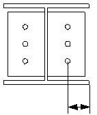
Number of holes
The center of a hole group is the middle point of the beam and the middle point of the haunch, if the haunch exists. The hole groups are composed of 0, 1, 2 or 4 holes.
|
Option for the first secondary beam |
Option for the second secondary beam |
Description |
|---|---|---|
|
|
|
Default No holes AutoDefaults can change this option. |
|
|
|
No holes |
|
|
|
1 hole |
|
|
|
2 holes |
|
|
|
4 holes |


Hole positions
Hole positions in the end plate of the first secondary beam.

Hole positions in the end plate of the second secondary beam.

|
Description |
|
|---|---|
|
1 |
Horizontal distance between the secondary beam center and the upper hole. |
|
2 |
Horizontal distance between the secondary beam center and the lower hole. |
|
3 |
Vertical distance between the secondary beam center and the upper hole. |
|
4 |
Vertical distance between the secondary beam center and the lower hole. |
|
5 |
Diameter of the lower hole. |
|
6 |
Diameter of the upper hole. |
General tab
Click the link below to find out more:
Design type tab
Click the link below to find out more:
Analysis tab
Click the link below to find out more:
Welds
Click the link below to find out more: