Column base plate design workflow
Note: To find out more about the theory,
assumptions and checks performed for the head code being worked to, see: Column base plate design to AISC 360 or Column base plate design to EC3.
Data sources
Whilst all column base plate data is held in the model, the source of such data is several fold. This includes:
-
Default data - when the column base plates within the model are set up by Tekla Structural Designer, intelligent defaults are used that can establish a part or full solution to the configuration.
-
Derived data - the model already holds such items as the section size and grade of the column and concrete foundation, plus the design forces.
-
Property Sets - certain data can be set to be used to modify existing properties of the column base plates e.g. base plate steel grade, bolt size etc. For more information, see: Manage properties and property setsNote: If a concrete base is already modeled below a base plate then the concrete base properties Length, Width, Depth, and Concrete (grade) will not be modified when applying a base plate property set.
-
Added data - any individual column base plate can be edited to improve or add to the configuration e.g. additional bolts.
Generate base plates
When a steel column is created or copied a base plate is automatically generated at the lower end of the column if a support is required.
Base plates can also be created by clicking the (Add) Base Plate button on the Design ribbon and then selecting a steel column in the model. Note that moving a steel column that already has a base plate attached will automatically move the attached base plate with it.
Design columns
Base plates have the capability of automatically sizing when the column size changes.
This Autosize option, which is on as default, will update the plate size and the bolt layout when the column size changes to avoid an invalid base plate configuration. This is not to be confused with automatic design of the base plate which is beyond the scope of Tekla Structural Designer.
Edit base plate properties
Once the associated columns are sized it’s possible to turn off Autosize and start to finalize the base plate configuration.
This is easily done based on the column size by navigating to Structure Tree > Members > Base Plates and selecting the column size.
You can then adjust the column base plate properties in the Properties window.
Alternatively, and also for more complex bolt/rod layouts, you can right click an individual base plate and select Edit from the context menu, which opens an Edit dialog for all of the base plate properties.
You can see whether your base plate configuration looks sensible by display in the Structure 3D view.
To copy, move or delete base plates
-
Base plates can be moved/copied/deleted independently of the column they are associated to as long as the target location is the bottom of a valid column.
-
Base plates can be moved/copied/deleted with the associated column.
-
By simply selecting the column to move/copy/delete the base plate, as default, will be selected too.
-
You can chose to only move/copy/delete the column by de-selecting the base plate from the usual dialog.
-
Check base plates
Having established and rationalized the base plate configurations it is now logical to carry out a design check.
You can check an individual base plate, or a selection of base plates and adjust them as you proceed or, once you are content with the layout, you can check them all in a single operation:
-
To check an individual base plate - select it in the model (or in the Structure Tree), right-click to display the context menu and select Check Base Plate
-
To check a selection of base plates - navigate to the Structure Tree > Members > Base Plates, select the column size to check, right-click and select Check Base Plates
-
To check all base plates in the model - go to the Design tab and select Check Base Plates
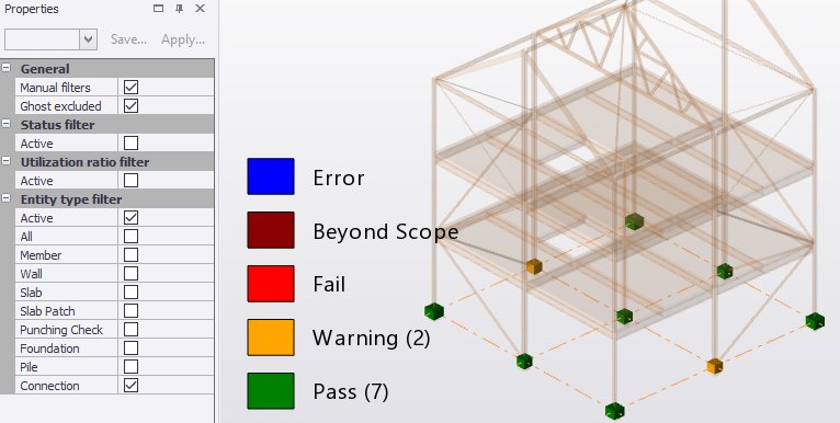
Review check status and utilization
You can then use Review View to visually check
which column base plates have passed and which have not, and their associated
utilization ratios.
View results and print calculations
Results of your column base plate checks can be viewed on the screen by right clicking on a base plate and selecting Check Base Plate from the context menu.
When you are ready to create a report:
- if you require the input, diagrams, and design results you should incorporate the Base Plates chapter,
- if you only require a summary of base plate design check calculations you should include the Base Plate Design Summary chapter. (The default Building Design report includes this along with design calculations for other member types in the model).
- if you require a material list containing base plate components, for example rods (US), or bolts (Eurocode), and anchor plates, these are listed in the Material Listing report, as well as the plates themselves, but not the welds.
Create drawings
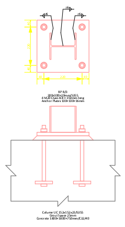
Base plate detail drawings that convey the structural intent are easy to create. It should be borne in mind that these are NOT the final detail drawings, their purpose is to eliminate the need for manual mark-up drawings as a means of communication between the engineer and the detailer.