Seating with dowel (75)
Seating with dowel (75) connects a column and a beam using an anchor bolt.
Parts created
-
Anchor bolt
-
Nut
-
Washer plate
-
Bearing plate
-
Fittings for beam and column
-
Hole for bolt
-
Corbel (optional)
-
Recess for nut and washer plate (optional)
Use for
| Situation | Description |
|---|---|
|
|
Connects a beam and a column using an anchor bolt. Washer plate and nut protrude from the beam. |
|
|
Connects a beam and a column using an anchor bolt and a beveled corbel. Washer plate and nut recessed into the beam. |


Before you start
Create the following parts:
-
Concrete column (round or rectangular profile)
-
Concrete beam (rectangular, HI, I, L, or inverted T profile)
Selection order
-
Select the main part (column).
-
Select the secondary part (beam).
The connection is created automatically when the second part is selected.
Picture tab
Use the Picture tab to define position of anchor bolt and bearing plate, bolt hole dimensions, grout type, and beam clearance.
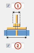
Bolt hole
Enter the following bolt hole dimensions:

|
Description |
|
|---|---|
|
1 |
Hole dimension in the direction of the beam. |
|
2 |
The distance from beam center line to hole center and bolt. |
|
3 |
Hole dimension in the direction perpendicular to the beam. |
Select the shape of the bolt hole:
|
Option |
Description |
|---|---|
|
|
Rectangular Default |
|
|
Round |


Beam and column
Select one of the following options to have Tekla Structures fit the column or the beam:
|
Option |
Description |
|---|---|
|
|
Fits the column. Default |
|
|
Fits the beam. The beam must be sloped. |


Bearing plate
Select one of the following options to define the position of the bearing plate:
|
Option |
Description |
|---|---|
|
|
Square with beam. Default |
|
|
Square with column. |
|
|
Square with column. Enter the distances from column edges. |


Dowel tab
Use the Dowel tab to define dowel and grout properties.
Dowel
|
Option |
Description |
|---|---|
|
Profile |
Select the dowel profile from the profile catalog. |
|
Prefix, Start number |
Prefix and start number for the part position number. |
|
Material |
Material grade. The default material is defined in the Part material box in the Components settings in . |
|
Name |
Name that is shown in drawings and reports. |
|
Finish |
Describes how the part surface has been treated. |
|
Class |
Enter a number to group the parts that the component creates. By default, the class number affects the color in which the part is shown in model views. |
|
Size |
Diameter of the bars. |
|
Grade |
Strength of the steel used in the bars. |
|
Number of bars |
Select 1 Dowel to create one reinforcing bar. Select 2 Dowels to create two reinforcing bars. Then define the distance between the bars in the Bar distance field. |
Grout
Select one of the following options to include and define grout:
|
Option |
Description |
|---|---|
|
|
No grout. Default |
|
|
Bolt hole grouted. No nut or washer plate. |
|
|
Bolt hole grouted. Bolt, washer plate, and anchor bolt protruding. |


Nut and washer plate
Select one of the following options to define if the nut and washer plate are recessed into the beam:
|
Option |
Description |
|---|---|
|
|
Nut and washer plate on the surface of the beam. Default |
|
|
Nut and bolt plate recessed into the beam. |


If you choose to recess the nut and washer plate into the beam, enter the following dimensions to define the recess:

Parts tab
Use the Parts tab to define bearing pad, drainage hole, grout, bolt plate, nut, and tube properties.
|
Option |
Description |
|---|---|
|
t, b, h |
Define the part thickness, width and height. |
|
Pos_No |
Define a prefix and a start number for the part position number. |
|
Material |
Define the material grade. |
|
Name |
Define a name for the part. |
|
Class |
Use Class to group the parts. |
|
Cast unit |
Select to add the parts to the cast unit. |
Nut and bolt plate
|
Field |
Description |
|---|---|
|
1 |
Nut width. |
|
2 |
Bolt plate width. |
Corbel tab
Use the Corbel tab to create a corbel and define its properties.
Select to create a corbel from the Create corbel list.
The options for chamfering corbels are:
|
Option |
Description |
|---|---|
|
|
Beveled Default |
|
|
Straight |
|
|
Rounded |


Define the placement of the corbel rebar.

|
Option |
Description |
|---|---|
|
t, b, h |
Define the thickness, width, and height of the part. |
|
Pos_No |
Prefix and start number for the part position number. The default part start number is defined in the Components settings in . |
|
Name |
Name that is shown in drawings and reports. |
|
Class |
Part class number. |
General tab
Click the link below to find out more:
Analysis tab
Click the link below to find out more: