Timber NC - BVX
Not version-specific
Tekla Structures
Environment
Netherlands
Hundegger BVX - Preface
Construsoft developed and implemented several Timber NC-export tools in Tekla Structures.
Each of these export tools is dedicated to a specific Timber NC-file format, each with their own scope and definition.
The scope of some of the formats is such that Tekla can unambiguously determine the operation from the geometric information. These are categorized as basic formats. There are however also formats for which, for volumetric operations, it is not possible to unambiguously determine which operation is meant. In those cases the user needs to provide additional non-geometrical information in the form of the name of the operation. These file formats are categorized as advanced formats.
Another way to categorize the file formats is by considering the type of objects they can describe.
Next table illustrates these categorizations:
| Single-piece | Framing | ||||
| Timber NC-File Format | Type | Beam | Plate | Beam | Plate |
| BTL | Advanced | Yes | Yes | Yes | Yes |
| Hundegger-BVN (K2) | Advanced | Yes | No | No | No |
| Hundegger-BVX (SC3) | Advanced | Yes | No | No | No |
| Hundegger-BVX2 | Advanced | No | Yes | No | No |
| GT_Hechttechniek | Basic | No | No | Yes | Yes |
| HM (M311 ; HMT ; HMZ) | Basic | Yes | No | No | No |
| Randek | Basic | No | No | Yes | Yes |
| Tigerstop | Basic | Yes | No | No | No |
This document handles the various volumetric BVX-operations that Tekla can handle and should be read in concurrence with article Timber NC-operations - Background & general modelling aspects.
1. Tekla model and BVX
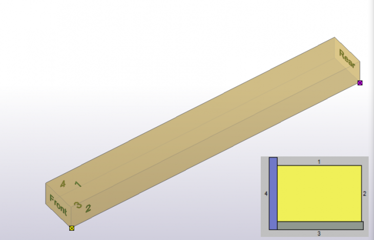
In Timber, initially all parts have a rectangular cross section and all parts are prismatic.
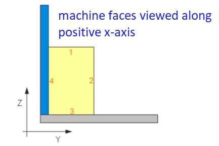
In total, initially, each part has 6 faces: four longitudinal and two end faces.
On the Hundegger machine, the longitudinal faces are numbered: 1,2,3,4 and the end faces are denoted as Front and Rear.
Next image illustrates this.
Image
In the appendices these numbers are used to define configurations.
2. Processes, type and tools
Some operations are Separating operations (S)
Some operations are Discrete (D)
Some operation can be either Separating or Discrete (S ; D)
Some operations are Profiling (P)
Some operations can be either Discrete or Profiling (D ; P)
Some operations that are Annotative (A)
Next table shows the list of current available operations (processes) and their type.
| Process | Volumetric/Planar | Type | Tool | Remark |
|---|---|---|---|---|
| Cut | Planar | S | - | |
| Double Cut | Volumetric | S | - | |
| Ridge Lap | Volumetric | S | j152 | Only spliced configurations |
| Slot | Volumetric | D | - | |
| Lap | Volumetric | D | j152 | Only spliced configurations |
| Birds Mouth | Volumetric | D | - | |
| Block House Half Lap | Volumetric | D | j152 | Only spliced configurations |
| Drilling | Volumetric | D | ||
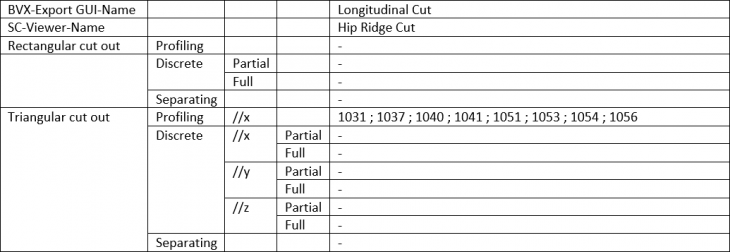
| Longitudinal Cut | Volumetric | D ; P | - | |
| Ridge Cut | Volumetric | D ; P | d153 | |
| Valley Cut | Volumetric | D ; P | d153 | |
| Brace Shoulder | Volumetric | S | j152 | Only spliced configurations |
| Rabbet | Volumetric | D ; P | - | |
| Groove | Volumetric | D ; P | - | |
| Marking | Volumetric | A | m116 | |
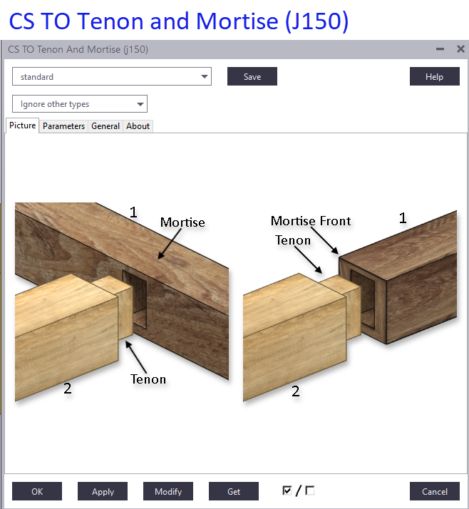
| Tenon | Volumetric | D ; S | j150 | |
| Mortise | Volumetric | D ; S | j150 | |
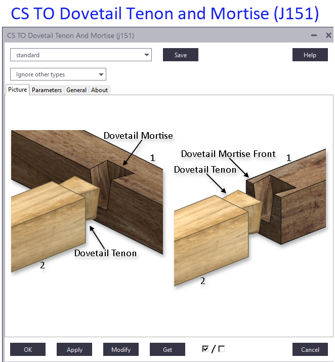
| Dovetail Tenon | Volumetric | D ; S | j151 | |
| Dovetail Mortise | Volumetric | D ; S | j151 |
Construsoft developed some tools. The table shows for which operations this is the case and which tool can be used to model them.
3. Planar operation - Cut
In BVX, a cut is a planar operation that separates a portion of a solid.
Modelling:
A Cut operation can be modelled using a either a Fit or a Trim command.
When there is only one saw cut at an end then it should be modelled using a Fit.
When there is more than one saw cut at one end then the first Cut should be a Fit and all subsequent others should be Trim.
Remark(s)
There is no parameter to control the distance over which the Cut operation stretches. Therefore, a cut will always start and end in thin air.
4. BVX volumetric operations have different scopes
In BVX, an operation is defined on a reference side (RS) and described by its:
- Position
- Orientation
- Geometry
Review the BVX File format description and the native BVX file viewer for details.
Each operation has its own scope with respect to:
- The faces on which it can be defined
- How many faces it can affect
- The shape of the removed solid
- Orientational parameters
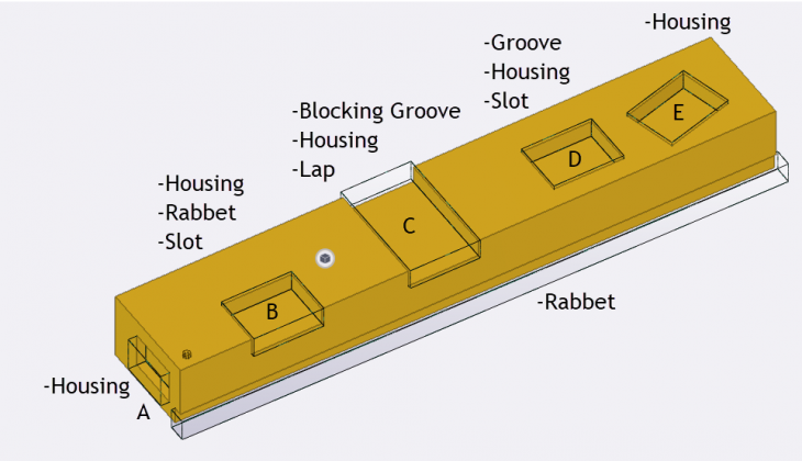
Because of scope and definition, there are cut outs that can be modelled with more than one BVX-operation. There are however also cut outs that only suit one specific BVX-operation.
Next image illustrates this:
Image

In general:
The dimensions of a rectangular block shape are unambiguously described by three independent parameters.
In space, the position of a volume is unambiguously described by three independent coordinates.
In space, the orientation of a volume is unambiguously described by three independent angles.
When one independent parameter is not present on an operation it means that the scope of that operation is limited because the “missing” parameter is calculated and, hence, is dependent.
Example1: Comparison between Housing and Lap in terms of dimensions:
A Housing has an independent parameter that controls the width
A Lap does not have an independent parameter that controls the width.
Image
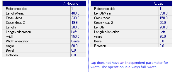
This is the reason why operation C can be described as both a Housing and a Lap and operation B cannot be described by a Lap.
Example2: Comparison between Housing and Slot in terms of orientation.
A Housing operation has an independent parameter to control the in-plane angle.
A Slot operation does not have an independent parameter to control the in-plane angle.
Image
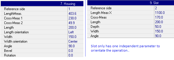
This is the reason why operation D can be described by both a Housing and a Slot and operation E cannot be described by a Slot.
Image
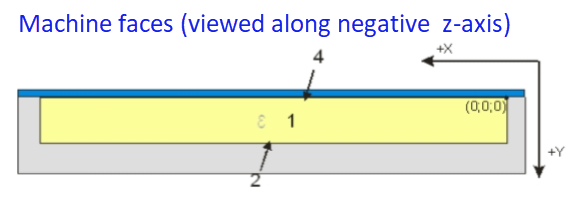
5. Machine faces
Next image shows the coordinate system on the machine.
Image
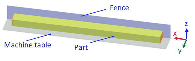
In BVX, an operation is described on one of the four longitudinal faces of the virginal solid. In BVX this face is denoted as reference side.
Image
Image
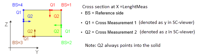
6. Reference side
An operation is defined on a Reference side.
Each reference side has its own local coordinate system in which the position of the operation is described.
Image
7. Positional and angular parameters
As mentioned, the position and orientation of a 3D-solid can be unambiguously described by 6 independent parameters, three for position and three for orientation.
The position is described by the values of LengthMeas, Q1 and Q2.
The angular parameters are the rotations about the axes of the local coordinate system of the applied reference side (LengthMeas-, Q1- and Q2-axis)
For operations that support more than one angular parameter, the order in which the angle values are applied must be maintained.
Review the BVX File format description and the native BVX file viewer for details per operation.
8. Shape of negative volume and shape of cut out
Each volumetric operation is to be modelled using a negative volume.
Note that the shape of the negative volume does not necessarily match the shape of the cutout:
Image
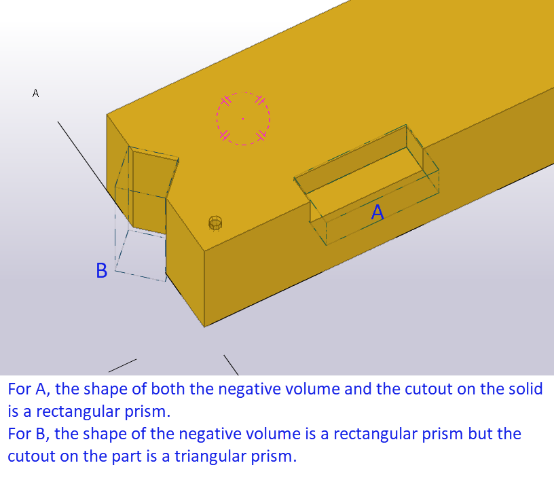
A rectangular, block shaped prismatic negative volume can affect either 1, 2, 3 or 4 faces of the virginal solid.
The actual shape of the portion of solid that is removed can vary as well. Most often this is either a
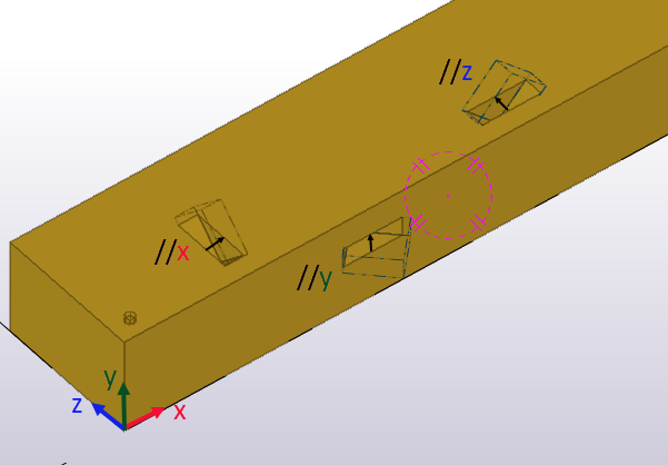
a. Rectangular prism. Here it does not matter whether the negative volume’s local x-axis is // to the parts local x-,y- or z-axis.
b. Triangular prism. Here it does matter whether the negative volume’s local x-axis is // to the parts local x-, y-, or z-axis.
Image

9. Configurations
In this document, no combination of operations is mentioned. The reason is that there are too many combinations possible. Looking at single operations and considering:
- Number of faces affected (1; 2; 3 or 4 faces) → 6 + 15 + 20 +15 = 56 permutations
- Shape of cutout (rectangular or triangular prism) → 2 permutations
- Direction of system axis of the negative volume that yield a triangular prism relative to the parts
UCS (//x ; //y ; //z) → 3 permutations.
So, in total: 56 + 3*56 = 224 configurations are considered. Each configuration is assigned a unique number.
Appendix A describes all possible configurations in which:
- The shape of the cutout on the solid is a single blockshaped rectangle.
- 1, 2, 3 or 4 faces are affected
- The orientation of the block is such that each side of it is // to one of the local axes of the part.
Appendix B describes all possible configurations in which:
- The shape of the cutout on the solid is a single right angled, trangular prism.
- 1, 2, 3, or 4 faces are affected
- The orientation of the triangular prism is such that its system line is // to either the local x-, y- or z-axis
of the part.
Note that some configurations cannot be modelled or make no sense. In the Appendices, these configurations are denoted in red.
10. Tekla tools
Some operations and combinations of operations are hard to model manually. For these, Construsoft developed dedicated tools. These tools will assign the appropriate names to the negative volumes.
Tenon- and mortise → J150
Dovetail tenon- and mortise → J151
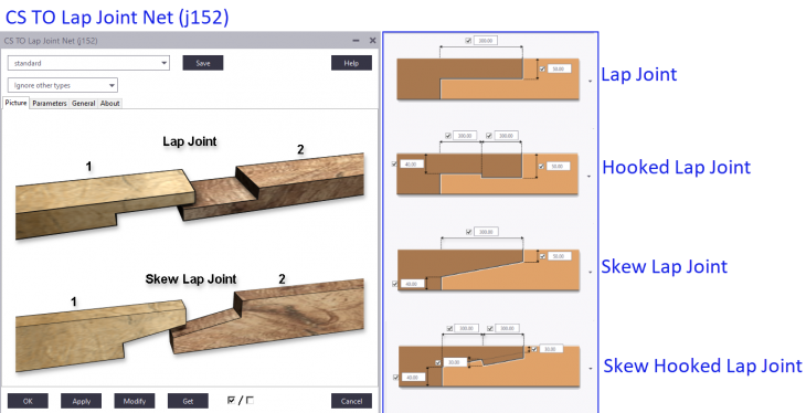
Lap Joints → J152
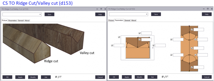
Ridge/Valley cut → d153
Image
Image
Image
Image
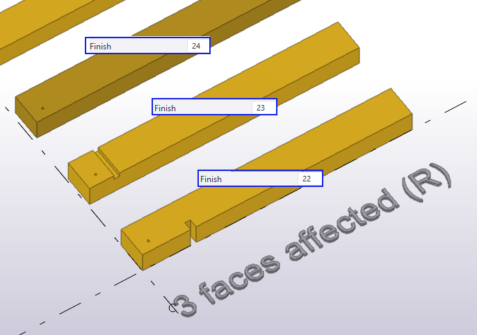
11. Tekla model
What follows can best be viewed in concurrence with the model: BVX-operations.
The model contains all configurations mentioned in both Appendix A and B.
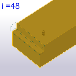
The configuration number is represented by the Finish attribute on the part.
Image
For each operation mentioned below, there is a filter.
The name of the filter is BVX_[Operation], e.g.: BVX_RABBET.
The filter only shows the configurations that can be exported to the operation mentioned in the filter name.
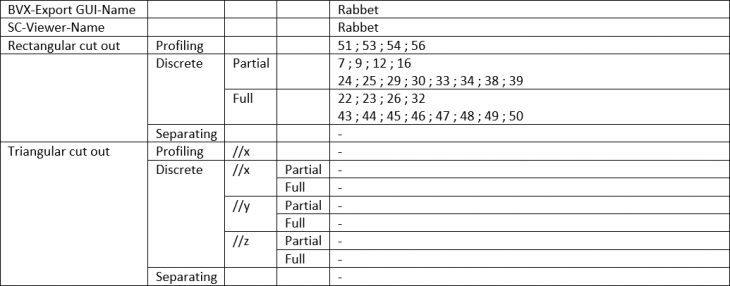
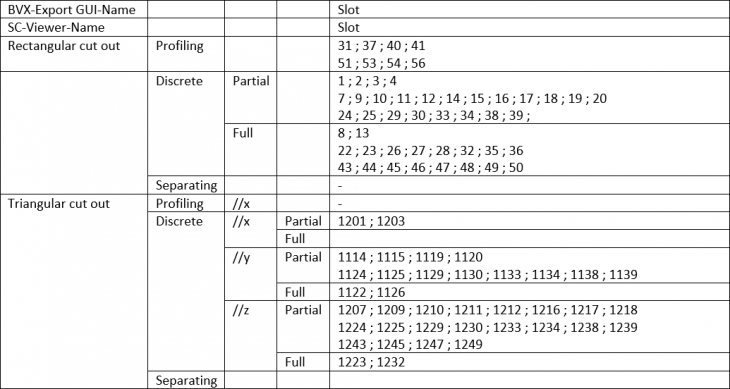
Scope per operation
The name of an operation is denoted in three environments:
- The GUI of the export tool
- The actual BVX file
- The SC-Viewer
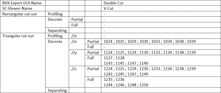
Unfortunately, the name of certain operations is not the same in these environments.
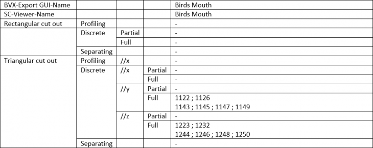
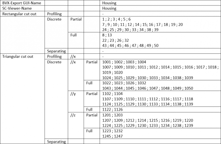
In next overview the table header is the denotation in the BVX file, the other two denotations are shown in the table.
Note: The tables indicate the theoretical scope of each operation. It does not take into account whether or not it is practical to apply a certain operation in that configuration.
12. Scope per operation that require rectangular or triangular prismatic cut out
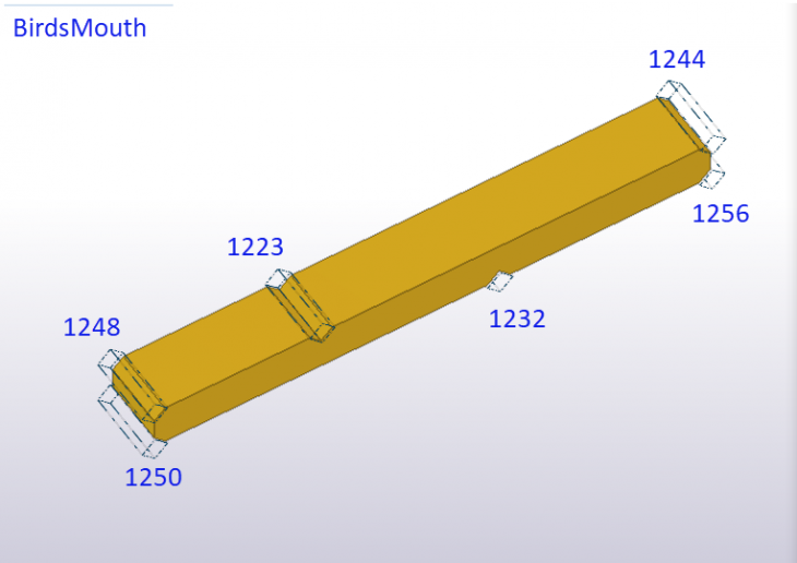
BirdsMouth
Image
Image
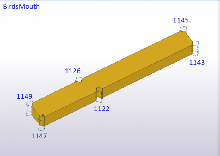
Image
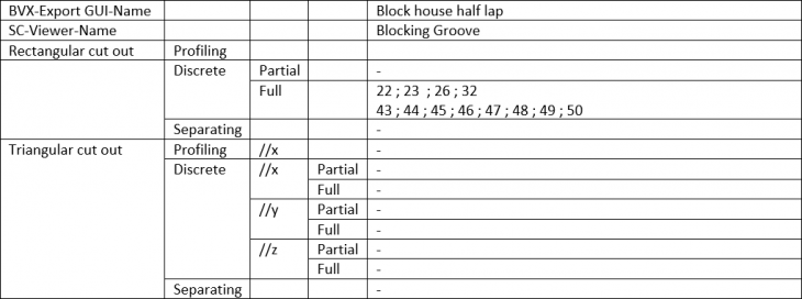
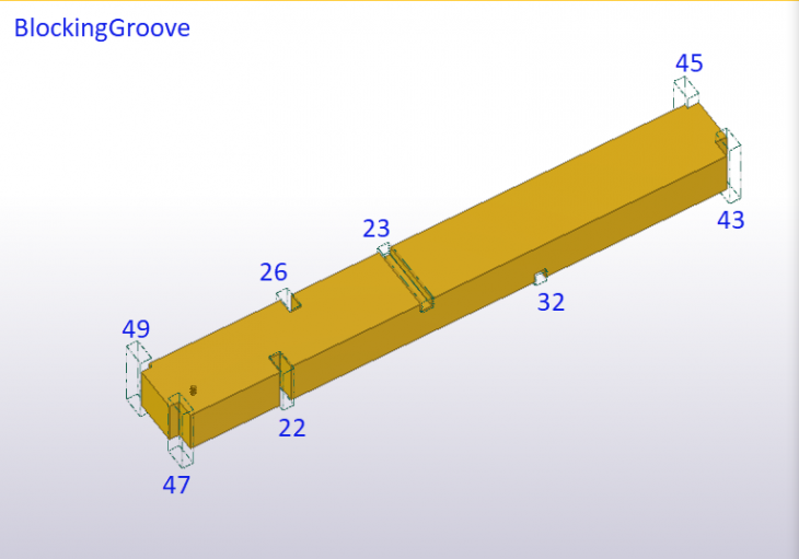
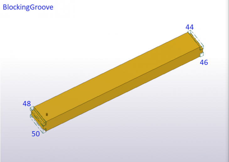
BlockingGroove
Image
Image
Image
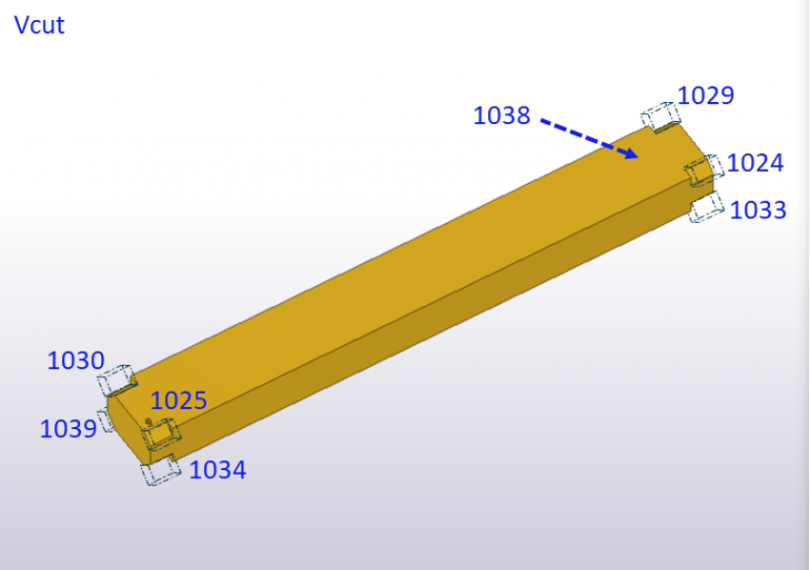
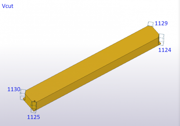
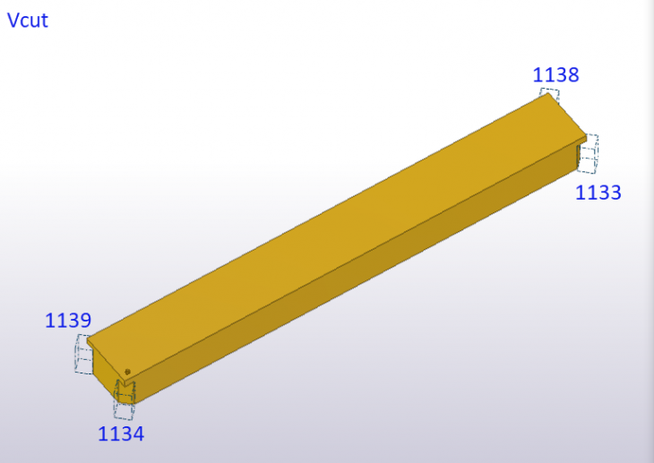
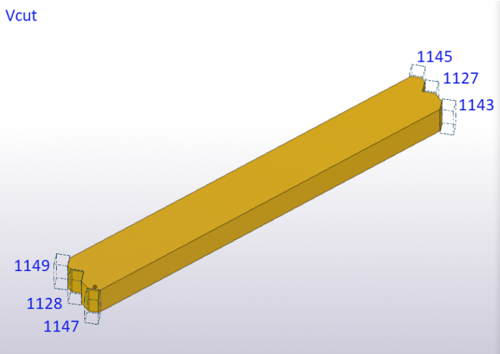
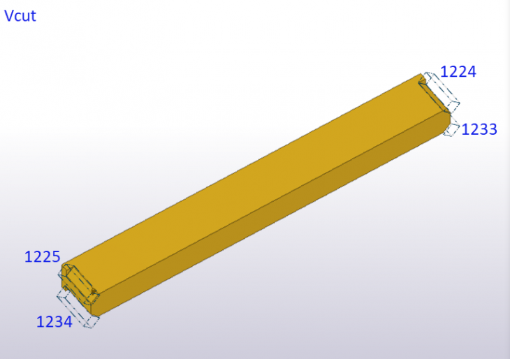
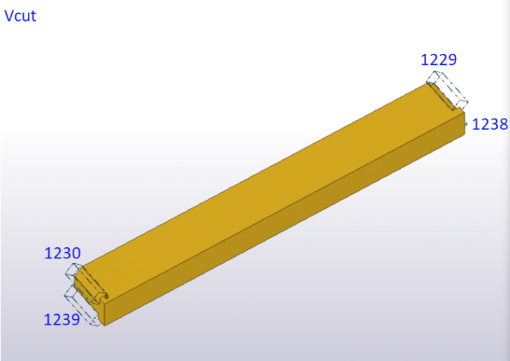
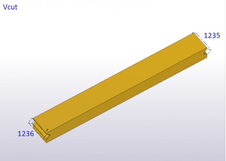
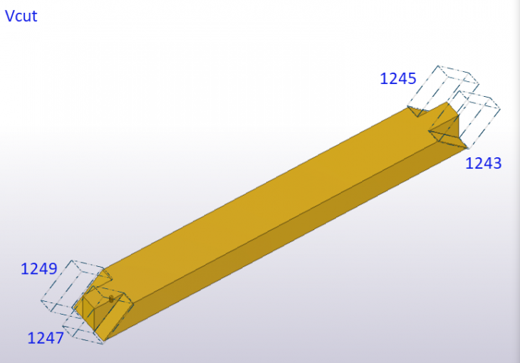
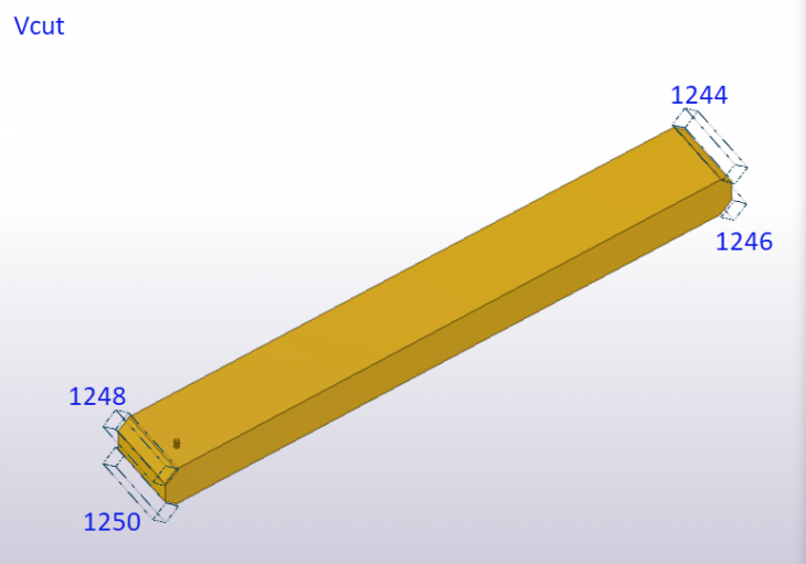
Vcut
Image
Image
Image
Image
Image
Image
Image
Image
Image
Image
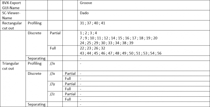
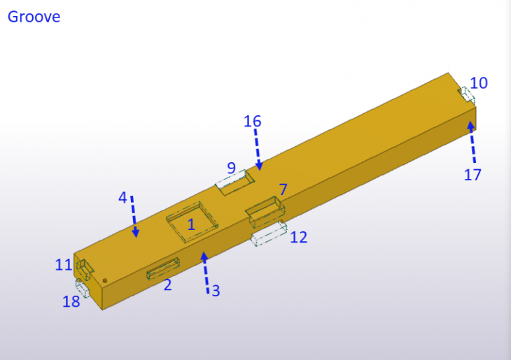
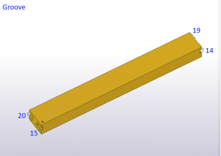
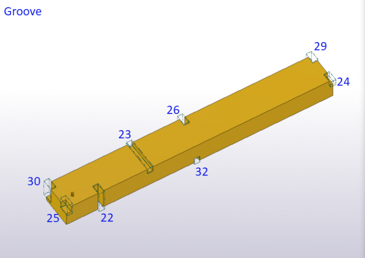
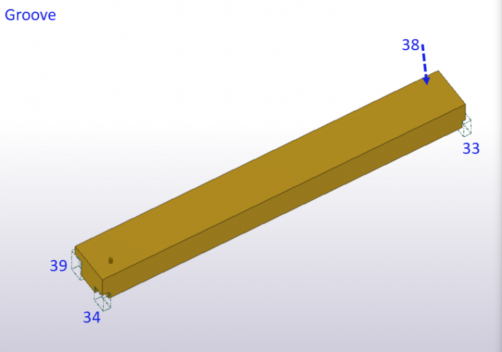
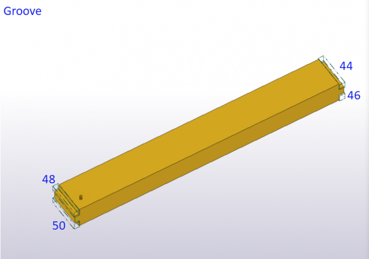
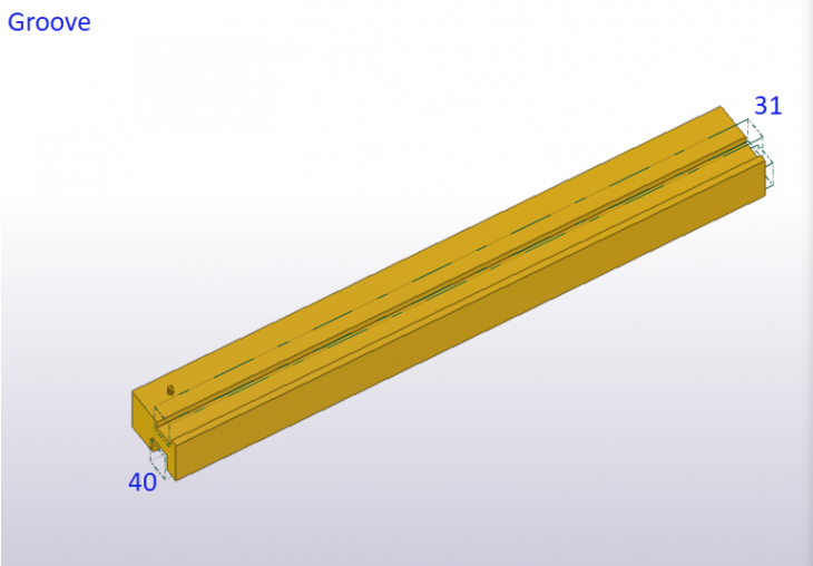
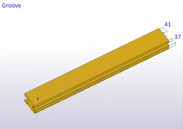
Groove
Image
Image
Image
Image
Image
Image

Image
Image
Image
Image

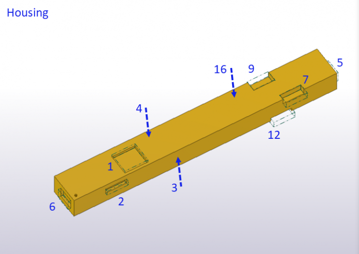
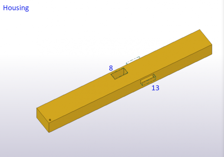
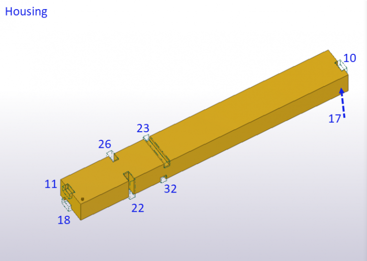
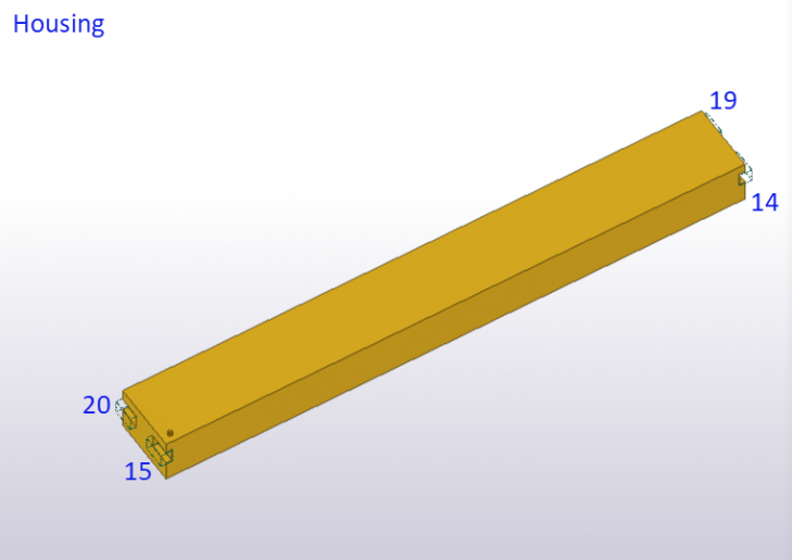
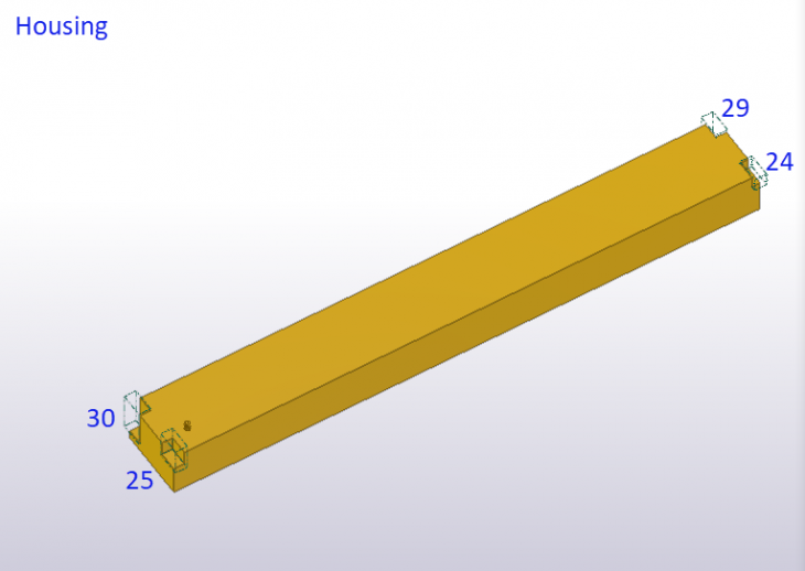
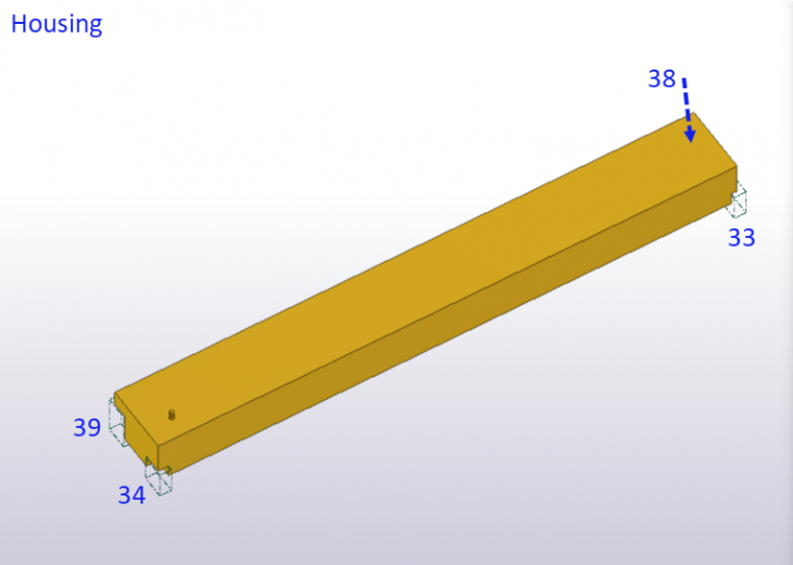
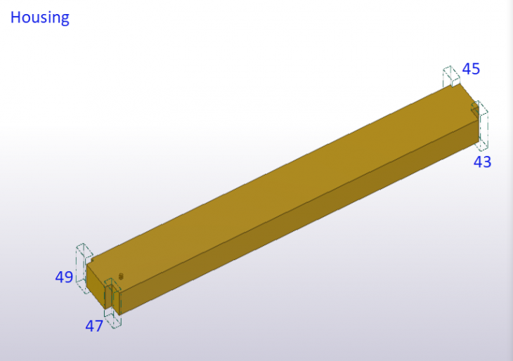
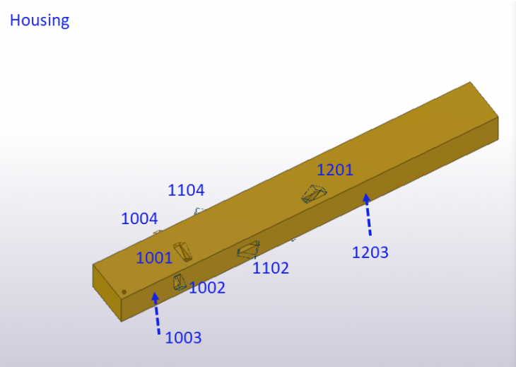
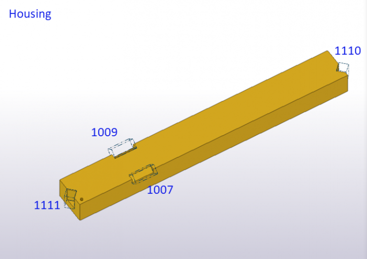
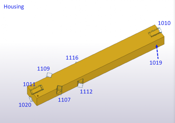
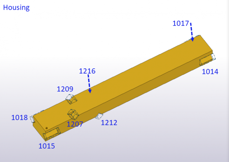
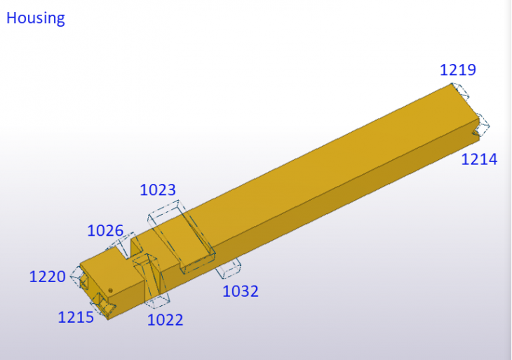
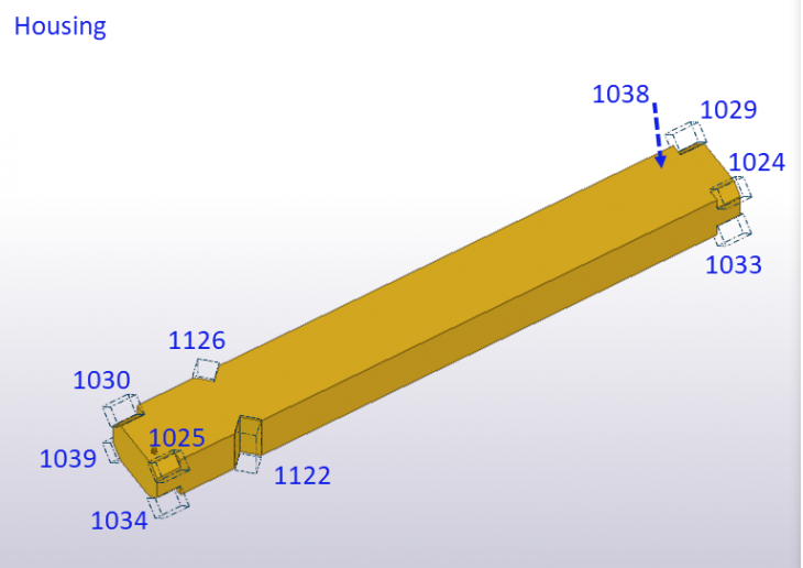
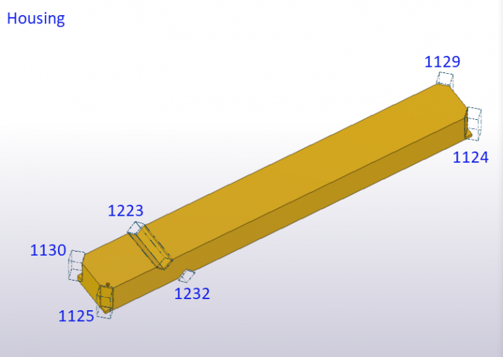
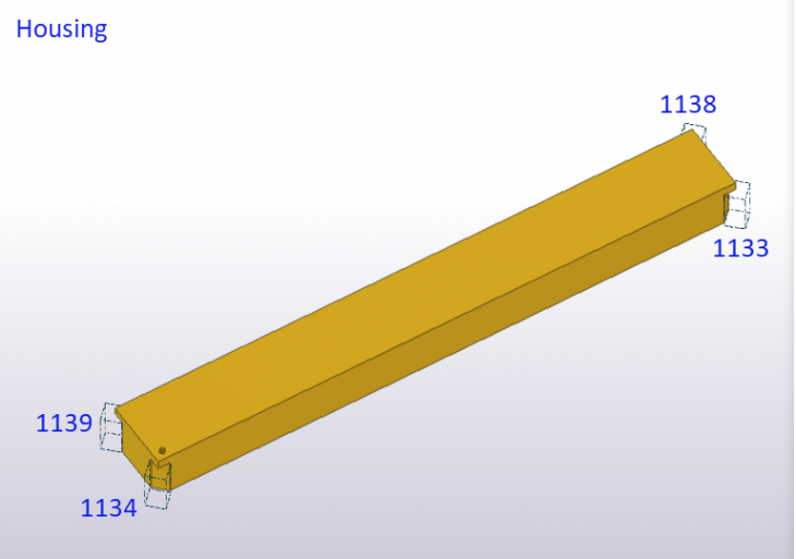
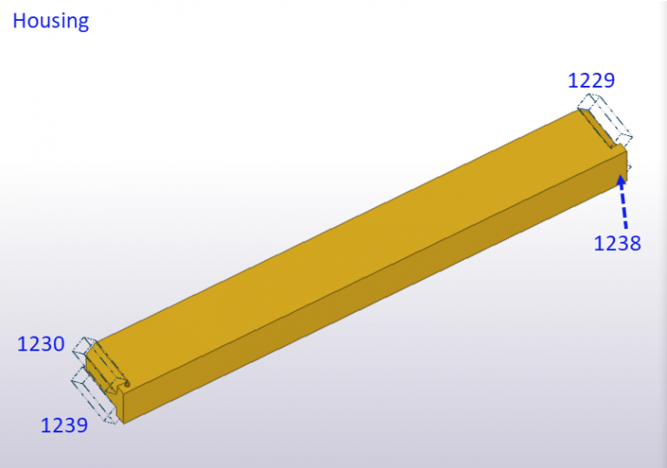
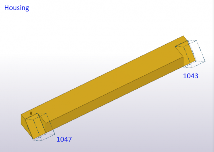
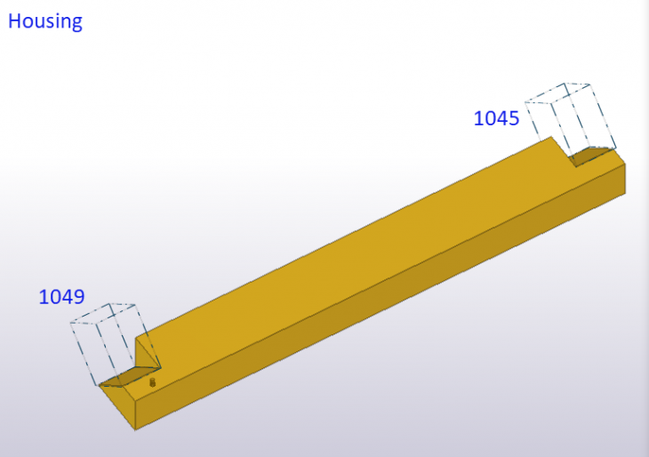
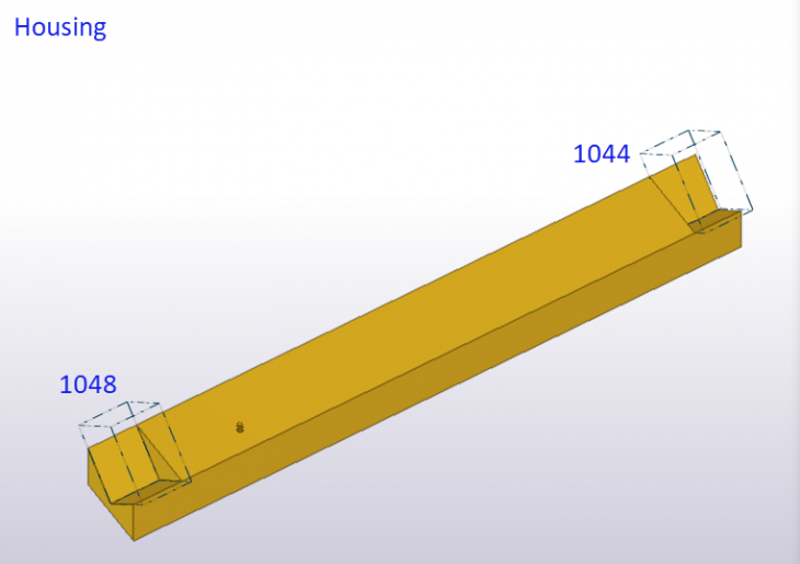
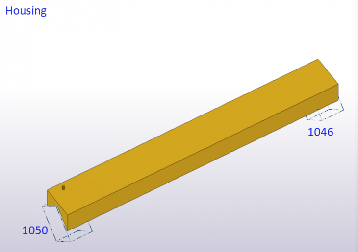
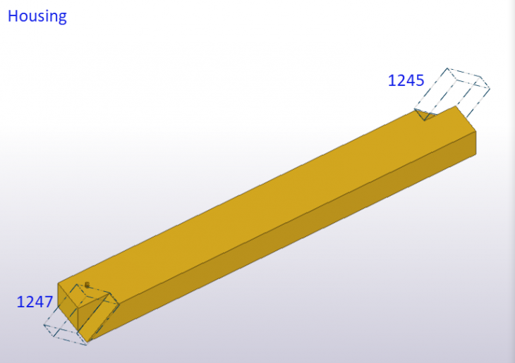
Housing
Image
Image
Image
Image
Image
Image
Image
Image
Image

Image
Image
Image

Image
Image
Image
Image
Image
Image
Image

Image
Image
Image
Image
Image
Image
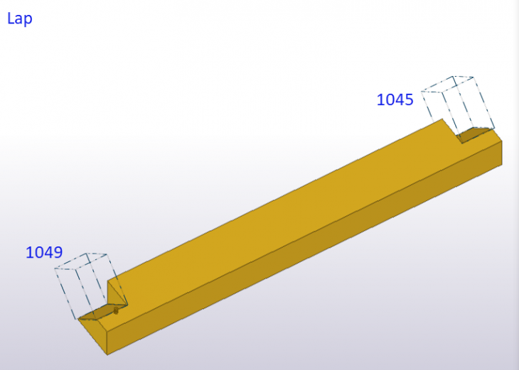
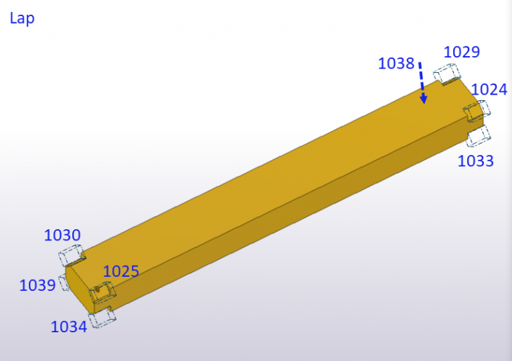
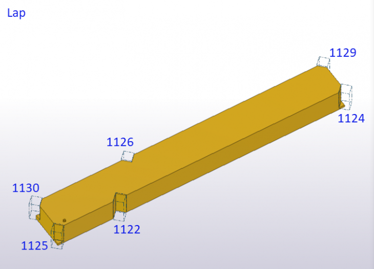
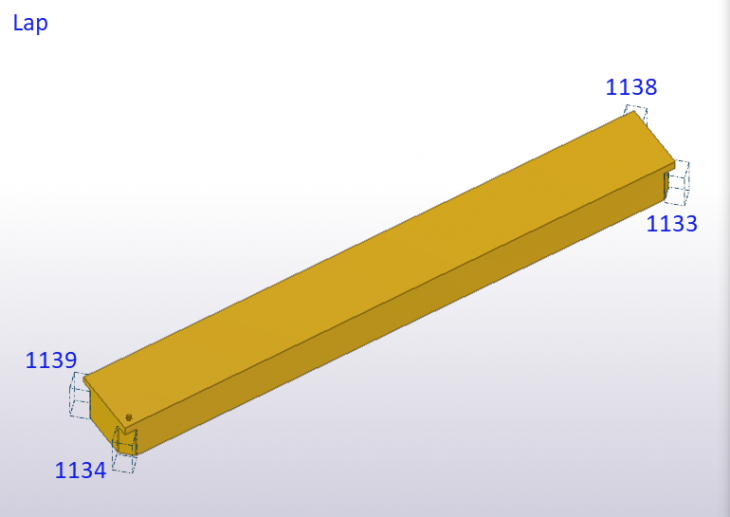
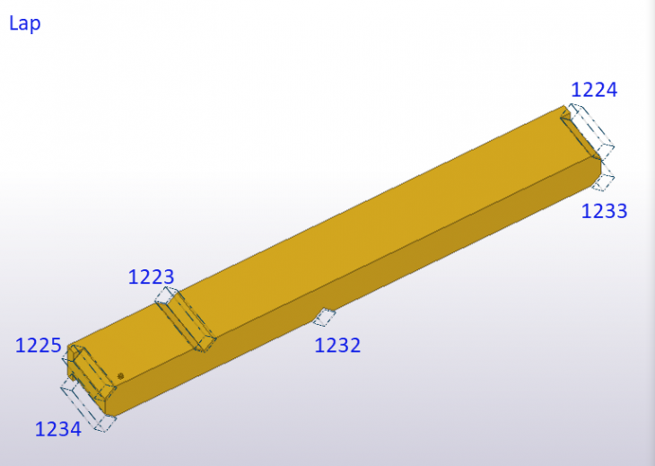
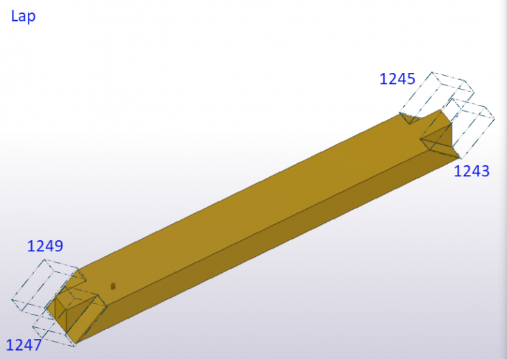
Lap
Image
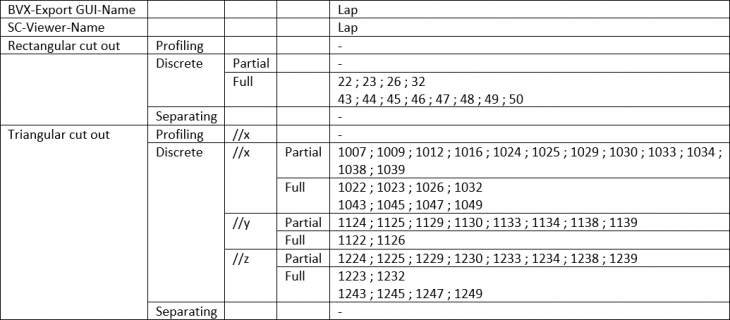
Image
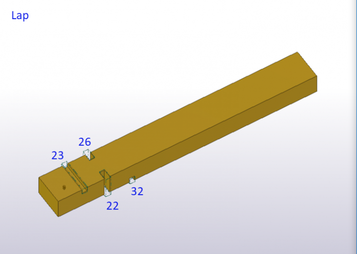
Image
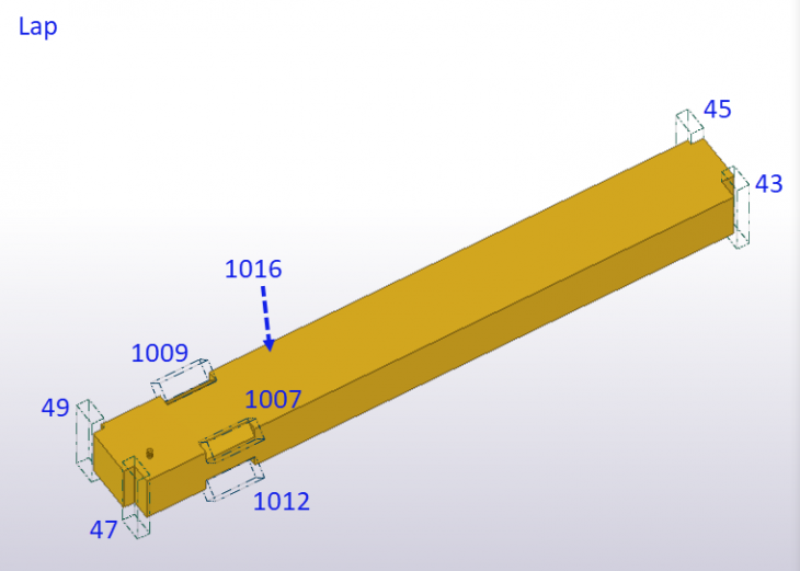
Image

Image
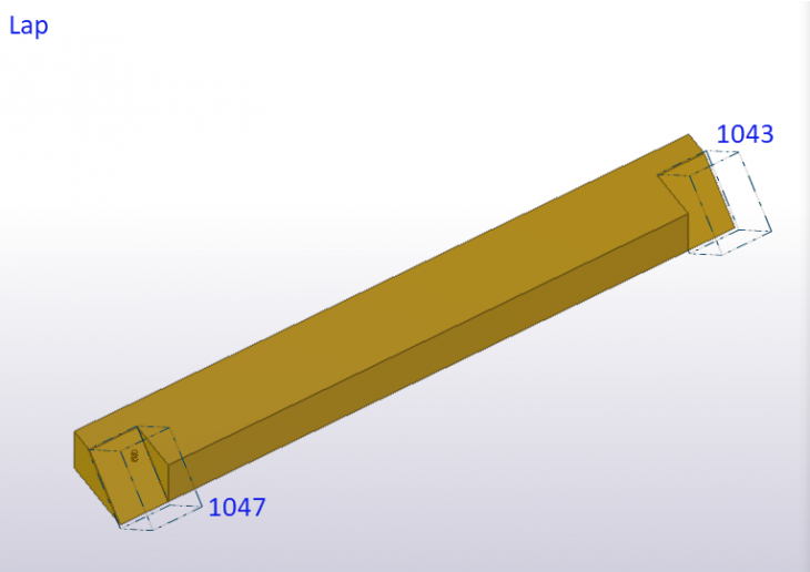
Image
Image
Image
Image
Image
Image

Image
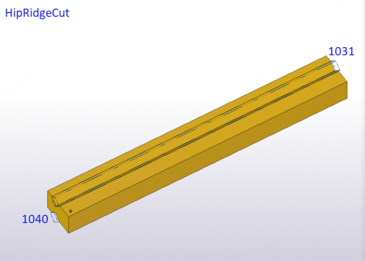
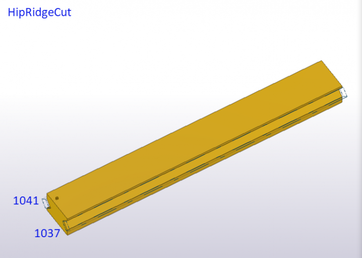
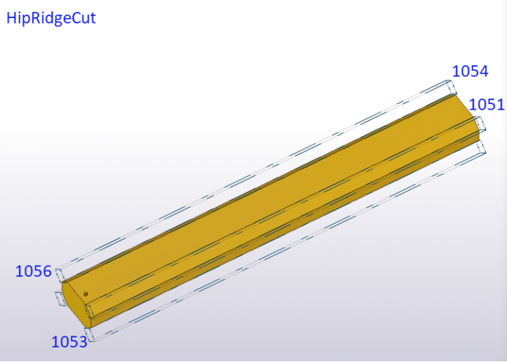
HipRidgeCut
Image
Image
Image
Image
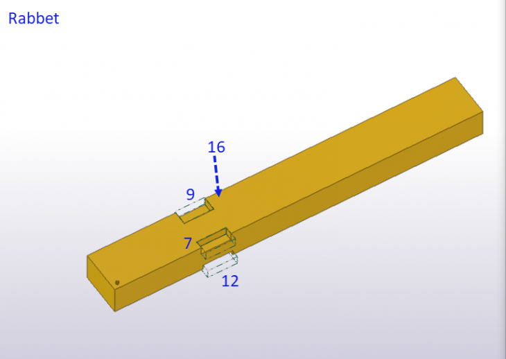
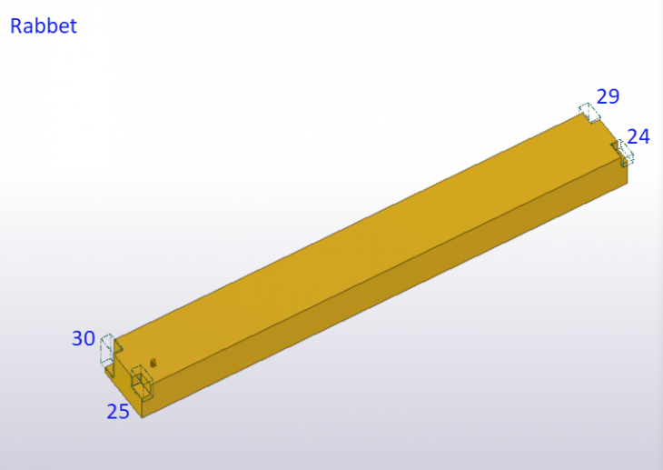
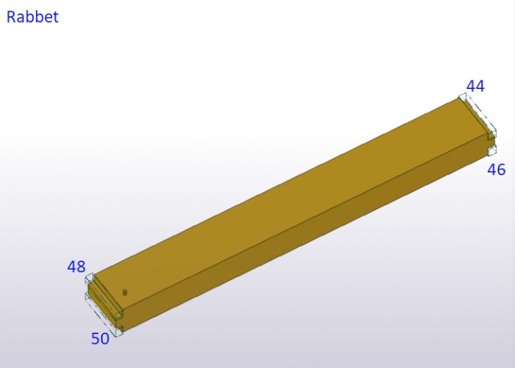
Rabbet
Image
Image
Image
Image

Image

Image
Image

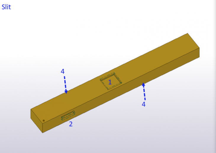
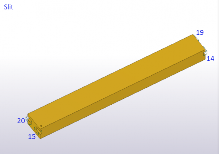
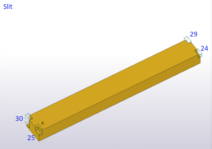
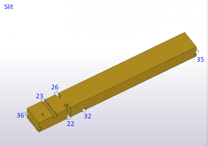
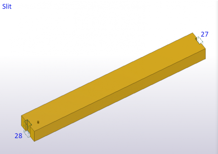
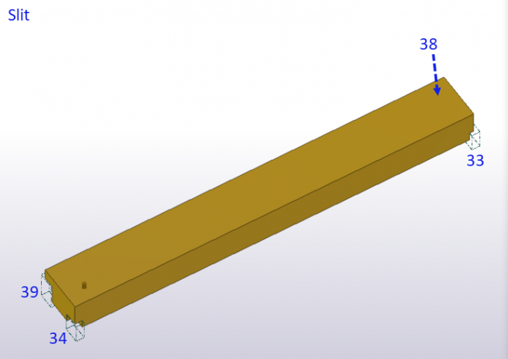
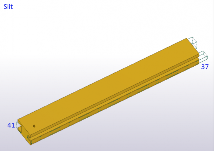
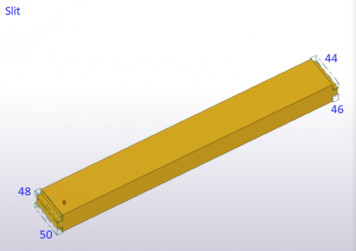
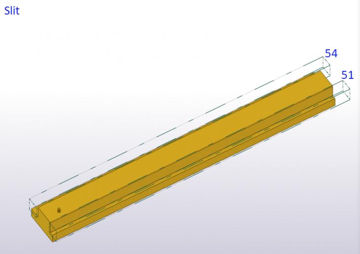
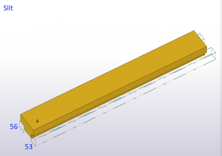
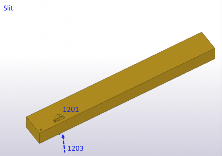
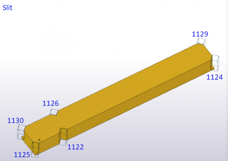
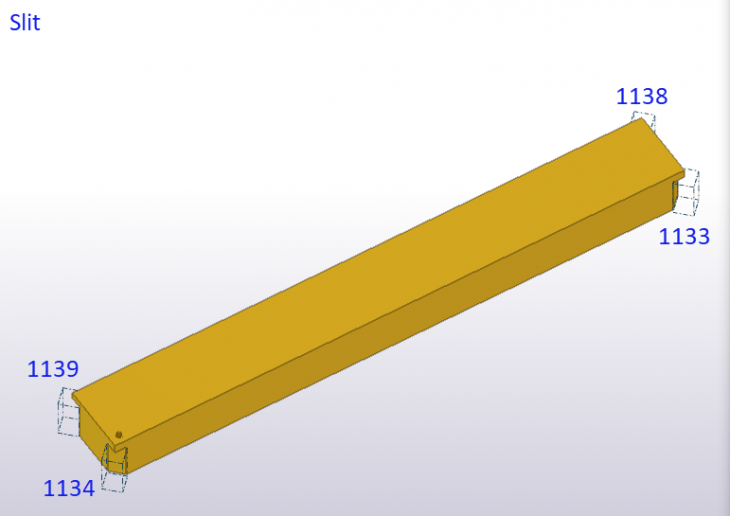
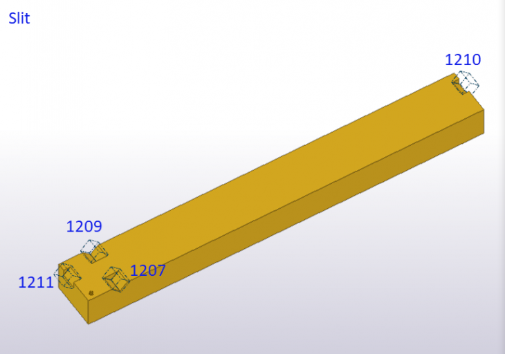
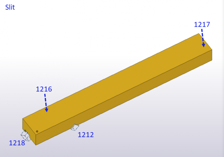
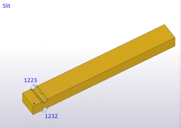
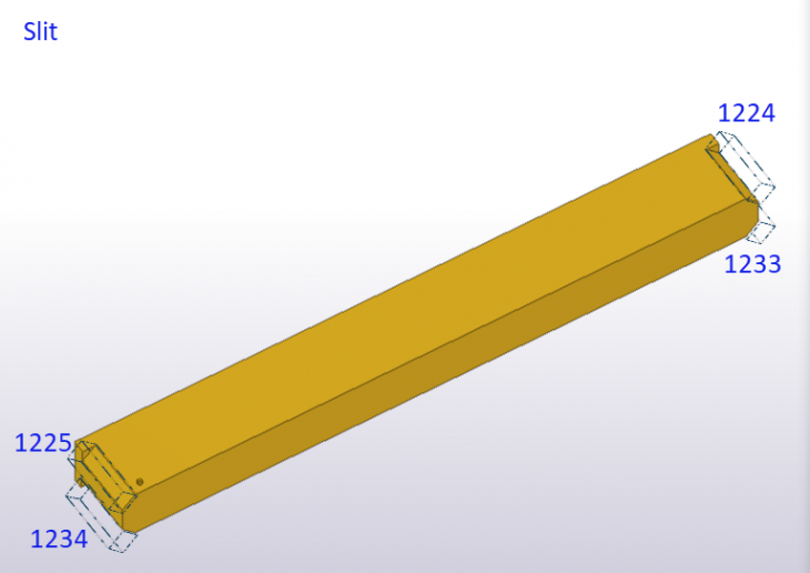
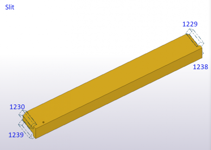
Slit
Image
Image
Image

Image
Image
Image
Image
Image
Image

Image
Image

Image
Image
Image
Image
Image

Image
Image
Image
Image
Image
Image
Image
Appendix A
This appendix contains all possible configurations for a single operation that cuts out a rectangular prism.
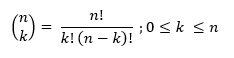
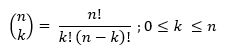
The number of permutations of k items out of a group of n items can be calculated with:
Let n be the number of faces on a virginal solid with a rectangular cross section. This means n = 6.
Let k be the number of faces that is affected by the operation. This means k ranges from 1 to 4.
The number of configurations that affect 1 face = 6
The number of configurations that affect 2 faces = 15
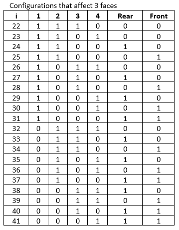
The number of configurations that affect 3 faces = 20
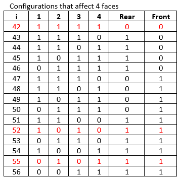
The number of configurations that affect 4 faces = 15
So, in total there are 56 permutations for configurations that cut out a rectangular prism.
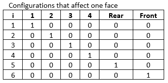
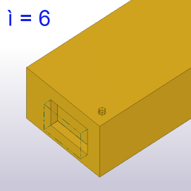
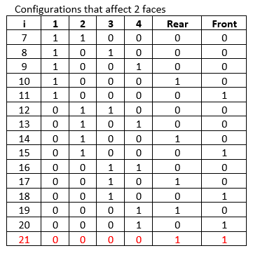
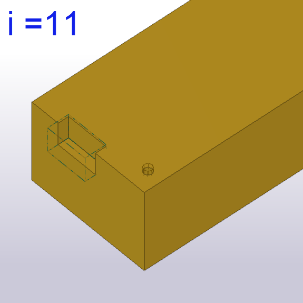
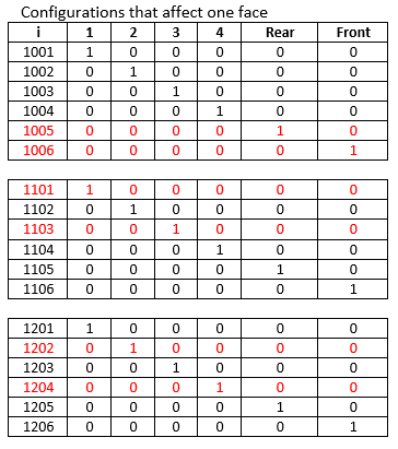
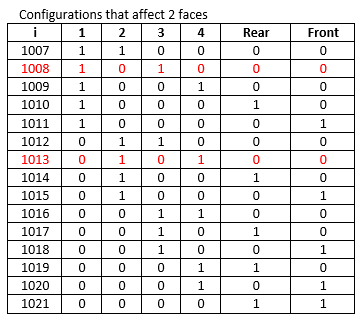
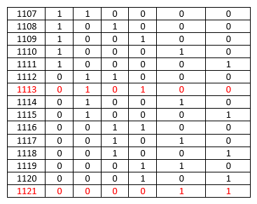
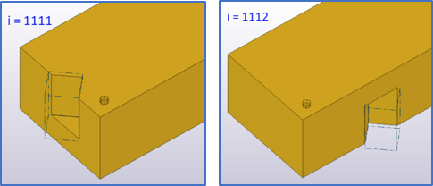
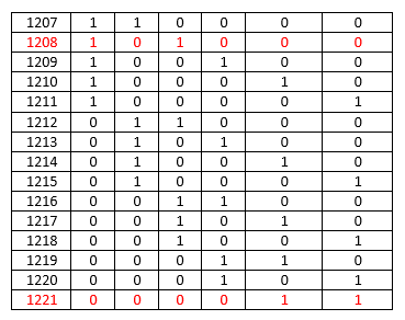
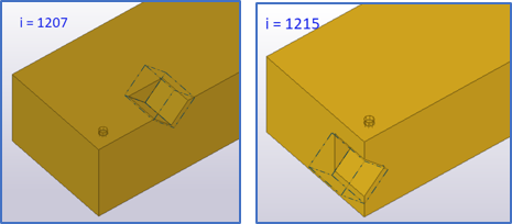
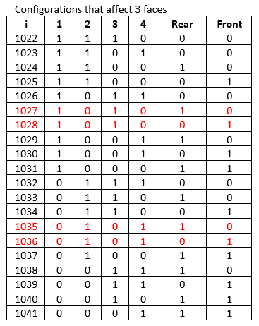
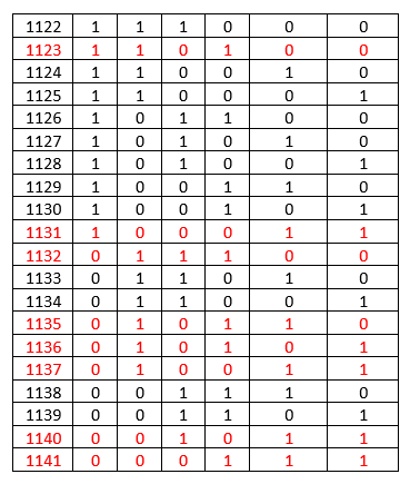
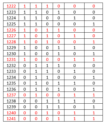
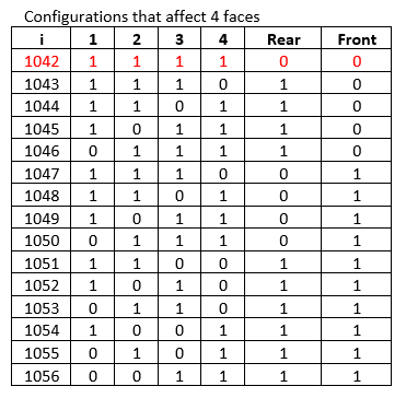
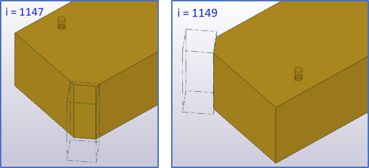
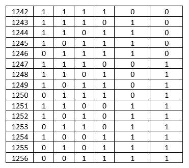
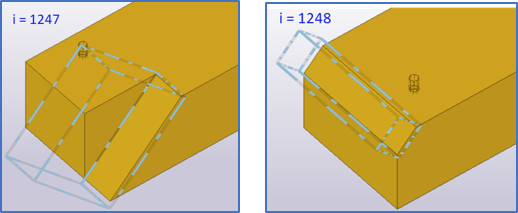
In next tables a record contains 7 fields:
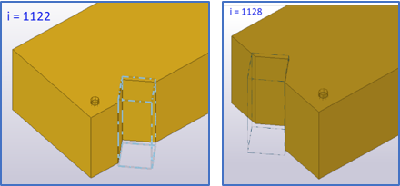
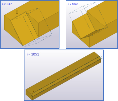
1st field denotes the unique number of the configuration
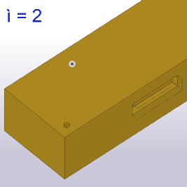
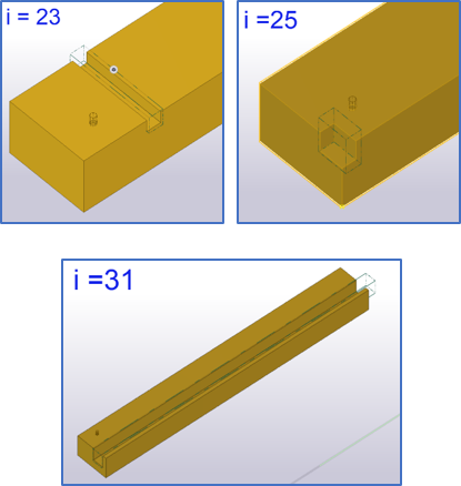
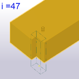
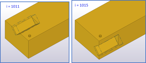
2nd ,3rd, .., 7th fields represent the faces on the solid. A value 1 means the face is affected, a value 0 means that the face is not affected. Next to a table some configurations are illustrated.
There are configurations that are impossible in Timber NC, these are denoted with red text.
The number of permutations of k items out of a group of n items can be calculated with:
Image
Let n be the number of faces on a virginal solid with a rectangular cross section. This means n = 6.
Let k be the number of faces that is affected by the operation. This means k ranges from 1 to 4.
The number of configurations that affect 1 face = 6
The number of configurations that affect 2 faces = 15
The number of configurations that affect 3 faces = 20
The number of configurations that affect 4 faces = 15
So, in total there are 56 permutations for configurations that cut out a rectangular prism.
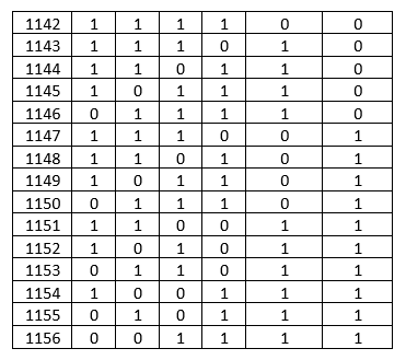
In next tables a record contains 7 fields:
1st field denotes the unique number of the configuration
2nd ,3rd, .., 7th fields represent the faces on the solid. A value 1 means the face is affected, a value 0 means that the face is not affected. Next to a table some configurations are illustrated.
There are configurations that are impossible in Timber NC, these are denoted with red text.
Image
Image
Image
Image
Image
Image
Image
Image
Image
Image
Image
Appendix B
This appendix contains all possible configurations for a single operation that cuts out a right-angled triangular prism.
The number of permutations of k items out of a group of n items can be calculated with:
Let n be the number of faces on a virginal solid with a rectangular cross section. This means n = 6.
Let k be the number of faces that is affected by the operation. This means k ranges from 1 to 4.
The number of configurations that affect 1 face = 6
The number of configurations that affect 2 faces = 15
The number of configurations that affect 3 faces = 20
The number of configurations that affect 4 faces = 15
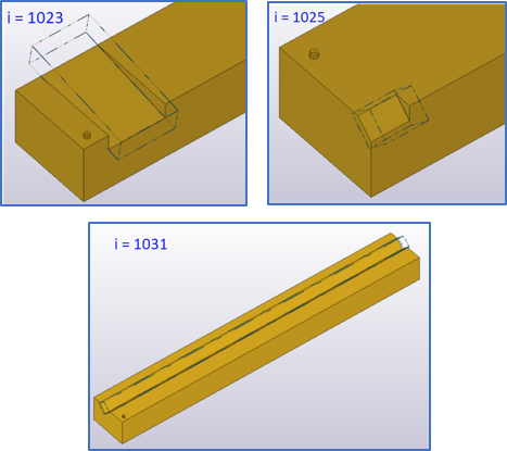
For a triangular prism there is a need to vary the system line:
So, in total there are 3 times 56 = 168 permutations for configurations that cut out a triangular portion.
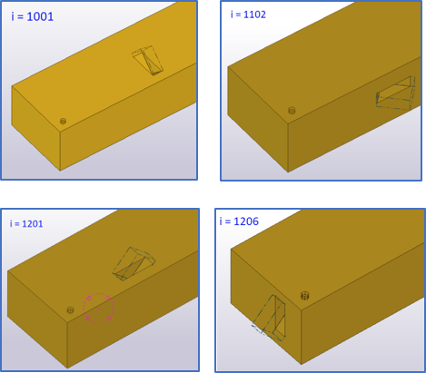
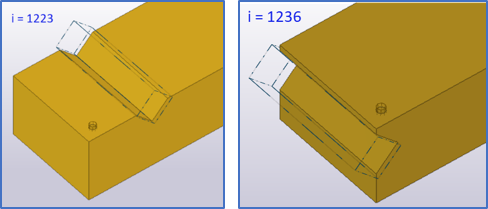
The configurations that describe a triangular cut out in the solid, start with number 1001
For configurations //x the number ranges from 1001 to 1056
For configurations //y the number ranges from 1101 to 1156
For configurations //z the number ranges from 1201 to 1256
There are configurations that are impossible in Timber NC, these are denoted with red text.
The number of permutations of k items out of a group of n items can be calculated with:
Image
Let n be the number of faces on a virginal solid with a rectangular cross section. This means n = 6.
Let k be the number of faces that is affected by the operation. This means k ranges from 1 to 4.
The number of configurations that affect 1 face = 6
The number of configurations that affect 2 faces = 15
The number of configurations that affect 3 faces = 20
The number of configurations that affect 4 faces = 15
For a triangular prism there is a need to vary the system line:
Image
So, in total there are 3 times 56 = 168 permutations for configurations that cut out a triangular portion.
The configurations that describe a triangular cut out in the solid, start with number 1001
For configurations //x the number ranges from 1001 to 1056
For configurations //y the number ranges from 1101 to 1156
For configurations //z the number ranges from 1201 to 1256
There are configurations that are impossible in Timber NC, these are denoted with red text.
Image
Image
Image
Image
Image
Image
Image
Image
Image
Image
Image
Image
Image
Image
Image
Image
Image
Image
Image
Image
See also