Provided performance P354 floor vibration
System frequency
Deflections
For the primary beam, the base maximum simply supported deflection, δPBSS, is derived from the analysis model with no allowance for boundary conditions.
For the secondary beam, the base maximum simply supported deflection, δSBSS, is derived from the analysis model and the maximum deflection for a fixed end condition, δSBFE, is calculated from,
| δSBFE | = | m*b*LSB4 /(384*ES *ISB ) + m*b*LSB2 /(24*G*Ay ) |
| Where | ||
| m | = | unit mass in kN/mm2 |
| b | = | secondary beam spacing in mm |
| LSB | = | span of the secondary beam in mm |
| ISB | = | the inertia of the secondary beam in mm 4 |
| ES | = | the steel modulus in kN/mm2 |
| G | = | the steel shear modulus in kN/mm2 |
| Ay | = | the major axis shear area in mm2 |
For the slab, the base maximum deflection for a fixed end condition, δSlabFE, is calculated from,
| δSlabFE | = | m*LSlab 4/(384*EC *ISlab) |
| Where | ||
| m | = | unit mass in kN/mm 2 |
| LSlab | = | span of the slab in mm |
| ISlab | = | the inertia of the slab in mm 4/mm |
| EC | = | the dynamic concrete slab modulus in kN/mm2 |
| = | Es *1.1/αshort |
These base, maximum simply supported deflections for both primary and secondary beams, δ **SS, derived from the analysis model, can be adjusted to cater for boundary conditions for 'two-span continuous' or 'three-span continuous' cases to give δ barSS.
For 'two span continuous' the adjusted deflection is taken from P354 as,
| δbarSS | = | MIN[(0.4 + kM /kS * (1 + 0.6 * LS 2/LM2 ))/(1 + kM /kS ), 1.0] * δ**SS |
| Where | ||
| kM | = | the 'stiffness' of the critical span selected by the user (primary or secondary beam as appropriate) |
| = | IM /LM | |
| kS | = | the stiffness of the adjoining span selected by the user (primary or secondary beam as appropriate) |
| = | IS/LS | |
| LM | = | the span of the critical span selected by the user (primary or secondary beam as appropriate) |
| LS | = | the span pf the adjoining span selected by the user (primary or secondary beam as appropriate) |
| IM | = | the inertia of the critical span selected by the user (primary or secondary beam as appropriate) |
| IS | = | the inertia of the adjoining span selected by the user (primary or secondary beam as appropriate) |
For 'three span continuous' the adjusted deflection is taken from P354 as,
| δbarSS | = | MIN[(0.6 + 2 * kM /k S * (1 + 1.2 * LS2 /LM2 ))/(3 + 2 * kM /k S ), 1.0] * δ**SS |
| Where | ||
| kM | = | the 'stiffness' of the critical (middle) span selected by the user (primary or secondary beam as appropriate) |
| = | IM /LM | |
| kS | = | the stiffness of the adjoining (outer) span selected by the user (primary or secondary beams as appropriate) |
| = | IS /LS | |
| LM | = | the span of the critical (middle) span selected by the user (primary or secondary beam as appropriate) |
| LS | = | the span of the adjoining (outer) span selected by the user (primary or secondary beams as appropriate) |
| IM | = | the inertia of the critical (middle) span selected by the user (primary or secondary beam as appropriate) |
| IS | = | the inertia of the adjoining (outer) span selected by the user (primary or secondary beams as appropriate) |
Secondary Beam Mode
In this mode the primary beams form nodal lines (zero deflection) about which the secondary beams vibrate. The slab is assumed to be continuous over the secondary beams so a fixed end condition is used.
| δSBmode | = | δ barSBSS + δ SlabFE |
| and | ||
| fSBmode | = | 18/ √ δ SBmode |
Primary Beam Mode
In this mode the primary beams vibrate about the columns as simply supported beams whilst the secondary beams and slabs are taken to be fixed ended
| δPBmode | = | δbarPBSS + δSBFE + δSlabFE |
| and | ||
| fPBmode | = | 18/ √ δPBmode |
System Frequency
The natural frequency of the system, f0, is calculated from,
| f0 | = | MIN{ fSBmode , fPBmode } |
Limitations
The absolute minimum natural frequency of the floor system is limited to 3.0 Hz. Where the floor system frequency is below these limits the design fails.
Similarly, no single element within the floor structure should have a fundamental frequency less than 3.0 Hz. Three additional checks are therefore carried out and their results only published if there is a Fail. These checks are,
| fPBSS =18/ √ δ PBSS must be ≥ 3 else the design Fails |
| fSBSS =18/ √ δ SBSS must be ≥ 3 else the design Fails |
| fSlabFE =18/ √ δSlabFE must be ≥ 3 else the design Fails |
Modal mass
The 'modal mass' is the effective mass participating in the vibration of the floor. In accordance with SCI P354, it is taken as the 'unit mass' multiplied by the effective plan area of the floor participating in the motion as given by,
| M | = | m * Leff * S |
| Where | ||
| m | = | the unit mass in kg/m2 |
| Leff | = | the effective floor length |
| S | = | the effective floor width |
| Where | ||
| Leff | = | 09*(1.10)ny-1 *(E*ISB/(m*b*f02))0.25 but ≤ ny*Ly |
| Where | ||
| ny | = | number of bays ( ≤ 4) in the direction of the secondary beam span |
| EISB | = | dynamic flexural rigidity of the composite secondary beam (in Nm2 when m is in kg/m2) |
| b | = | floor beam spacing (in m) |
| f0 | = | system, natural frequency from above |
| Ly | = | span of the secondary beam (in m) |
| and | ||
| S | = | η*(1.15)nx-1 *( E*ISlab /(m* f02 ))0.25 but ≤ nx *Lx |
| Where | ||
| nx | = | number of bays ( ≤ 4) in the direction of the primary beam span |
| EISlab | = | dynamic flexural rigidity of the slab (in Nm2 when m is in kg/m2 ) system, |
| f0 | = | natural frequency from above |
| Lx | = | span of the primary beam (in m) |
| Where | |||
| η | = | frequency factor | |
| = | 0.5 | for f0 < 5 Hz | |
| = | 21*f0 - 0.55 | for 5 Hz ≤ f0 ≤ 6 Hz | |
| = | 0.71 | for f0 > 6 Hz |
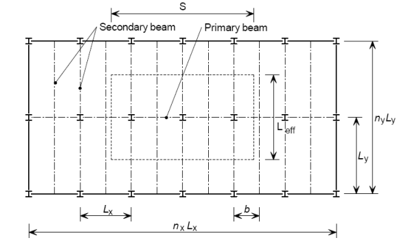
Figure 1: Definition of variables used to establish effective modal mass
Mode Shape Factor
As previously described, there are two main mode shapes which relate to the lowest frequencies - a secondary beam mode and a primary beam mode. The lowest frequency of the two modes is used and the mode shape factors is determined using the same mode.
There are two mode shape factors, μe at the point of excitation and μr at the point of response.
If the response and excitation points are unknown, or if a general response for the whole floor is required, μe and μr can conservatively be taken as 1.
Tekla Structural Designer will not calculate the values of these mode shape factors, and will default to 1.0 but also gives you the option of providing values to be used.
Resonance Build-up Factor
The 'resonance build-up factor' makes an allowance for the time it takes for someone walking across the floor to begin to excite the floor - vibration is not instantaneous upon the first footfall. Hence, a 'walking time' is required and is calculated from the 'walking distance' (see:Maximum corridor length) divided by the 'walking velocity'.
First it is necessary to calculate the walking velocity as given by Equation 16 of SCI P354,
| V | = | 67*fp2 - 4.83*fp + 4.5 | for fp in the range 1.7 to 2.4 Hz |
| Where | ||
| fp | = | the pace (walking) frequency supplied by the user |
The resonance build-up factor is taken from Equation 37 of SCI P354,
| ρ | = | 1 - e (-2*π*ζ Lp*fp /V) |
| Where | ||
| ζ | = | the damping ratio |
| Lp | = | the walking distance |
| V | = | the walking velocity given above |
Note that the resonance build-up factor has an upper bound of 1.0 and may, conservatively be set to 1.0.
Resonance Acceleration
Low Frequency Floors
For system frequencies between 3 Hz and 10 Hz, the root mean square (rms) acceleration is calculated from,
| aw,rms | = | μe* μr* 0.1*Q*W*ρ/(2 * √2*M * ζ) |
Where
| μe & μr | = | mode shape factors | |
| Q | = | the person's weight taken as 745.6 N (76 kg) | |
| M | = | the modal mass (kg) | |
| = | the damping ratio | ||
| ρ | = | the resonance build-up factor | |
| W | = | the appropriate code-defined weighting factor for the human perception of vibrations, based on the fundamental frequency, f 0 | |
| = | f0 /5 | for 2 ≤ f0 < 5 | |
| = | 1.0 | for 5 ≤ f0 ≤ 16 | |
| = | 16/f0 | for f0 > 16 | |
High Frequency Floors
For system frequencies greater than 10 Hz, the root mean square (rms) acceleration is calculated from the following expression, which assumes that the floor exhibits a transient response,
| aw,rms | = | 2*π* μ e* μ r * 185*Q*W /(M*f00.3*700* √2) |
Response Factor
The 'base curves' in BS 6472: 1992 are given in terms of root mean square (rms) acceleration
The provided response factor is then calculated from,
| Rprov | = | a w,rms /0.005 |
The 'required response factor', Rreqd, is a user input and leads to the final design condition,
| Rprov | ≤ | R reqd |
In SCI P354 the recommended Response Factors derive from BS 6472: 1992, where they are called 'Multiplying Factors' and are reproduced in SCI P354 as Tables 5.2 and 5.3.
Vibration Dose Values
When the floor has a higher than acceptable response factor, the acceptability of the floor may be assessed by considering the intermittent nature of the dynamic forces. This is accomplished by carrying out a Vibration Dose Value [VDV] analysis.
This method calculates the number of times an activity (for example walking along a corridor) will take place during an exposure period, na, from,
| na | = | (1/Ta )*(VDV/(0.68*a w,rms ))4 |
| where | ||
| Ta | = | the duration of the activity |
| = | L p/V if L p is known OR | |
| = | value supplied by user if L p is not known | |
| VDV | = | VDV value supplied by user, (default 0.4). |
Typical VDV values are shown below:
| Vibration dose limits (m/s1.75) for z-axis vibration specified by BS 6472 | |||
|---|---|---|---|
| Place | Low probability of adverse comment | Adverse comment possible | Adverse comment probable |
| buildings 16 h day | 0.2 to 0.4 | 0.4 to 0.8 | 0.8 to 1.6 |
| buildings 8 h night | 0.13 | 0.26 | 0.51 |