Grasshopper-Tekla Live Link
Not version-specific
Tekla Structures
Environment
Not environment-specific
Image

- Download the link from Tekla Warehouse.
- See the Grasshopper-Tekla Link FAQ for answers to common issues.
- To run a Grasshopper definition directly from Tekla Structures, check out the Grasshopper Component.
- You can control drawings from Grasshopper by using the open-source Grasshopper-Tekla Drawing Link (download the package on the right-hand side under "Releases").
Introduction
The Grasshopper-Tekla live link enables algorithmic modelling for Tekla Structures using Rhino/Grasshopper. The link is a set of Grasshopper components that can create and interact with objects live in Tekla Structures.
Back to topDemo Videos
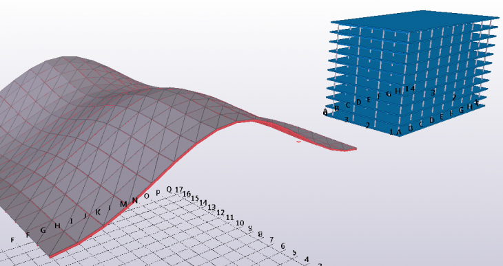
Building Frame
Double-Curved Roof
Concrete Bridge Deck Part 1
Concrete Bridge Deck Part 2
Prerequisites
You need to have Rhino (download) and Tekla Structures installed on the same machine.
- For Rhino 8, you need to make Rhino 8 use the .Net Framework - use the SetDotNetRuntime command in Rhino and set it to NETFramework, then restart Rhino.
You can try out the full version of Rhino for free for 90 days.
Back to topSetup
-
Download the Grasshopper-Tekla link installation zip package from Tekla Warehouse.
-
Make sure you download a package targeting the (installed) Tekla Structures version you'd like to work with
-
-
Extract GrasshopperTeklaLink.gha and GrasshopperTeklaLink.Setup.exe into any location on the disk.
-
Run GrasshopperTeklaLink.Setup.exe and allow admin rights if asked for.
-
This will unblock the .gha and replace any old link version.
-
Rhino and Grasshopper should be closed during the install.
-
-
Launch Tekla Structures and create a new model.
-
Launch Rhino and Grasshopper. A new component tab labeled Tekla [version] should appear, as well as a menu labeled Tekla in the menu bar.
-
If using Rhino 8, type the SetDotNetRuntime command in Rhino and set it to NETFramework, then restart Rhino. This needs to be done only once.
-
-
Open the TeklaGrasshopperLinkExample.gh file in Grasshopper.
- The solution should run and generate some example objects in the Tekla model
-
If some objects aren’t showing up, you probably need to expand the work area and/or view depth
Image
Note that any components in existing definition (including any already inserted ones) will always interact with whatever Tekla version the currently installed .gha targets.
Manual installation
Check the Installation Instructions.txt document in the zip package in case you need to install the link manually without using the Setup.exe.
Back to topFrequently Asked Questions
See the Grasshopper-Tekla Link FAQ for answers to common issues.
Back to top
The Grasshopper Components
After installation, the components are visible on the Tekla component tab in Grasshopper.
Image
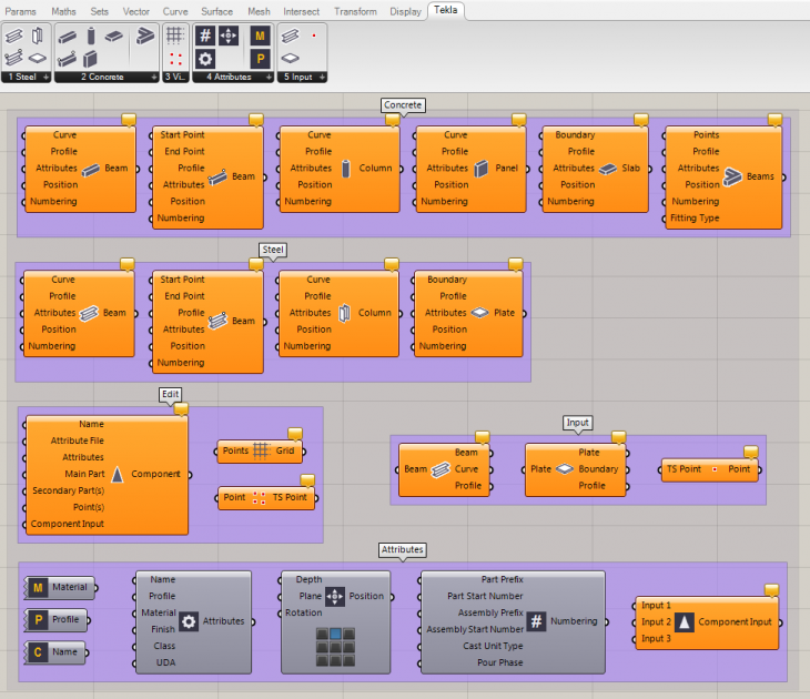
Additionally there's a Tekla menu added to the Grasshopper top menu bar, with commands to enable/disable all Tekla components, recompute all Tekla components, delete Tekla objects etc. as well as a commands for setting the default Tekla attributes (like profiles) that are applied to generated objects.
Important general notes about the components
-
Make sure you have a Tekla model open before opening Grasshopper or inserting any component. The components generate, modify and interact with objects live in Tekla Structures.
-
The link uses the units of the currently open Rhino Document for the geometrical inputs.
-
Select a component in Grasshopper to highlight the associated objects in Tekla Structures.
-
Double-click the icon of a component to re-run the component manually. This operation also re-generates any deleted members in Tekla Structures.
-
If you right-click an (object creating) component icon, there’s an option called Run in background which is set to true by default. This mode means the Tekla model is updated in the background while the Grasshopper UI remains responsive. When a solution is run in this mode, components that are currently processing objects in Tekla are marked with a spinner and the objets they generate will become available at the component outputs once they are ready.
-
To cut the link between a Grasshopper component and the Tekla objects it has generated, right-click the component and select Bake to Tekla. This will leave the object as-is in Tekla, and a copy of the object will be generated upon further modifications of the component input.
Param Components
These components can be used to reference Tekla objects into Grasshopper.
-
Tekla PointImage

Pick a point in Tekla Structures to be used in Grasshopper. The picked point will be visible in Tekla as well as a construction point. -
Tekla LineImage

Pick a line in Tekla Structures to be used in Grasshopper. The picked line will be visible in Tekla as well, as a construction line. -
Tekla PolylineImage

Pick a polyline in Tekla Structures to be used in Grasshopper. The picked polyline will be visible in Tekla as well, as a construction polycurve. -
Tekla FaceImage

Pick a face of an object in Tekla Structures to be used in Grasshopper. The picked face will be visible in Tekla as well, as a construction polycurve. You can inquire the object the face belongs to with the 'Get Father' component.
-
BeamImage

Reference a beam from Tekla into Grasshopper. -
PlateImage

Reference a plate from Tekla into Grasshopper. -
ItemImage

Reference an item from Tekla into Grasshopper. -
ReinforcementImage

Reference reinforcement from Tekla into Grasshopper. -
ComponentImage

Reference a component from Tekla into Grasshopper. -
Model ObjectImage

Reference any model object from Tekla into Grasshopper.
-
Construction PointImage

Reference a construction point from Tekla into Grasshopper. -
Construction LineImage

Reference a construction line from Tekla into Grasshopper. -
Construction Arc (Tekla Structures 2019 or newer)Image

Reference a construction arc from Tekla into Grasshopper. -
Construction CircleImage

Reference a construction circle from Tekla into Grasshopper. -
Construction Polycurve (Tekla Structures 2019 or newer)Image

Reference a construction polycurve from Tekla into Grasshopper. -
Construction PlaneImage

Reference a construction plane from Tekla into Grasshopper.
Right-click the above param components to open the context menu, where you find commands to set one or multiple objects or points in Tekla Structures. Grasshopper will be minimized and Tekla Structures will ask you to pick objects.
If the objects that are connected to a component have been moved in the model, you can double-click the component to update the state of the object in Grasshopper. The component will also update its output anytime Rhino/Grasshopper is restarted.
The components remember the set input between Grasshopper sessions.
For the construction object params, the referenced geometry will automatically be converted into corresponding Rhino geometry when plugged into other Grasshopper components. So e.g. a referenced Tekla Arc becomes a Rhino Arc in Grasshopper. Most other referenced object types can be analyzed with the 'Deconstruct' components, and the solid geometry can be transferred into Grasshopper with the 'Convert to Brep' and 'Convert to Mesh' components.
-
Get Object By GuidImage

This component can be used to read in Tekla objects into the definition based on their GUIDS. -
Object PipelineImage

This component can automatically reference objects from the Tekla model based on their type and/or a selection filter.- The Auto Value List component can be used to get a dropdown of all the available types or selection filters.
Steel Components
-
BeamImage

Creates a steel beam along the provided curve or line. Right-click the component to set the maximum number of control points that will be used if a polybeam is created. 99 points is default. More points means greater accuracy but slower perfomance when updating. -
Beam 2PtImage

Creates a steel beam using the provided start and end point. -
ColumnImage

Creates a steel column along the provided line. If the input is not a straight line in the Z direction, the resulting Tekla object is a beam. -
PlateImage

Creates a steel plate outlined by the provided geometry. The boundary can be a point list, a simple surface, a rectangle, a circle, a polyline or a general curve. Right-click the component to set the maximum number of control points that will be used. 99 points is default. More points means greater accuracy but slower perfomance when updating. -
Bent Plate (Tekla Structures 2017 or newer)Image

Creates a bent plate outlined by the provided list of boundaries and with the provided radius(es). The input needs to be a minimum of two boundaries to connect. -
Lofted Plate (Tekla Structures 2019i or newer)Image

Creates a lofted plate between the two input curves
Note that the position can't be set for lofted plates in Tekla Structures (yet), thus the position input has no effect.
The created lofted plates can be invalid for some input curves. This is a Tekla core limitation, i.e. you would get the same result if you create them manually from similar polycurves in Tekla Structures. -
Item (Tekla Structures 2017 SP5, 2017i SP1 or newer)Image

Creates a steel item based on the provided brep, mesh or surface geometry. Alternatively you can specify a profile (shape) that will be inserted to the Tekla model. The optional Line input can be used to specify the origin and direction of the item.
When creating a Tekla item from a Rhino brep, the brep is meshed/triangulated internally by Rhino prior to being transfered. If you right-click the component icon/name, you can set the meshing parameters to Minimal, Coarse or Smooth. Default is Coarse. Minimal means faster model updates wherease Smooth means finer details but slower updates. If you're having trouble creating Items from Rhino breps or meshes, please see the FAQ. Note that brep/mesh conversion works better if you use Rhino 6.
If you right-click the component icon/name, there's an option "Show internal lines in Tekla" which can be used to show the mesh of the item in Tekla. -
AssemblyImage

Creates an assembly from the provided input parts/objects.
The Main Part input is optional, if left empty the main part will be the first part in the Objects input. Note that adding a part directly as the main part might make the assembly invalid e.g. if the part has connections.
Parts will be added as sub-assemblies, except for the optional main part. To create single-level steel assemblies, use the Cast Unit component instead.
Back to top
Concrete Components
-
BeamImage

Creates a concrete beam along the provided curve or line. Right-click the component to set the maximum number of control points that will be used if a polybeam is created. 99 points is default. More points means greater accuracy but slower performance when updating. -
Beam 2PtImage

Creates a concrete beam using the provided start and end point. -
ColumnImage

Creates a concrete column along the provided line. If the input is not a straight line in the Z direction, the resulting Tekla object is a beam. -
PanelImage

Creates a concrete panel along the provided curve or line. -
SlabImage

Creates a concrete slab outlined by the provided geometry. The boundary can be a point list, a simple surface, a rectangle, a circle, a polyline or a general curve. Right-click the component to set the maximum number of control points that will be used. 99 points is default. More points means greater accuracy but slower performance when updating. -
Lofted Slab (Tekla Structures 2019i or newer)Image

Creates a lofted concrete slab between the two input curves
Note that the position can't be set for lofted slabs in Tekla Structures (yet), thus the position input has no effect.
The created lofted slabs can be invalid for some input curves. This is a Tekla core limitation, i.e. you would get the same result if you create them manually from similar polycurves in Tekla Structures. -
Pad FootingImage

Creates a concrete pad footing along the provided curve or line. -
Strip FootingImage

Creates a concrete strip footing along the provided curve or line. -
Item (Tekla Structures 2017 SP5, 2017i SP1 or newer)Image

Creates a concrete item based on the provided brep, mesh or surface geometry. Alternatively you can specify a profile (shape) that will be inserted to the Tekla model. The optional Line input can be used to specify the origin and direction of the item.
When creating a Tekla item from a Rhino brep, the brep is meshed/triangulated internally by Rhino prior to being transferred. If you right-click the component icon/name, you can set the meshing parameters to Minimal, Coarse or Smooth. Default is Coarse. Minimal means faster model updates whereas Smooth means finer details but slower updates. If you're having trouble creating Items from Rhino breps or meshes, please see the FAQ. Note that brep/mesh conversion works better if you use Rhino 6.If you right-click the component icon/name, there's an option "Show internal lines in Tekla" which can be used to show the mesh of the item in Tekla.
-
Extrude BeamsImage

Creates beams between the points in the provided point list, so that the end point of one beam is the start point of the next one. Fittings are automatically applied between each beam pair. If the start and end points are the same, a fitting will be added there as well.
-
In addition to the geometrical inputs, each part creating component above has the following optional inputs:
-
Profile: The part profile as a string. You can use the Profile Catalog component to select a profile from the Tekla Profile catalog.
-
Attributes: The part attributes. Use the Part Attributes component to construct the input object.
-
Position: The part position. Use the Position component to construct the input object, or use the syntax
PLANE_ENUM(PLANE_OFFSET), ROTATION_ENUM(ROTATION_OFFSET), DEPTH_ENUM(DEPTH_OFFSET)
Syntax example: RIGHT(1200), TOP(45.0), BEHIND. See more examples by hovering the Position input.
-
Numbering: The part numbering attributes. Use the Numbering component to construct the input object.
-
Deforming (available for Beam type objects): The deforming and end offset attributes. Use the Deforming component to construct the input object.
-
-
RebarImage

Creates a single bar.
This component has a right-click option "Remove while inputs are being modified". This mode means the inserted bars in Tekla are removed while part and point inputs are being modified, to allow for quicker updates of the model. Note: In this mode, the bars will get new GUIDs after each input modification.-
Part: The Tekla part to reinforce.
-
Shape: The shape of the bar.
-
Attributes: The rebar attributes. Use the Rebar Attributes component to construct the input object. Alternatively you can connect the Reinforcement Catalog component to this input directly, or even provide just a size as a string or a number.
-
Hook: The hook attributes for the bar. Use the Hook component to construct the input object, or alternatively the Hooks component if you want to use different hooks for the bar ends.
-
Cover: The cover thicknesses and offsets for the bar. Use the Cover component to construct the input object.
-
-
Rebar GroupImage

Creates a bar group in a part.-
Part: The tekla part to reinforce.
-
Shape: The shape of the bars.
-
To create a tapered bar group, remove the grafting from the shape input and provide multiple shapes as a (non-grafted) list.
-
To create a curved bar group, the shape input should be a single arc (to create several curved groups, provide a grafted list of arcs).
-
To create a circular bar group, the shape input should be a single circle (to create several circular groups, provide a grafted list of circles).
-
-
Range: The range of the bar group. Normally the input is a line.
-
If the shape input is a list of shapes (forming a tapered group), you don't need to have a range input.
-
If the range input is a circle or arc, and the shape input is a single curve (or the shape input is grafted), the rebar group type will be tapered curved.
-
If the range input is a curve, and the shape input is a single curve (or the shape input is grafted), the shape curve will be copied along the range and the group type will be tapered.
-
-
Attributes: The rebar attributes. Use the Rebar Attributes component to construct the input object. Alternatively, you can connect the Reinforcement Catalog component directly to this input, or even provide just the size as a string or a number.
-
Hook: The hook attributes for the bar. Use the Hook Attributes component to construct the input object, or alternatively the Hooks Attributes component if you want to use different hooks for the bar ends.
-
Cover: The cover thicknesses and offsets for the bar. Use the Cover Attributes component to construct the input object.
-
Group: The group type (e.g. spiral), spacing and exclude type attributes. Use the Group Attributes component to construct the input object.
-
-
Cast UnitImage

Creates a cast unit from the provided input parts/objects.
The Main Part input is optional, if left empty the main part will be the first part in the Objects input. Note that adding a part directly as the main part might make the cast unit invalid e.g. if the part has connections.
This component can be used to create single-level steel assemblies as well.
Back to top
Edit Components
-
Plane CutImage

Cuts a part with a plane. -
Part CutImage

Cuts a part with another part. Optionally the cutting part can be deleted after the cut has been made. -
FittingImage

Fits the end of the part to a plane.
-
ComponentImage

Creates a connection, seam, detail, custom part or plugin. First set the component name using the Component Catalog or just a string input.
-
Name: Use the Component Catalog component to select between component types available in the model. Once a component is selected, the inputs it requires will become visible.
-
Attribute File: Enter the name of the attribute preset
-
Attributes: Set individual component attributes. Syntax example:
MainBarGrade "Undefined"
nSideBars 4
StirrupCover -240.0
The standard way to find out the names of the component attributes is to fill in values that you recognize in the component dialog for a manually inserted component in Tekla Structures, then reference the component into the 'Deconstruct Component' component in Grasshopper and look for your value in the 'Attributes' output. You can also save a preset file and then find the attribute names from that file by looking for your values. -
Main Part, Secondary Parts and Points: Connect the required inputs as you would pick the input in the model (e.g. for a Detail, connect a main part and a point). Some components (plugins) might have a more complicated input sequence, in that case you need to use the Component Input component to construct your input.
-
Plugin Input: Connect the output of a Component Input component to handle complicated input sequences for plugins. If you use this option, the Main Part, Secondary Part and Points inputs will be ignored.
-
Up-direction and Position can also be available as inputs for some component types.
-
The component has a right-click option "Remove while inputs are being modified". This mode means the inserted components in Tekla are removed while part and point inputs are being modified, to allow for quicker updates of the model. Note: In this mode, the components will get new GUIDs after each input modification. This option is checked by default on newly inserted components.
-
Construction ObjectImage

Creates a construction object in Tekla Structures.
The object type in Tekla depends on the input type, i.e.
Point -> Construction Point
Line -> Construction Line
Circle -> Construction Circle
Arc -> Construction Arc (or Construction Circle if the arc is a complete circle) [2019+ only]
Curve -> Construction Polycuve (as a polyline with arcs) [2019+ only]
Plane or Rectangle -> Construction Plane (a rectangle creates a construction plane of a specific size) -
GridImage

Creates a standard grid with gridlines through each of the input points in the list. Duplicated values on any axis are filtered out.-
To create several grids, remove the flattening of the input and provide a list of lists of points.
-
Set the grid labels using the same syntax as in the Tekla Structures dialog for the grid.
-
-
Surface TreatmentImage

Creates a surface treatment with the given boundary on a part face in Tekla Structures.
Note that the side of the face that the surface treatment is applied to will depend on the orientation of the boundary input.
-
Color DisplayImage

Colors a model object temporarily. To clear the color, update or redraw the Tekla view. -
Distance DisplayImage

Measures and inserts a distance line in Tekla Structures, containing the total distance and optionally the distance split up along the coordinate axes (by using right-click option 'Display coordinates'). To remove the distance, update or redraw the view. -
Mesh DisplayImage

Draws a temporary mesh (mesh, surface, brep) in the Tekla view. To remove the meshes, updating or redraw the Tekla view, or delete the component. -
Point DisplayImage

Inserts a temporary point in Tekla Structures. The point type can either be ControlPoint (a Tekla control point object) or BeamPoint (a Beam-type object that has higher visibility from a distance - can be used if you don't need to snap to the point). To remove the points, delete the component. -
Polyline DisplayImage

Inserts a temporary polyline in Tekla Structures. To remove the polyline, update or redraw the Tekla view. -
Text DisplayImage

Inserts a temporary text in Tekla Structures. To remove the text, update or redraw the Tekla view.
Back to top
Attributes Components
-
Profile CatalogImage

Outputs a profile string. Double-click the component icon to open a dialog to select the profile from the Tekla Profile catalog. -
Material CatalogImage

Outputs a material string. Double-click the component icon to open a dialog to select the material from the Tekla Material catalog. -
Component CatalogImage

Outputs a string representing a Tekla component. Double-click the component icon to open a dialog to select the component from the Tekla Component catalog. -
Shape CatalogImage

Outputs a shape string that can be used as a profile for the Item components. Double-click the component icon to open a dialog to select the shape from the Tekla Shape catalog. Note that a shape is not required if you are generating the item directly from geometry input. -
Reinforcement CatalogImage

Outputs a string representing a rebar size and grade that can be used as size and grade input for the Rebar components (Attributes input) or for the Rebar Attributes component (Size or Grade input). Double-click the component icon to open a dialog to select the bar size and grade from the Tekla Reinforcement catalog. -
Image

Phase Catalog
Outputs a phase number. string representing a report property or UDA name. Double-click the component icon to open a dialog to search for and select a phase from the available phases, or set your own phase number that will then be created when applied to an object. -
Property CatalogImage

Outputs a string representing a report property or UDA name. Double-click the component icon to open a dialog to search for and select a property.- The output can be connected to the "Get Property" component to get the corresponding property or UDA values from Tekla objects.
-
Part AttributesImage

-
Set the Name, Profile, Material, Finish, Class, Phase and User-defined attributes of the part.
-
You can set the part Profile either in this component or directly in the create part component. If the profile is set in both locations, the create part component’s profile is used.
-
User-defined attributes are input as a text string. Syntax example:
MyStringUDA "my user text"
MyIntegerUDA 2
MyFloatUDA 12.5
Attributes that are separated with a newline like above (or alternatively with a semicolon) will be assigned to the same part. You can put attributes in a list instead to sequentially assign them to different parts. Note that if you're using a Panel component, multiline data on will keep the attributes as a single string (same part) whereas off means the output will be a list (separate parts).
-
-
PositionImage

Set the position of the part. Can be used on beams, columns and plates/slabs. -
NumberingImage

Set the Numbering attributes for the part, as well as the Cast Unit Type and Pour Phase (the last ones take effect only on concrete objects). -
DeformingImage

Set the Deforming attributes for the part (beam type object), including Angle, Cambering, Shortening and End offsets.
-
Rebar AttributesImage

Set the Name, Size, Grade, Radius, Class, Numbering attributes, Phase and User-defined attributes of the bar or bar group.
Size and Grade are text inputs. You can also set them (and the Radius) using the Rebar Catalog component connected to either input. Text inputs will override the Rebar Catalog input if both are used.
User-defined attributes are input as a text string. Syntax example:
MyStringUDA "my user text"
MyIntegerUDA 2
MyFloatUDA 12.5
Attributes that are separated with a newline like above (or alternatively with a semicolon) will be assigned to the same part. You can put attributes in a list instead to sequentially assign them to different parts. Note that if you're using a Panel component, multiline data on will keep the attributes as a single string (same part) whereas off means the output will be a list (separate parts). -
HookImage

Set the Hook attributes of the bar or bar group. The same hook attributes will be used for both ends. -
HooksImage

Set the Hook attributes of the bar or bar group. The ends can have different hooks. -
CoverImage

Set the Cover thicknesses and offsets of the bar or bar group. -
GroupImage

Set the Spacing and Exclude attributes of the bar group.-
The Number of Bars input will take effect when the spacing type is Exact Number, otherwise the Spacing values are used to distribute the bars.
-
The Spiral input can be used to enable creation of spiral bars.
-
-
Construct UDAImage

Construct UDA input strings for the Part Attributes and Rebar Attributes components.-
Inputs are the attribute name, the attribute value and the attribute type (string, int or float). Per default the attribute type is detected automatically.
-
If several attribute names and/or values are provided, the component can either combine them into a single output (for setting all attributes of the same part) or output them separately in a list (for setting different attributes or values for different parts). Right-click the component to change the output mode of the component from the context menu.
-
The component can be used to construct Attributes input for the Component component as well.
-
-
Create ProfileImage

Creates a fixed Tekla profile from a curve/outline and adds it to the Tekla Profile Catalog.-
By default, the profile origin is the center of the outline bounding box. Optionally you can provide your own origin point or plane (for controlling the profile rotation).
-
This component is fairly slow as it triggers all kinds of macros in Tekla Structures, and is thus not suitable for continous updating with e.g. a slider. A Data Dam component can be used at the input to control when the component/profile gets updated.
-
-
Create ShapeImage

Creates a Tekla shape from a brep or mesh and adds it to the Tekla Shape Catalog, replacing any existing shape with the same name.-
The Line input accepts a point or line to set the item origin/insertion point. if a line is provided, it will determine the item rotation as well.
-
If another shape in the Shape Catalog uses the exact same geometry as the new shape, the shape can't be added and an error message is shown. To override this there's a right-click option for the component called "Replace similar shapes". Enabling this option means that any existing shapes with the same geometry will be removed from the shape catalog. If there are items in the model that use the removed shape, they will be using the new shape instead (i.e. the shape name will be updated for these items, but the geometry stays the same).
-
-
Plugin InputImage

Create arbitrary input for Tekla plugins from Tekla objects, points and polygons.
The component uses a variable parameter interface, so zoom in on the component to add more inputs depending on what sequence of inputs the Tekla plugin requires. Each input can be a single point/object, or a list of points/objects.
Note that the order and type of the inputs might be different from what you would pick when inserting the plugin manually in Tekla, depending on how the plugin has been implemented. To find out the correct input sequence, you can reference in an already inserted Tekla plugin from the Tekla model and deconstruct it in Grasshopper using the "Deconstruct Component" component. The "Deconstruct" component will show you the input objects as well as the input types of the referenced Tekla plugin. -
Beam RotationImage

Calculates the required beam or column rotation angle based on the beam axis and desired up-vector. Plug the output rotation angle of this component into the Rotation input of the Position component. -
Auto Value ListImage

This component can be connected to any input with named values (i.e. inputs that you can right-click to get a list of values to pick from).- Once connected, the component will show a dropdown with all the available attributes.
- Can be used on e.g. the 'Filter' and 'Type' inputs of the 'Object Pipeline' component.
Back to top
Extract Components
-
Deconstruct BeamImage

Deconstruct a Beam to get its main (poly-)line, type, profile and other attributes. -
Deconstruct Plate or SlabImage

Deconstruct a Plate to get its boundary, profile and other attributes. -
Deconstruct ItemImage

Deconstruct an Item to get its shape (as a mesh), input line, shape profile and other attributes. -
Deconstruct ComponentImage

Deconstruct a Component to get its name and UI description as well as attributes, created child objects and information about the inputs (i.e. Tekla objects and points) of the component.-
The input information can be useful when trying to determine the correct input sequence for inserting a complicated Tekla component (plugin) from Grasshopper.
-
-
Deconstruct AssemblyImage

Deconstruct an assembly or cast unit into the objects it contains. -
Notes about the Extract components
-
Some outputs (Attributes, Position, Numbering, Deforming, Type) will only be calulated in case they are connected to another component (can be a Panel). This is to speed up computiation by avoiding extraction of unnecessary information.
-
Once the outputs have been connected, double-click the Deconstruct component to re-run it and calculate the values.
-
This means you can't preview output values by hovering the output, unless it's connected to something.
-
-
Right-click the input node of an input component to open the context menu where you can set one or multiple objects or points in Tekla Structures. Grasshopper will be minimized and Tekla Structures will ask you to pick objects. Or use the Param components to reference objects from Tekla Structures.
- If the objects that are connected to a Deconstruct component have been moved in the model, you can double-click the component to update its output. The component will also update its output anytime Rhino/Grasshopper is restarted.
-
-
Expand Part AttributesImage

Get access to the attributes of a Part Attributes object individually. -
Expand PositionImage

Get access to the attributes of a Position object individually. -
Expand Numbering AttributesImage

Get access to the attributes of a Numbering Attributes object individually. -
Expand Deforming AttributesImage

Get access to the attributes of a Deforming Attributes object individually. -
Expand UDAsImage

Parse a string representing user-defined attributes or component attributes into the names, values and types of the attributes. -
Expand Object PropertiesImage

Expand all the public properties and fields of any object (not just Tekla objects).
-
Get PropertyImage

Read the value of a report property or user-defined attribute of any model object. You can use the 'Property Catalog' component to find available property and UDA names. -
Get UDA ValueImage

Read the value of any specified user-defined attribute of any model object.- Inputs are the model object, the attribute name and the attribute type (string, int or float). Per default the attribute type is detected automatically.
-
If used on a Tekla component, it will return component attribute values from the component as well.
-
Get All UDAsImage

Extract all the User-defined attributes from any model object. This includes attributes from Tekla components. -
Get AssemblyImage

Get the assembly or cast unit that a model object belongs to. -
Get FatherImage

Get the father object of any model object that has a father.- For bolts, welds and connections the father is the main part.
- If the input is the "Face" param, it will return the model object that the face was picked from.
-
Get ChildrenImage

Get the child objects associated with any model object.- This includes bolts, welds, rebars, details and cut planes
-
Get Coordinate SystemImage

Get the coordinate system of a Tekla object as a Grasshopper plane.- Assemblies will return the coordinate system of the main part.
- The coordinates are returned both relative to the global coordinate system and to the local system (i.e. to the current work plane in Tekla Structures).
- This component can be useful when authoring a definition for the Grasshopper Component in Tekla, since the coordinate system/work plane of an inserted Tekla plugin/component will be determined by the first input point or object - hence references to the global coordinate system like the XY-plane would need to be obtained by using this component.
-
Convert to BrepImage

Converts the Tekla Structures model object to a Brep in Rhino (if the object has a physical representation that makes sense). -
Convert to MeshImage

Converts the Tekla Structures model object to a Mesh in Rhino (if the object has a physical representation that makes sense). This is much faster than the Convert to Brep component, but occasionally might be missing some faces if there are holes in the object. -
Profile ContourImage

Get the outline and holes of a Tekla profile.-
The Profile input is the profile name as a string, and can come from a panel, from the Profile Catalog component or from the profile output of a Get Beam component.
-
By befault the profile curves appears around global origo. Optionally the Plane input accepts a plane or a curve onto which the profile outline will be transformed. In case of a curve, the target plane is the plane perpendicular to the start point of the curve.
-
The Position input can be used to set the position of the profile relative to the plane origo. Use the Position component to create the input.
-
Tip: Use the Surface Split component if you want to combine the outputs to a surface with holes.
-
Back to top
Modify Components
Note: Be careful when using these components, as the Grasshopper components don't have a 'memory', which means that any modifications are permanent and can only be undone in Tekla Structures itself!
-
Modify BeamImage

Modify existing beam type objects (beams, columns, panels, pad footings) in the Tekla model. -
Modify PlateImage

Modify existing contour plates or slabs in the Tekla model. -
Modify ItemImage

Modify existing items in the Tekla model. -
Modify Single BarImage

Modify existing single bars in the Tekla model. -
Modify Rebar GroupImage

Modify existing rebar groups in the Tekla model.
-
Set UDAsImage

Set user-defined attributes for any model object.- To easily remove any UDA, use the 'Construct UDA' component to create UDAs using an empty string as the input value, then connect the output of 'Construct UDA' to this component.
-
Set (Component) AttributesImage

Set attributes of an existing Tekla component like a connection, detail, seam, custom part or plugin.
-
Set PhaseImage

Set the phase of any Model Object. Missing phases will get created. Existing phases will be updated with new names, if provided.
Back to top
Tip
- If working with concrete and things seem sluggish, disable pour management in Tekla Structures (set XS_ENABLE_POUR_MANAGEMENT to FALSE) for improved performance when modifying geometry.
Limitations
-
Bolts and welds cannot be inserted directly from Grasshopper using these components. But they can be inserted from Grasshopper as part of a Tekla custom component or plugin.
-
Certain object types are not supported in all older Tekla versions, including items (requires Tekla Structures 2017 SP5, 2017i SP1 or newer), bent plates, lofted slabs and plates and certain construction object types.