Timber Process Definer (m101)
Not version-specific
Tekla Structures
Environment
Construsoft European
Image

Back to top
General
Plug-in Timber Process Definer (m101) can add different processes to elements required on production lines such as the Mobi-One from MBA and Weinmann from Homag. You can export the processes to BTL and WUP.
The parameters marked with * do not affect the milling processes on the machine. There are only intended for displaying in the model.
Plugin Timber Process Definer (m101) includes for most processes the following three input methods:
-
Image

-
Image

-
Image

With Stitched, a part is created that represents the process between the first and second point chosen. No part is created between the second chosen point and the third point. This makes the stitched weld the best choice for nail and glue lines.
With Open polygon, a part is created between each chosen point.
With Close polygon, a part is also created between each selected point, but a part is also created between the first and last selected point.
Note
NOTE: A maximum of 20 points may be selected in a row, then start with a new entry.
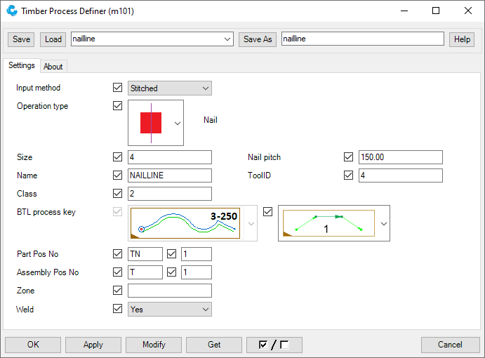
Nail lines
Image
| Option | Description | ||||
|---|---|---|---|---|---|
| Input method |
Image
|
Is most ideal for nail lines. | |||
|
Image
|
Is not practical for nail lines because start and end point of a nail line can coincide. |
||||
|
Image
|
Is not practical for nail lines because start and end point of a nail line can coincide. |
||||
| Operation type |
Image
 |
||||
| Size |
Use this value to set the size of the part to be created. |
||||
| Nail pitch |
The nail pitch to be applied on the machine. This parameter is not visible in the model. |
||||
| Name* |
The name of the part to be created. |
||||
| ToolID |
The ID to be assigned for the tool on the machine. |
||||
| Class* |
The color of the part to be created. |
||||
| BTL process key | Non applicable. | ||||
| Cut-through | Non applicable. | ||||
| Part Pos No* |
Part prefix and start number of the parts to be created. |
||||
| Assembly Pos No* |
Assembly prefix and start number of the parts to be created. |
||||
| Zone |
The zone in which the process should be included, normally the zone of the parts on which the milling is performed. |
||||
| Weld* |
Determine whether the operation is added to the element. Must always be set to Yes. If set to No, the operation will not be included in the export. |
||||
Glue lines and glue areas
Image

| Option | Description | ||||
|---|---|---|---|---|---|
| Input method |
Image
|
Is most ideal for glue lines. | |||
|
Image
|
Makes the glue line an open polygon. |
||||
|
Image
|
Makes the glue line a closed polygon. |
||||
| Operation type |
Image
 |
||||
| Size | Non applicable. | ||||
| Glue type |
Image
|
Creates a glue line with a fixed part size of 1*1. |
|||
|
Image
|
Creates a glue area. | ||||
| Name* | The name of the part to be created. | ||||
| ToolID |
The ID to be assigned for the tool on the machine. |
||||
| Class* | The color of the part to be created. | ||||
| BTL process key | Non applicable. | ||||
| Cut-through | Non applicable. | ||||
| Part Pos No* |
Part prefix and start number of the parts to be created. |
||||
| Assembly Pos No* | Assembly prefix and start number of the parts to be created. | ||||
| Zone |
The zone in which the process should be included, normally the zone of the parts on which the milling is performed. |
||||
| Weld* |
Determine whether the operation is added to the element. Must always be set to Yes. If set to No, the operation will not be included in the export. |
||||
Mill/saw lines
The processes for mill and saw lines are basically the same. The only difference is the tool that is invoked.
Image

| Option | Description | ||||
|---|---|---|---|---|---|
| Input method |
Image
|
Not intended for milling. | |||
|
Image
|
Makes the milling line an open polygon. | ||||
|
Image
|
Makes the milling line a closed polygon. | ||||
| Operation type |
Image
|
Inner mill line |
|||
|
Image
|
Outer mill line |
||||
|
Image
|
Inner saw line |
||||
|
Image
|
Outer saw line |
||||
| Size* |
Use this value to set the size of the part to be created. |
||||
| Depth |
The milling depth to be performed, if the depth is 0, the depth is executed on the machine as plate thickness. This parameter is not visible in the model. |
||||
| Name* | The name of the part to be created. | ||||
| Class* | The color of the part to be created. | ||||
| BTL process key |
Image
 |
Tools on the left of the material. |
|||
|
Image
 |
Tools on the right of the material. |
||||
| Cut-through |
Image
 |
Leave the choice of the cut-through to the machine. |
|||
|
Image
 |
No cut-through at the begin and/or at the end. | ||||
|
Image
 |
Cut-through at the begin, not at the end. |
||||
|
Image
 |
Cut-through at the end, not at the begin. |
||||
|
Image
 |
Cut-through at the begin and at the end. |
||||
| Part Pos No* | Part prefix and start number of the parts to be created. | ||||
| Assembly Pos No* | Assembly prefix and start number of the parts to be created. | ||||
| Zone |
The zone in which the process should be included, normally the zone of the parts on which the milling is performed. |
||||
| Weld* |
Determine whether the operation is added to the element. Must always be set to Yes. If set to No, the operation will not be included in the export. |
||||
Note: The combination of Operation type, BTL process key and the drawing direction determines the final direction and side of the milling process on the machine.
Example
Image

We always draw the milling lines from the side of the element that we are looking at. So place the element in front of you as in the image above and if you want to provide the other side with milling lines, then rotate the element 180° around the Z axis.
1. We want to position a mill line around the element and we draw counterclockwise, so in the image above from the point at grid 2 in the Z direction, next in the Y direction.
Next we select Operation type
Image
And for BTL Process key
Image

The result in the model looks like this:
Image

2. We want to position a mill line in an opening and we draw counterclockwise.
Next we select Operation type
Image
And for BTL Process key
Image

The result in the model looks like this:
Image

We can also draw clockwise, but then the Operation type and the BTL Process key must also be reversed.
Lockout areas
Image

| Option | Description | ||||
|---|---|---|---|---|---|
| Input method | Non applicable. | ||||
| Operation type |
Image
 |
Lockout area |
|||
| Size |
The thickness of the contour plate which is created as a part. |
||||
| Lock out area type |
Image
|
All nails and (parts of) glue lines that are in this area are not executed. |
|||
|
Image
|
All nails that are in this area are not executed. |
||||
|
Image
 |
All (parts of) glue lines that are in this area are not executed. |
||||
| Name* | The name of the part to be created. | ||||
| ToolID | Non applicable. | ||||
| Class* | The color of the part to be created. | ||||
| BTL process key | Non applicable. | ||||
| Cut-through | Non applicable. | ||||
| Part Pos No* | Part prefix and start number of the parts to be created. | ||||
| Assembly Pos No* | Assembly prefix and start number of the parts to be created. | ||||
| Zone |
The zone in which the process should be included, normally the zone of the parts on which the milling is performed. |
||||
| Weld* |
Determine whether the operation is added to the element. Must always be set to Yes. If set to No, the operation will not be included in the export. |
||||
Tab About
Information about the version date. This date is indicative and can therefore be different even though the tool has the same content.
Image

All rights reserved. No conclusions can be associated to the representation of the pictures in relation to the operating systems under which Tekla Structures runs.
This work is licensed under the Creative Commons Attribution-NonCommercial-NoDerivatives 4.0 International License. To view a copy of this license, visit http://creativecommons.org/licenses/by-nc-nd/4.0/ or send a letter to Creative Commons, 444 Castro Street, Suite 900, Mountain View, California, 94041, USA.
Back to top