Release Info Tekla Structures 2021
2021
Tekla Structures
Environment
Netherlands
Construsoft European
In Tekla Structures 2021, selecting parts by using a crossing selection works in another way than in earlier Tekla Structures versions, for detailed information, see chapter Modeling > Selecting part by using the crossing selection.
In Tekla Structures 2021, changing some options in particular reinforcement system components works in another way than in earlier Tekla Structures versions, for detailed information, see chapter System components > Changing options in (reinforcement) system components.
The Release Info Tekla Structures 2021 includes the following topics:
General
Tekla Structures 2021 videos
Tekla Structures 2021 provides many new options, improvements and fixes. These are all explained in this Release Info. Besides, some videos are available in which these functionalities are explained.

You can check the following videos (per segment):
Tekla Structures 2021 What's new for Steel
Tekla Structures 2021 What's new for Precast
Tekla Structures 2021 What's new for Cast-in-Place
Tekla Structures 2021 What's new for Structural Engineers
Image
You can check the following videos (per segment):
Tekla Structures 2021 What's new for Steel
Tekla Structures 2021 What's new for Precast
Tekla Structures 2021 What's new for Cast-in-Place
Tekla Structures 2021 What's new for Structural Engineers
New options in the side pane
Tekla Structures 2021 includes several new options in the side pane.
Command Visualizer expanded
In the side pane, in the Visualizer command in the tab Phases, you now have a new list box in which you can select at which level/part you want to visualize the phases. The option Assembly is still the default option:
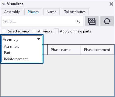
Filtering by phases did not always work correct. This has now been fixed.
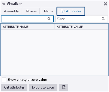
The command Visualizer in the side pane now includes a new tab Attributes. Here you can see which variables, but also which user-defined attributes have been defined.
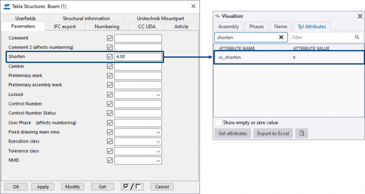
By getting the attributes of a selected part (button Get attributes), these will be displayed, and you can filter the attributes:
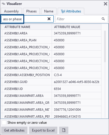
Besides you can also use the search term “or”:
Image
Filtering by phases did not always work correct. This has now been fixed.
The command Visualizer in the side pane now includes a new tab Attributes. Here you can see which variables, but also which user-defined attributes have been defined.
Image
By getting the attributes of a selected part (button Get attributes), these will be displayed, and you can filter the attributes:
Image
Besides you can also use the search term “or”:
Image
Construsoft Online added
In Tekla Structures, you can run various commands in the side pane, such as accessing the Applications & components catalog or adding reference models and point clouds.
The side pane has been expanded in Tekla Structures 2021 and now includes Construsoft Online:
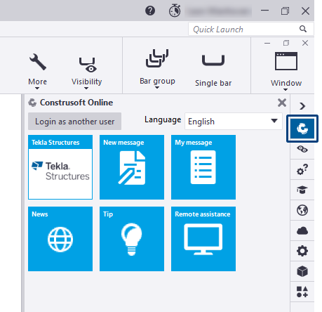
This is the link to the Construsoft Supportdesk (Topdesk) where you can find a large collection of frequently asked questions, tips and news. In addition, you can create notifications and view the status of your notifications.
To have access to this service, log in with your Topdesk account. If you are not logged in, you will only see two tiles. If desired, you can change the language in Construsoft Online.
The Construsoft Supportdesk contains many references to articles in the Tekla User Assistance (TUA) where all information is in one place; you can quickly find the information you need by using the search function.
The Construsoft Supportdesk is maintained continuously by Construsoft and kept up to date. If new articles are added by Construsoft, for example if news is available, an exclamation mark automatically appears when you start Tekla Structures:
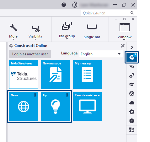
Once the article has been viewed; the exclamation mark will automatically disappear.
The side pane has been expanded in Tekla Structures 2021 and now includes Construsoft Online:
Image
This is the link to the Construsoft Supportdesk (Topdesk) where you can find a large collection of frequently asked questions, tips and news. In addition, you can create notifications and view the status of your notifications.
To have access to this service, log in with your Topdesk account. If you are not logged in, you will only see two tiles. If desired, you can change the language in Construsoft Online.
The Construsoft Supportdesk contains many references to articles in the Tekla User Assistance (TUA) where all information is in one place; you can quickly find the information you need by using the search function.
The Construsoft Supportdesk is maintained continuously by Construsoft and kept up to date. If new articles are added by Construsoft, for example if news is available, an exclamation mark automatically appears when you start Tekla Structures:
Image
Once the article has been viewed; the exclamation mark will automatically disappear.
New timber related ribbon available
When you start Tekla Structures 2021 with the Timber Detailer role, the ribbon now includes an extra Timber tab:
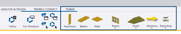
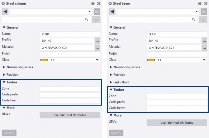
In addition, the properties of the model objects now include the new group Timber with associated fields:
Image
In addition, the properties of the model objects now include the new group Timber with associated fields:
Image
Updating model templates
In case you have created model templates in earlier Tekla Structures versions, you must update the templates to use them hassle-free in Tekla Structures 2021.
Click here for the general step plan.
Click here for the general step plan.
Copy customized ribbon and shortcuts to Tekla Structures 2021
You can copy your customized ribbon and shortcuts (after installing Tekla Structures 2021) from an older Tekla Structures version to Tekla Structures 2021.
Copy the ribbon
You can copy your customized ribbon from an older Tekla Structures version to Tekla Structures 2021.
NOTE: If you copy your customized ribbon, new available (in Tekla Structures 2021) command buttons will be missing, for example the new command Batch-editor in the Model Editor for quickly copying all edits from a source assembly or cast unit to specified target assemblies or cast units in one go:

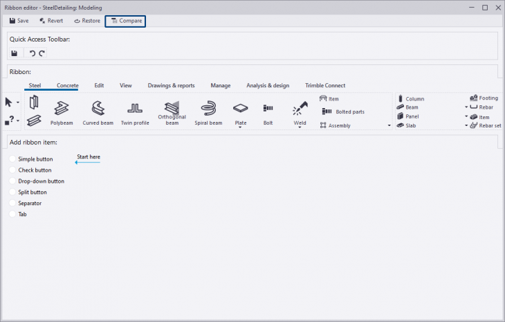
You can also first compare the "old" ribbon with the new "standard" ribbon in Tekla Structures 2021 via File > Settings > Ribbon > Compare in both Model and Drawing Editor:
You will see the differences between your customized ribbon and the "default" Tekla Structures 2021 ribbon, for example the new Batch-editor command:
You can now choose to add the missing command buttons or to use the new "standard" ribbon.
You can do next to copy your customized ribbon:
1. In the Windows Explorer, go to the folder (depends on the Tekla Structures-version)
or the folder
2. The *.xml file:
3. Copy this *.xml file to the folder
Note that the ribbon file name is determined by the Tekla Structures configuration you are using. For example, for the Steel Detailing configuration, the file name albl_up_Steel_Detailing - main_menu.xml is used. Because there are three new configurations available in Tekla Structures 2021, the following table shows the available configurations and their file names:
* New in Tekla Structures 2021. These options are only available if you have a subscription.
Click here for more detailed information about copying the ribbon.
Copy shortcuts
To copy shortcuts from an earlier Tekla Structures version to Tekla Structures 2021:
1. In an earlier Tekla Structures version, go to File > Settings > Keyboard shortcuts.
2. Click on the button Export, save the *.xml file on the desired location with the desired name.
3. In Tekla Structures 2021, go to File > Settings > Keyboard shortcuts.
4. Click on the button Import, select the *.xml file and click on the button Open, the shortcuts are now imported.
You can copy the exported *.xml file to any computer and next import the file in Tekla Structures 2021.
Copy the ribbon
You can copy your customized ribbon from an older Tekla Structures version to Tekla Structures 2021.
NOTE: If you copy your customized ribbon, new available (in Tekla Structures 2021) command buttons will be missing, for example the new command Batch-editor in the Model Editor for quickly copying all edits from a source assembly or cast unit to specified target assemblies or cast units in one go:
Image
You can also first compare the "old" ribbon with the new "standard" ribbon in Tekla Structures 2021 via File > Settings > Ribbon > Compare in both Model and Drawing Editor:
Image
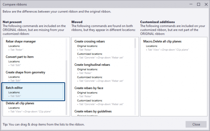
You will see the differences between your customized ribbon and the "default" Tekla Structures 2021 ribbon, for example the new Batch-editor command:
Image
You can now choose to add the missing command buttons or to use the new "standard" ribbon.
You can do next to copy your customized ribbon:
1. In the Windows Explorer, go to the folder (depends on the Tekla Structures-version)
C:\Users\<user>\AppData\Local\Trimble\TeklaStructures\<older version>\UI\Ribbons\ or the folder
C:\Users\<user>\AppData\Local\Trimble\Tekla Structures\<older version>\UI\Ribbons\2. The *.xml file:
albl_up_<license>--main_menu.xml contains the customized ribbon.3. Copy this *.xml file to the folder
C:\Users\<user>\AppData\Local\Trimble\Tekla Structures\2021.0\UI\Ribbons.Note that the ribbon file name is determined by the Tekla Structures configuration you are using. For example, for the Steel Detailing configuration, the file name albl_up_Steel_Detailing - main_menu.xml is used. Because there are three new configurations available in Tekla Structures 2021, the following table shows the available configurations and their file names:
| Name configuration | File name |
|---|---|
| Construction Modeling | albl_up_Construction_Modeling |
| Developer | albl_up_Developer |
| Drafter | albl_up_Drafter |
| Educational | albl_up_Educational |
| Engineering | albl_up_Engineering |
| Full | albl_up_Full |
| Precast Concrete Detailing | albl_up_PC_Detailing |
| Rebar Detailing | albl_up_Rebar_Detailing |
| Steel Detailing | albl_up_Steel_Detailing |
| Primary | albl_up_Tekla_Structures_Primary |
| Project Viewer | albl_up_Viewer |
| Carbon * | albl_up_Carbon |
| Graphite * | albl_up_Graphite |
| Diamond * | albl_up_Diamond |
* New in Tekla Structures 2021. These options are only available if you have a subscription.
Click here for more detailed information about copying the ribbon.
Copy shortcuts
To copy shortcuts from an earlier Tekla Structures version to Tekla Structures 2021:
1. In an earlier Tekla Structures version, go to File > Settings > Keyboard shortcuts.
2. Click on the button Export, save the *.xml file on the desired location with the desired name.
3. In Tekla Structures 2021, go to File > Settings > Keyboard shortcuts.
4. Click on the button Import, select the *.xml file and click on the button Open, the shortcuts are now imported.
You can copy the exported *.xml file to any computer and next import the file in Tekla Structures 2021.
Messages for path references to non-existing folders
In Tekla Structures 2021 a message appears in case one or more advanced options refer to non-existing folders:
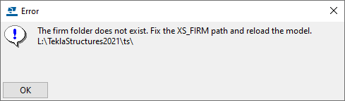
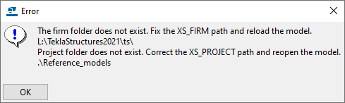
Make sure the folder is in the concerned location or correct the path reference for the affected advanced option(s). Next reopen the model.
Image
Image
Make sure the folder is in the concerned location or correct the path reference for the affected advanced option(s). Next reopen the model.
Adjusted profile database for hollow core slab profiles
For modeling hollow core slabs in earlier Tekla Structures versions, you could use various hollow core slab profiles from different suppliers (such as VBI, Dycore, Structo etc.):
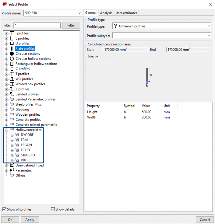
Since Tekla Structures 2020 Service Pack 3, these profiles are no longer available in the default Profile Catalog.
It is possible that there are changes in the hollow core slabs, for example changes in hollow core slabs dimensions, hollow core slabs that are no longer available, etc..
In order to provide Tekla Structures users with the latest developments, more often suppliers are making their products available on Tekla Warehouse. The suppliers are of course responsible for their products.
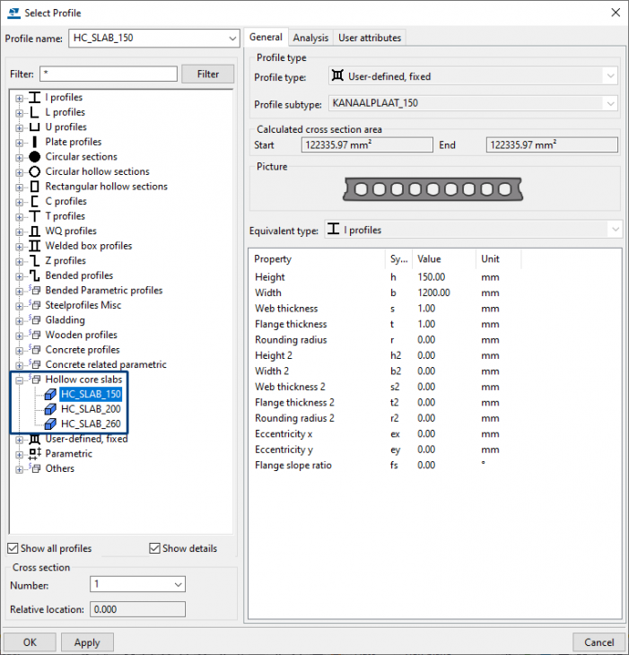
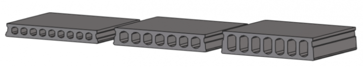
To model hollow core slabs that are not supplier related, from Tekla Structures 2020 Service Pack 3 on, some "fictitious" hollow core slab profiles are available:
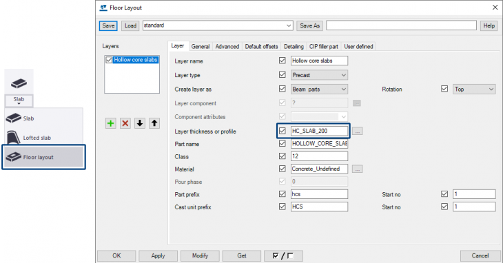
The components and tools with which you can model and edit hollow core slabs have also been adjusted in terms of settings, such as the Floor Layout tool:
...and also system components Area filled with slabs (61) and Area filled with slabs (62). The accompanying file pasplaat.dat has also been modified:
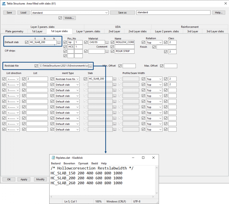
If you want to use the fitting plates file with the various suppliers, it is now available with the name fitplates_diverse.dat and stored in the folder: ..:\TeklaStructures\2021.0\Environments\ConstrusoftEuropean\Config.
Image
Since Tekla Structures 2020 Service Pack 3, these profiles are no longer available in the default Profile Catalog.
It is possible that there are changes in the hollow core slabs, for example changes in hollow core slabs dimensions, hollow core slabs that are no longer available, etc..
In order to provide Tekla Structures users with the latest developments, more often suppliers are making their products available on Tekla Warehouse. The suppliers are of course responsible for their products.
To model hollow core slabs that are not supplier related, from Tekla Structures 2020 Service Pack 3 on, some "fictitious" hollow core slab profiles are available:
Image
Image
The components and tools with which you can model and edit hollow core slabs have also been adjusted in terms of settings, such as the Floor Layout tool:
Image
...and also system components Area filled with slabs (61) and Area filled with slabs (62). The accompanying file pasplaat.dat has also been modified:
Image
If you want to use the fitting plates file with the various suppliers, it is now available with the name fitplates_diverse.dat and stored in the folder: ..:\TeklaStructures\2021.0\Environments\ConstrusoftEuropean\Config.
Value field LENGTH adjusted in several reports
In Tekla Structures 2021 the value field
● PDF-material-list.pdf.rpt
● PDF-material-state-list.pdf.rpt
● PDF-saw-list-part-assembly.pdf.rpt
● material-list.rpt
● material-state-list.rpt
● profiles-list.rpt
● saw list with angles.rpt
● saw list part assembly.rpt
● saw list.rpt
New report to be able to quickly select the profiles with a double cut: id_part-list-double-cut.rpt.
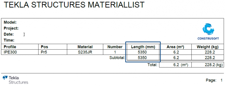
As a result, the so-called gross length is now shown in the reports:
In the drawing:
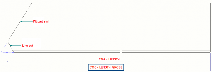
LENGTH in the following reports has been adjusted to LENGTH_GROSS. The reason is the profiles with a double cut (fit part end + line cut) so that the longest length is listed.● PDF-material-list.pdf.rpt
● PDF-material-state-list.pdf.rpt
● PDF-saw-list-part-assembly.pdf.rpt
● material-list.rpt
● material-state-list.rpt
● profiles-list.rpt
● saw list with angles.rpt
● saw list part assembly.rpt
● saw list.rpt
New report to be able to quickly select the profiles with a double cut: id_part-list-double-cut.rpt.
As a result, the so-called gross length is now shown in the reports:
Image
In the drawing:
Image
|
Image
|
In case you have customized such reports or created reports of your own in earlier Tekla Structures versions, check them and adjust them if needed (after copying them to your Tekla Structures 2021 TS folder) so that they are up to date again in Tekla Structures 2021. |
New predefined rules available in the Template Editor
Tekla Structures already included several predefined rules (as a basis) in rows in the Template Editor.
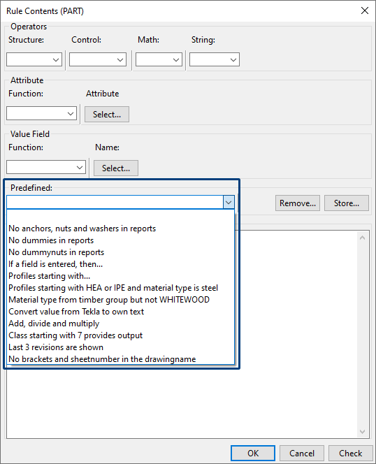
Open the Template Editor (via File > Editors > Template Editor) in Tekla Structures and create or open an existing template/report and double-click on a row. The following dialog box appears:
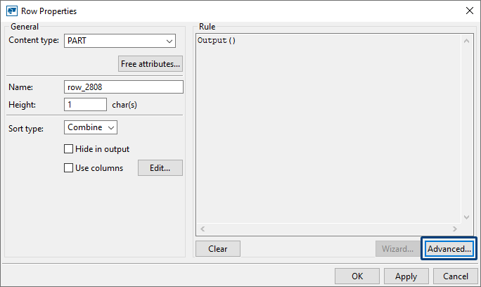
Next click the button Advanced, you can now select predefined rules in the drop-down list:
When you select a line in the drop-down list, the content is shown immediately:
You can save your predefined rules (with adapted conditions) as follows:
Modify a condition and click button Store, the following dialog box appears:
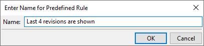
Enter the name for the predefined rule and click OK, the rule is now stored and visible in the drop-down list immediately:
Besides the predefined rules Tekla Structures 2021 now also includes several predefined formulas (as a basis) in value fields in the Template Editor.
In a template or list, double-click a value field. The following dialog box appears:
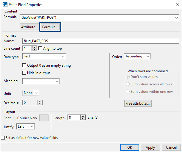
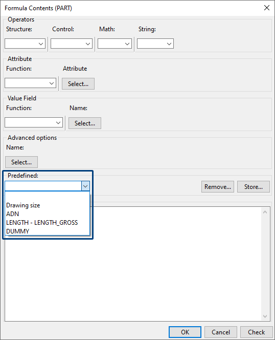
Next click on the button Formula, you can now select a predefined formula from the drop-down list:
When you select a formula in the drop-down list, the content is entered directly:
All modifications, for both rules and formulas, are stored in the file rules.txt in the folder:
C:\TeklaStructures\2021.0\Environments\ConstrusoftEuropean\General\template\settings
Restart Tekla Structures to be able to use the modifications in all Tekla Structures models.
Open the Template Editor (via File > Editors > Template Editor) in Tekla Structures and create or open an existing template/report and double-click on a row. The following dialog box appears:
Image
Next click the button Advanced, you can now select predefined rules in the drop-down list:
Image
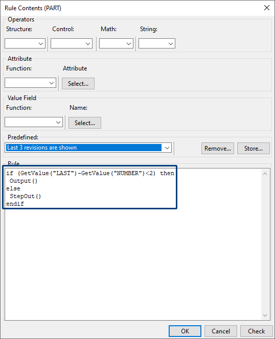
When you select a line in the drop-down list, the content is shown immediately:
Image
You can save your predefined rules (with adapted conditions) as follows:
Modify a condition and click button Store, the following dialog box appears:
Image
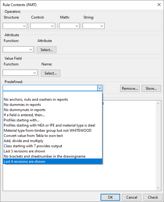
Enter the name for the predefined rule and click OK, the rule is now stored and visible in the drop-down list immediately:
Image
Besides the predefined rules Tekla Structures 2021 now also includes several predefined formulas (as a basis) in value fields in the Template Editor.
In a template or list, double-click a value field. The following dialog box appears:
Image
Next click on the button Formula, you can now select a predefined formula from the drop-down list:
Image
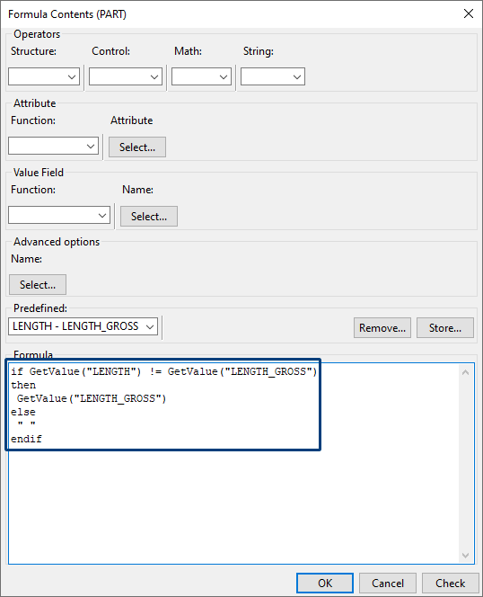
When you select a formula in the drop-down list, the content is entered directly:
Image
All modifications, for both rules and formulas, are stored in the file rules.txt in the folder:
C:\TeklaStructures\2021.0\Environments\ConstrusoftEuropean\General\template\settings
Restart Tekla Structures to be able to use the modifications in all Tekla Structures models.
Interoperability
New tool CS IFC Extender (ML126)
Tekla Structures includes the option to export a Tekla Structures model (or a part of it) to an IFC file.
For this export, default property set are available in which you can define which attributes you want to include in the export to IFC. Click here for more detailed information about defining property sets for export to IFC.
However, in the export to IFC, some attributes are filled in in a certain way but you possibly may want to have another value for some attributes for the purpose of some agreements that have been made regarding to exchanging information, or fields that cannot be filled in by default in Tekla Structures.
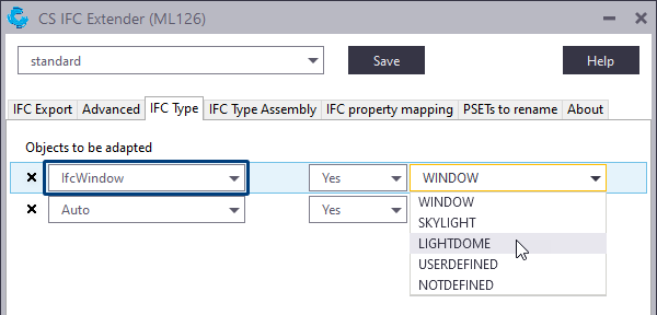
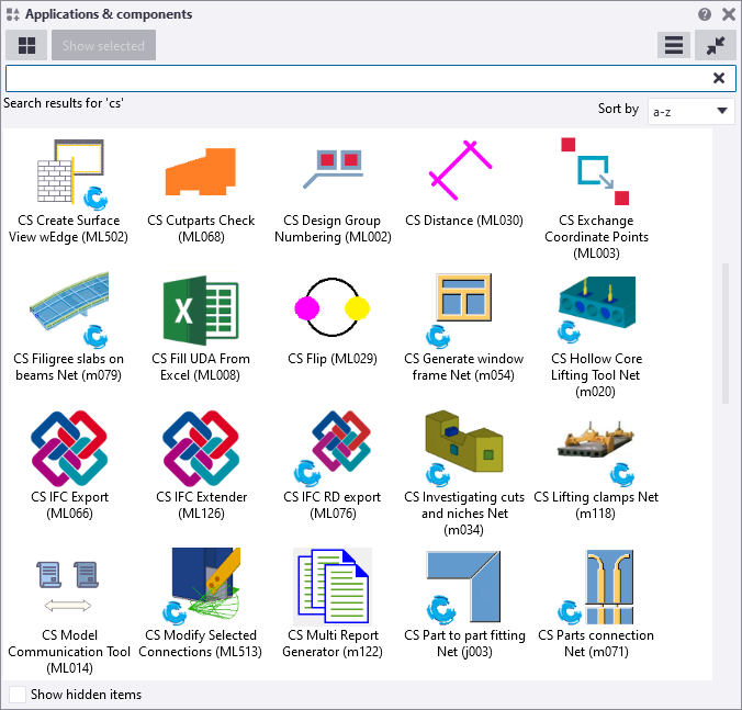
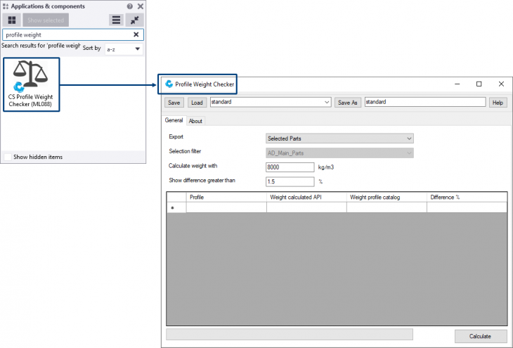
For this, the tool CS IFC Extender (ML126) is now available. The tool is available in the Applications & components database:

In the tool CS IFC Extender (ML126), the tab IFC Export includes the same options as in the Export to IFC dialog (via File> Export> IFC):

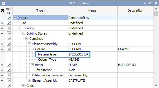
When you create an IFC export in Tekla Structures:
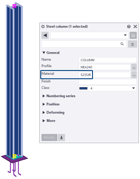
...by default, the material group and the material grade are included in the IFC file:
You possibly may want to include only the material grade in the IFC:
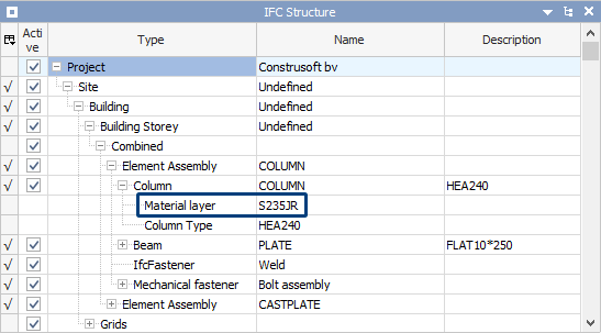
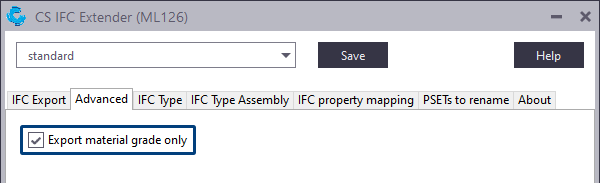
For this, in the Advanced tab you can enable the option Export material grade only:
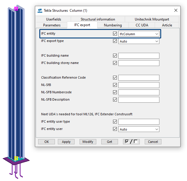
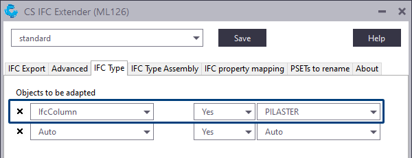
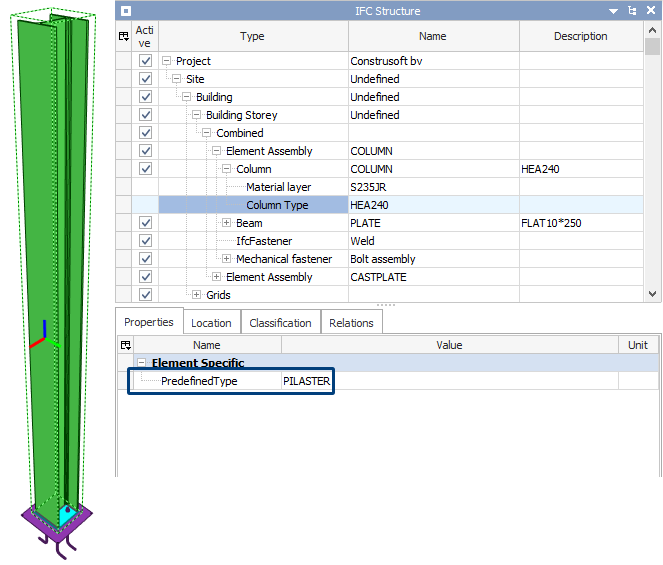
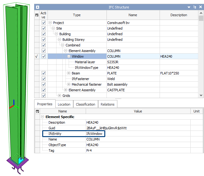
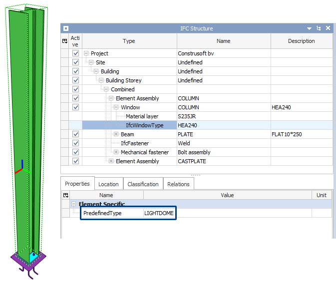
In addition, on the IFC Type tab in the tool, you can choose per IFC entity on part level which PredefinedType this should be. You can find the IFC entity in Tekla Structures in the IFC export tab:
In Tekla Structures (make sure the button Select objects in components
 in the Selection toolbar is enabled):
In the tool CS IFC Extender (ML126), the IFC entity IfcColumn should be PredefinedType PILASTER:
In the IFC:
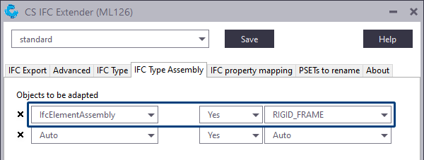
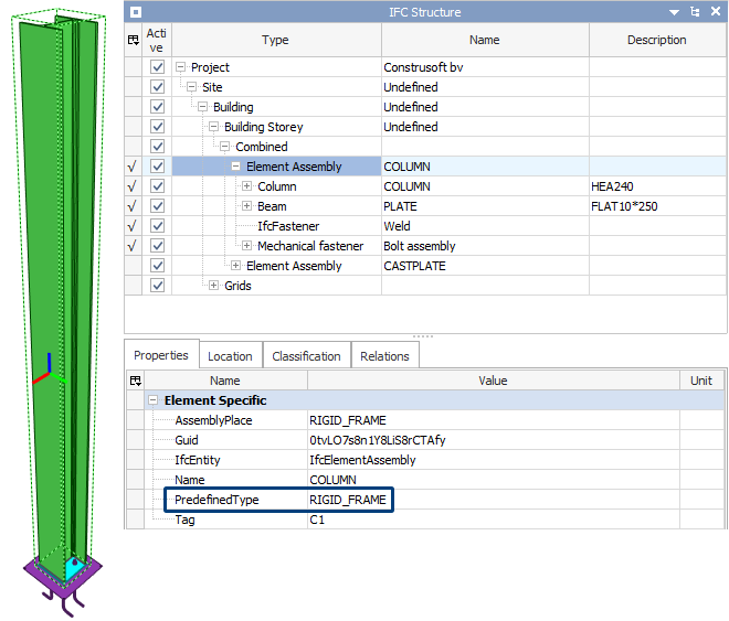
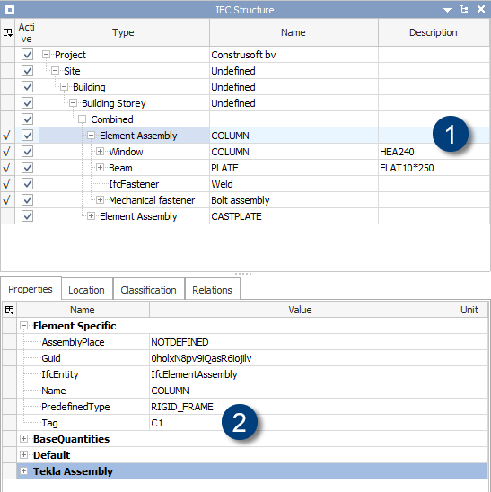
In addition, on the IFC Type Assembly tab in the tool, you can choose per IFC entity on assembly level which PredefinedType this should be. You can find the IFC entity in Tekla Structures in the IFC export tab:
In Tekla Structures (make sure the button Select assemblies
 in the Selection toolbar is enabled):
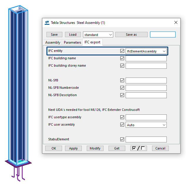
In the tool CS IFC Extender (ML126), the IFC entity IfcElementAssembly should be PredefinedType RIGID_FRAME:
In the IFC:
When you make the above changes (such as the PredefinedType for the IFC entity IfcColumn in the example above) by using the tool CS IFC Extender (ML126), this applies to all parts that include this entity.
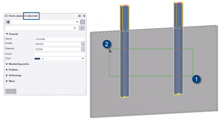
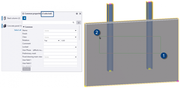
However, in Tekla Structures 2021 you can now also adjust the PredefinedType by part or by assembly instead of all parts or assemblies with a certain entity. In Tekla Structures, in the user-defined attributes of parts in the IFC export tab, you have a new field IFC entity user type on part level and IFC usertype assembly on assembly level in the IFC export tab:

User-defined attributes for part User-defined attributes for assemblies
You can also adjust the IFC entity by part or by assembly in Tekla Structures 2021. In Tekla Structures, in the part user-defined attributes in the IFC export tab, you have a new field IFC entity user at part level and IFC user assembly at assembly level in the IFC export tab:
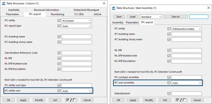
The IFC export tab has also been rearranged and regrouped.
You fill in these fields in the user-defined attributes of the part or assembly based on the values which are available in the IFC Type tab (for parts) or IFC Type Assembly tab (for assemblies) in the tool CS IFC Extender (ML126), for example:
The user-defined attributes of the part in Tekla Structures:
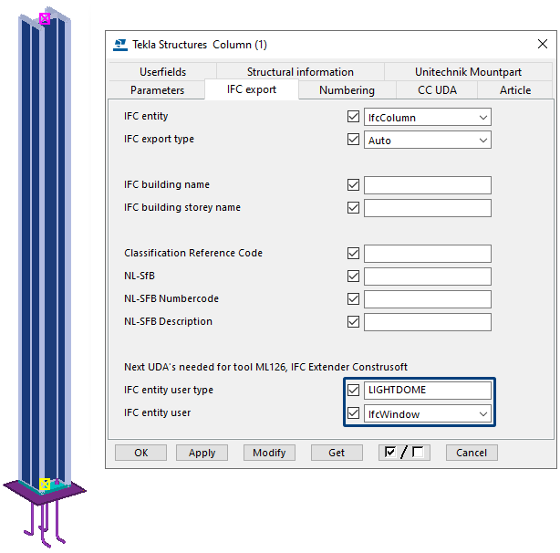
In the IFC:
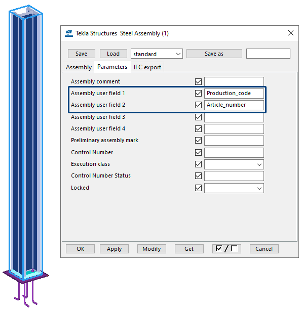
When you create an IFC export from Tekla Structures via File> Export> IFC, for some entities there is no option to change these. For example, description of the assembly (1) that is currently not filled in, or the tag of the assembly where you might want an article number (2).
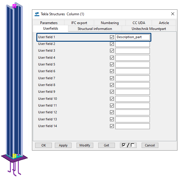
On part level, for example the description of the part (1) where you might prefer something else.
In the tool CS IFC Extender (ML126) you can use the IFC property mapping tab for this. In here you can write the content of a user-defined attribute in Tekla Structures to a specific IFC property per IFC entity.
In the example below, we have entered the following user-defined attributes at assembly level in Tekla Structures:
At part level we have entered the following user-defined attribute:
In the tool CS IFC Extender (ML126) we have defined the following:
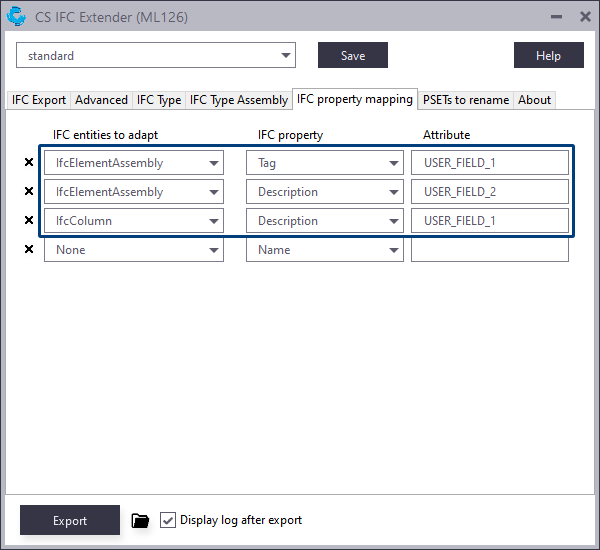
When you enter user-defined attributes in Tekla Structures, you must next enter the name of the user-defined attribute in the Attribute column.
For more information about user-defined attributes value fields, check this article.
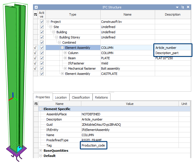
In the IFC:
For this export, default property set are available in which you can define which attributes you want to include in the export to IFC. Click here for more detailed information about defining property sets for export to IFC.
However, in the export to IFC, some attributes are filled in in a certain way but you possibly may want to have another value for some attributes for the purpose of some agreements that have been made regarding to exchanging information, or fields that cannot be filled in by default in Tekla Structures.
For this, the tool CS IFC Extender (ML126) is now available. The tool is available in the Applications & components database:
Image
In the tool CS IFC Extender (ML126), the tab IFC Export includes the same options as in the Export to IFC dialog (via File> Export> IFC):
Image
When you create an IFC export in Tekla Structures:
Image
...by default, the material group and the material grade are included in the IFC file:
Image
You possibly may want to include only the material grade in the IFC:
Image
For this, in the Advanced tab you can enable the option Export material grade only:
Image
In addition, on the IFC Type tab in the tool, you can choose per IFC entity on part level which PredefinedType this should be. You can find the IFC entity in Tekla Structures in the IFC export tab:
In Tekla Structures (make sure the button Select objects in components
Image
Image
In the tool CS IFC Extender (ML126), the IFC entity IfcColumn should be PredefinedType PILASTER:
Image
In the IFC:
Image
In addition, on the IFC Type Assembly tab in the tool, you can choose per IFC entity on assembly level which PredefinedType this should be. You can find the IFC entity in Tekla Structures in the IFC export tab:
In Tekla Structures (make sure the button Select assemblies
Image
Image
In the tool CS IFC Extender (ML126), the IFC entity IfcElementAssembly should be PredefinedType RIGID_FRAME:
Image
In the IFC:
Image
When you make the above changes (such as the PredefinedType for the IFC entity IfcColumn in the example above) by using the tool CS IFC Extender (ML126), this applies to all parts that include this entity.
However, in Tekla Structures 2021 you can now also adjust the PredefinedType by part or by assembly instead of all parts or assemblies with a certain entity. In Tekla Structures, in the user-defined attributes of parts in the IFC export tab, you have a new field IFC entity user type on part level and IFC usertype assembly on assembly level in the IFC export tab:
Image
User-defined attributes for part User-defined attributes for assemblies
You can also adjust the IFC entity by part or by assembly in Tekla Structures 2021. In Tekla Structures, in the part user-defined attributes in the IFC export tab, you have a new field IFC entity user at part level and IFC user assembly at assembly level in the IFC export tab:
Image
The IFC export tab has also been rearranged and regrouped.
You fill in these fields in the user-defined attributes of the part or assembly based on the values which are available in the IFC Type tab (for parts) or IFC Type Assembly tab (for assemblies) in the tool CS IFC Extender (ML126), for example:
Image
The user-defined attributes of the part in Tekla Structures:
Image
In the IFC:
Image
Image
When you create an IFC export from Tekla Structures via File> Export> IFC, for some entities there is no option to change these. For example, description of the assembly (1) that is currently not filled in, or the tag of the assembly where you might want an article number (2).
Image
On part level, for example the description of the part (1) where you might prefer something else.
Image
In the tool CS IFC Extender (ML126) you can use the IFC property mapping tab for this. In here you can write the content of a user-defined attribute in Tekla Structures to a specific IFC property per IFC entity.
In the example below, we have entered the following user-defined attributes at assembly level in Tekla Structures:
Image
At part level we have entered the following user-defined attribute:
Image
In the tool CS IFC Extender (ML126) we have defined the following:
Image
When you enter user-defined attributes in Tekla Structures, you must next enter the name of the user-defined attribute in the Attribute column.
For more information about user-defined attributes value fields, check this article.
In the IFC:
Image
Modeling
Selecting part by using the crossing selection
In Tekla Structures 2021, selecting parts with a crossing selection works differently than in previous Tekla Structures versions when the parts display is set to Parts wireframe (Ctrl + 1) or Parts shaded wireframe (Ctrl + 2) and the component part display is set to Components wireframe (Shift + 1) or Components shaded wireframe (Shift + 2), to select the objects from right to left that are completely or partly in the rectangular selection area.
Earlier Tekla Structures versions:
Tekla Structures 2021:
In Tekla Structures 2021 SP1 it will work as it did in earlier Tekla Structures versions.
Earlier Tekla Structures versions:
Image
Tekla Structures 2021:
Image
In Tekla Structures 2021 SP1 it will work as it did in earlier Tekla Structures versions.
Batch editing of assemblies or cast units
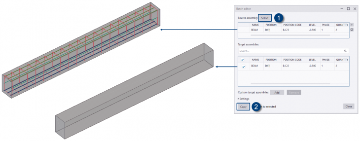
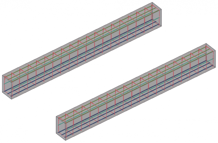
In Tekla Structures 2021, you can now quickly copy all edits from a source assembly or cast unit to specified target assemblies or cast units in one go. The new tool Batch-editor reduces the amount of repetitive work in situations where you need to edit identical assemblies or cast units by modifying the object geometry or by changing the part properties:

Batch editor works with identical assemblies and cast units that have the same position number, or with very similar but differently numbered assemblies and cast units.
For detailed information on how to use the new Batch-editor, see the Release Notes Tekla Structures 2021.
Click here for a steel-related video about the Batch-editor.
Click here for a concrete-related video about the Batch-editor.
Image
Batch editor works with identical assemblies and cast units that have the same position number, or with very similar but differently numbered assemblies and cast units.
Image
Image
For detailed information on how to use the new Batch-editor, see the Release Notes Tekla Structures 2021.
Click here for a steel-related video about the Batch-editor.
Click here for a concrete-related video about the Batch-editor.
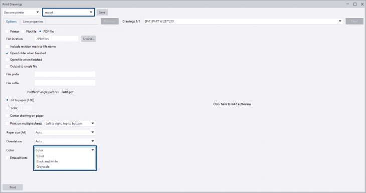
Print PDF reports in color
You now have the option to print PDF reports in color:
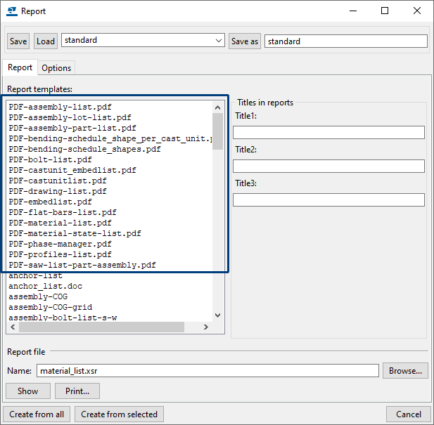
For this, in Tekla Structures 2021 the setting report is available in the Print Drawing dialog box (Shift + P). You can set the print option to use in the Color drop-down list:
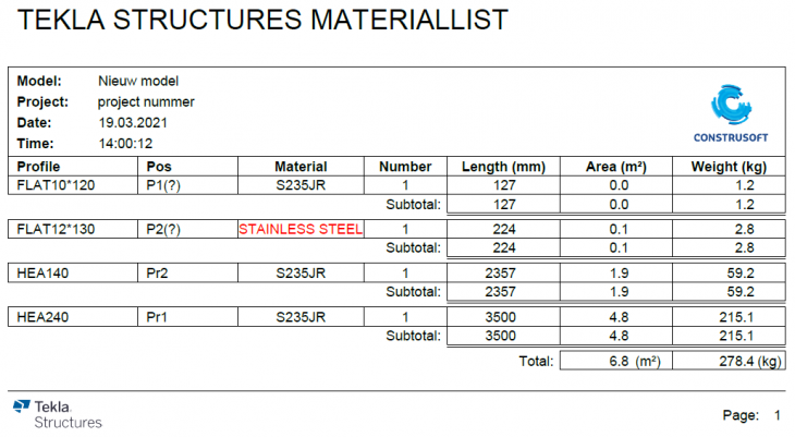
Next click the Save button and print the desired PDF report (s). By default, the PDF reports supplied by Construsoft do not include colors, but you can adjust them in the Template Editor if desired.
As an example, the report PDF-material-list.pdf has been modified and shows a material quality not equal to S235JR in a red color:
Image
For this, in Tekla Structures 2021 the setting report is available in the Print Drawing dialog box (Shift + P). You can set the print option to use in the Color drop-down list:
Image
Next click the Save button and print the desired PDF report (s). By default, the PDF reports supplied by Construsoft do not include colors, but you can adjust them in the Template Editor if desired.
As an example, the report PDF-material-list.pdf has been modified and shows a material quality not equal to S235JR in a red color:
Image
Adjusted names of the Construsoft tools in the Application & components database
The names of the Construsoft tools in the Applications & components database have been adjusted:
In addition, many tools have also been renamed in the dialog box so that they now match:
Image
In addition, many tools have also been renamed in the dialog box so that they now match:
Image
System components
Tensioner central gusset (18)
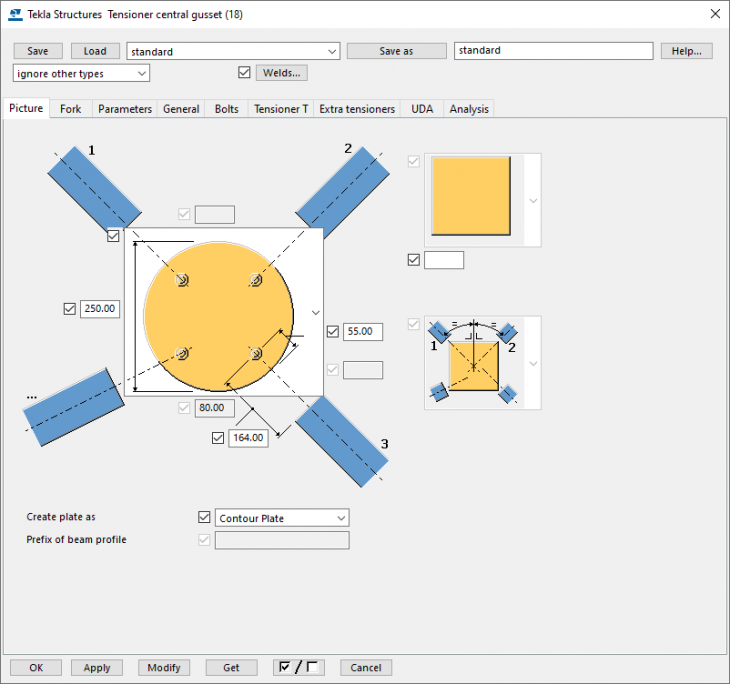
Tekla Structures includes system component Tensioner central gusset (18) for creating a gusset plate to connect bracing bars:
System component Tensioner central gusset (18) has now been taken over by Tekla. You can still use the Willems Anchor and Detan settings in the system component.
As Tekla took over the system component, note the following:
When you created settings for system component Tensioner central gusset (18) in earlier Tekla Structures versions, these settings were saved as follows:
<name_setting>.j90000018
So, the file extension was *. j90000018.
From Tekla Structures 2021, the settings are saved with file extension *. j80000018.
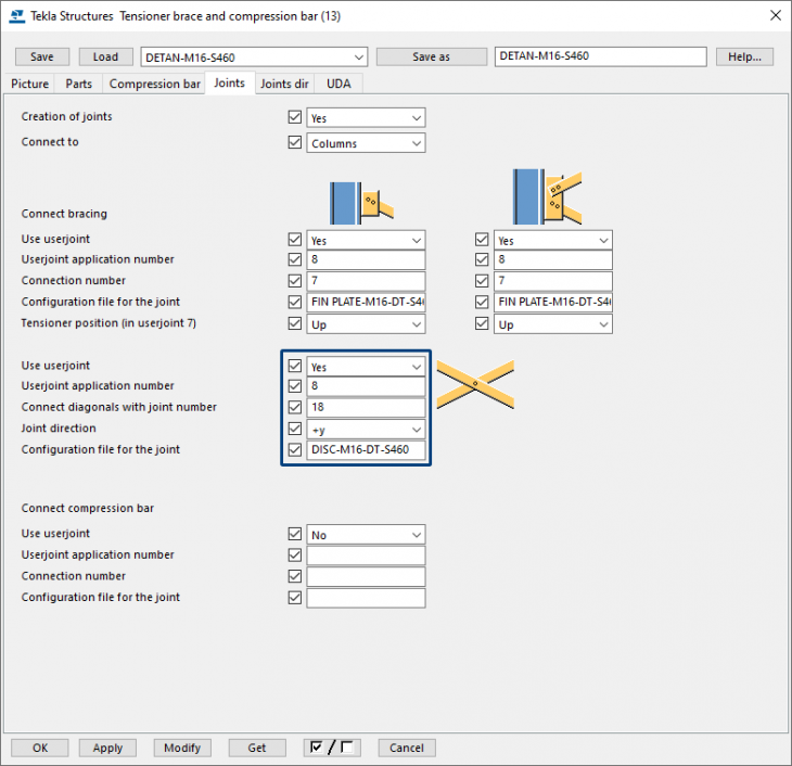
In addition, the settings of system component Tensioner central gusset (18) can be applied in system component Tensioner brace and compression bar (13):
Again, when you have created settings for system component Tensioner brace and compression bar (13) in earlier Tekla Structures versions, you must save these settings once so that they are up to date in Tekla Structures 2021.
Image
System component Tensioner central gusset (18) has now been taken over by Tekla. You can still use the Willems Anchor and Detan settings in the system component.
As Tekla took over the system component, note the following:
When you created settings for system component Tensioner central gusset (18) in earlier Tekla Structures versions, these settings were saved as follows:
<name_setting>.j90000018
So, the file extension was *. j90000018.
From Tekla Structures 2021, the settings are saved with file extension *. j80000018.
|
Image
|
This means that you have to rename the file extensions of the settings you created in earlier Tekla Structures versions to the new file extension (after copying them to your Tekla Structures 2021 TS folder) so that they are up to date in Tekla Structures 2021. |
In addition, the settings of system component Tensioner central gusset (18) can be applied in system component Tensioner brace and compression bar (13):
Image
Again, when you have created settings for system component Tensioner brace and compression bar (13) in earlier Tekla Structures versions, you must save these settings once so that they are up to date in Tekla Structures 2021.
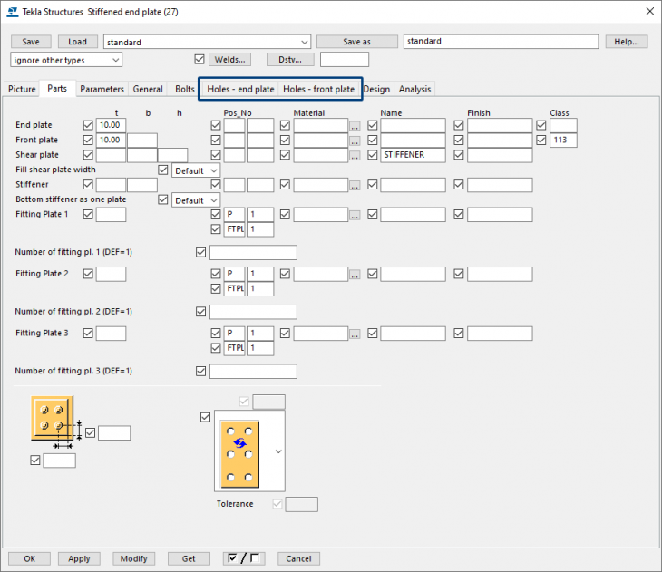
Stiffened end plate (27)
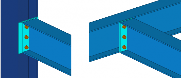
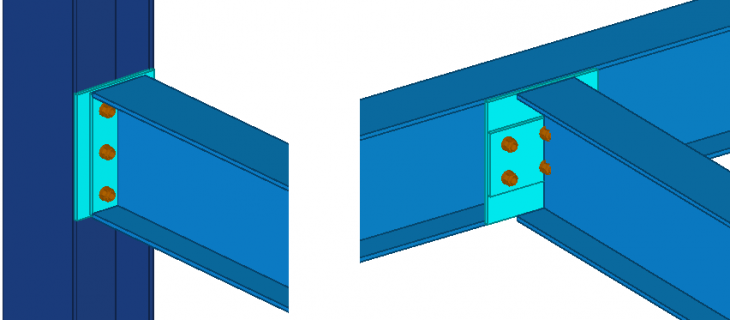
Tekla Structures includes system component Stiffened end plate (27). In Tekla Structures 2021, the default settings have been adjusted so that they now work correctly for a column-beam connection and a beam-beam connection:
Earlier Tekla Structures versions:
In addition, system component Stiffened end plate (27) includes new options for creating sink holes by using database file sinkholes.dat. For detailed information, see chapter New options for sink holes in system components.
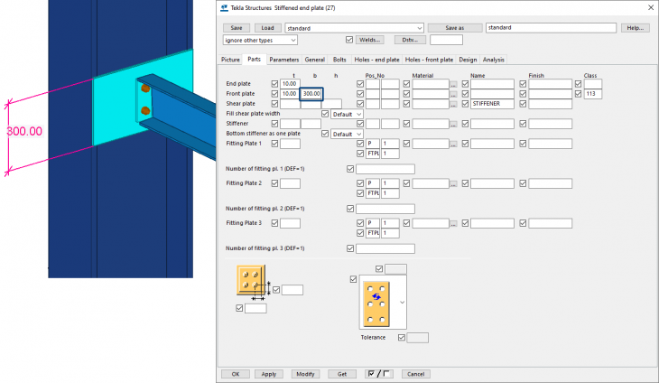
Also, the following has been adjusted in Tekla Structures 2021: When you rotate the secondary part (UNP in the image below), the height of the secondary plate is automatically adjusted to the height of the secondary part:
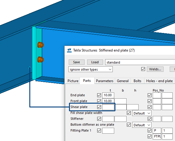
To adjust the height of the plate, enter a value in the field b on the tab Parts for the front plate:
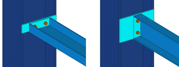
In addition, a stiffener was created in earlier Tekla Structures versions, if a value, for example, "10" was entered for the stiffener thickness, but also if no value was entered:
This has been changed and a stiffener is now only created in case a value has been entered for the stiffener thickness. If no value is entered, no stiffener is created:
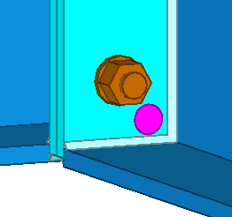
In Tekla Structures 2021 also the gap size for the end plate on the secondary beam has been fixed:
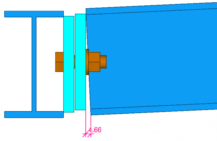
The gap size defines the limit value for the gap between the end plate and the secondary beam. Use this when the beam is slightly curved or sloped to decide if the end angle is so small that the beam end can be straight. If the actual gap is smaller than this value, the end of the beam is left straight. If the actual gap is larger than this value, the end of the beam is fitted to the end plate.
Also, a modification has been made to the command Create AutoConnections. In AutoConnection (and also AutoDefaults) is defined which component should be used in which situation. In Tekla Structures 2021, in AutoConnection system component Clip angle (141) has been replaced by system component Stiffened end plate (27).
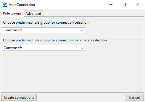
Click de following links for detailed information about the usage of commands AutoConnection and AutoDefaults.
Image
Earlier Tekla Structures versions:
Image
In addition, system component Stiffened end plate (27) includes new options for creating sink holes by using database file sinkholes.dat. For detailed information, see chapter New options for sink holes in system components.
Also, the following has been adjusted in Tekla Structures 2021: When you rotate the secondary part (UNP in the image below), the height of the secondary plate is automatically adjusted to the height of the secondary part:
Image
To adjust the height of the plate, enter a value in the field b on the tab Parts for the front plate:
Image
In addition, a stiffener was created in earlier Tekla Structures versions, if a value, for example, "10" was entered for the stiffener thickness, but also if no value was entered:
Image
This has been changed and a stiffener is now only created in case a value has been entered for the stiffener thickness. If no value is entered, no stiffener is created:
Image
In Tekla Structures 2021 also the gap size for the end plate on the secondary beam has been fixed:
Image
Image
The gap size defines the limit value for the gap between the end plate and the secondary beam. Use this when the beam is slightly curved or sloped to decide if the end angle is so small that the beam end can be straight. If the actual gap is smaller than this value, the end of the beam is left straight. If the actual gap is larger than this value, the end of the beam is fitted to the end plate.
Also, a modification has been made to the command Create AutoConnections. In AutoConnection (and also AutoDefaults) is defined which component should be used in which situation. In Tekla Structures 2021, in AutoConnection system component Clip angle (141) has been replaced by system component Stiffened end plate (27).
Image
Click de following links for detailed information about the usage of commands AutoConnection and AutoDefaults.
New options for sink holes in system components
The following system components now include a new option for using and defining sink holes by using data file sinkholes.dat:
● Joining plates (14)
● Column - 2 beam (14)
● Stiffened end plate (27)
● Seating cap 1 (37)
● Seating (39)
● Haunch (40)
● Cranked beam (41)
● Partial stiff end plate (65)
● Two sided end plate (142)
● End plate (144)
● Footplate (1029)
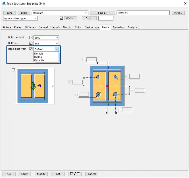
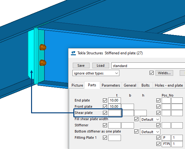
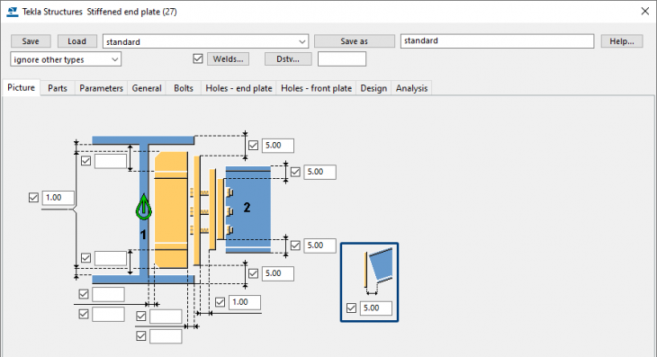
Some of these components, such as Stiffened end plate (27) now include the new tabs Holes - end plate and Holes - front plate to separately define the sink holes for the end plate and the front plate.
System components Joining plates (14), Stiffened end plate (27), Two sided end plate (142), End Plate (144) and Cranked beam (41) include supplied settings for which sink holes are defined, except for the setting standard.
These holes have been set in consultation with a number of customers, taking the welds into account so that they do not collide with the holes and to have enough space for the weld.
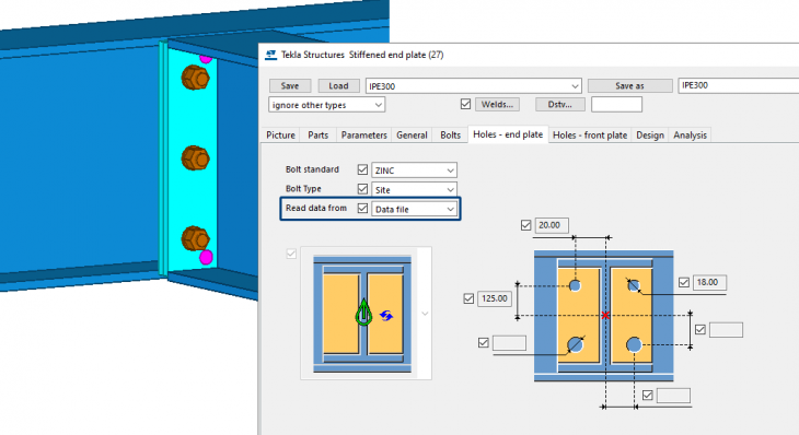
To apply sink holes, select the option Data file in the drop-down list. The corresponding values for the sink holes are displayed immediately. The values are grayed out because they are read from the sinkholes.dat data file:
This file is stored in the folder ..:\TeklaStructures\2021.0\Environments\ConstrusoftEuropean\General\profil:
How does this file work? First, in this file, the secondary profiles are defined per line (1) using wildcards, followed by the sinkhole option and the positions and diameters of the sinkholes. For example, secondary profile HE? 140 can be a HEA140 profile but also a HEB140 profile. When the corresponding setting is loaded in the system component, the sink hole positions (3) correspond to the values defined in the file sinkholes.dat:
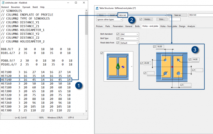
In the file you see the value 3 in the second column. This value refers to the sinkhole options in the drop-down list:
The following values in the lines are the horizontal distance, the vertical distance, and the hole diameter. The values are defined twice because 4 sink holes are created.
You can modify the data file sinkholes.dat as needed and save it in the folder ..:\TeklaStructures\2021.0\Environments\ConstrusoftEuropean\General\profil or in a folder defined by the advanced option
In addition to the data file sinkholes.dat, you can also select the option Default or Dialog from the drop-down list. Select one of the options in the drop-down list (1) so that you can change the entered values (the values you now see correspond to the values in the data file):
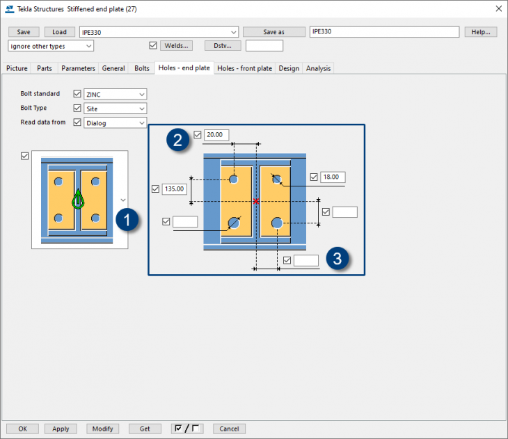
For example, when a beam is positioned skewed and you only want to adjust the position of the holes in the y direction, for example, the value of 125 mm becomes 135 mm.
As you can see in the image above, values are entered in three fields for the holes (2). For the three empty fields (3) counts the following: if nothing is entered, the entered value of (2) is the default for that empty field.
On the tab Holes - front plate, no values are defined for the sink holes because this plate not always includes sink holes. You can of course adjust/define this as needed.
● Joining plates (14)
● Column - 2 beam (14)
● Stiffened end plate (27)
● Seating cap 1 (37)
● Seating (39)
● Haunch (40)
● Cranked beam (41)
● Partial stiff end plate (65)
● Two sided end plate (142)
● End plate (144)
● Footplate (1029)
Image
Some of these components, such as Stiffened end plate (27) now include the new tabs Holes - end plate and Holes - front plate to separately define the sink holes for the end plate and the front plate.
Image
System components Joining plates (14), Stiffened end plate (27), Two sided end plate (142), End Plate (144) and Cranked beam (41) include supplied settings for which sink holes are defined, except for the setting standard.
These holes have been set in consultation with a number of customers, taking the welds into account so that they do not collide with the holes and to have enough space for the weld.
Image
|
Image
|
In case you have created settings for the above mentioned system components in earlier Tekla Structures versions, check these settings and update them if necessary and then save them again (after copying them to your TS folder in Tekla Structures 2021) so that they are up to date again in Tekla Structures 2021. |
To apply sink holes, select the option Data file in the drop-down list. The corresponding values for the sink holes are displayed immediately. The values are grayed out because they are read from the sinkholes.dat data file:
Image
This file is stored in the folder ..:\TeklaStructures\2021.0\Environments\ConstrusoftEuropean\General\profil:
How does this file work? First, in this file, the secondary profiles are defined per line (1) using wildcards, followed by the sinkhole option and the positions and diameters of the sinkholes. For example, secondary profile HE? 140 can be a HEA140 profile but also a HEB140 profile. When the corresponding setting is loaded in the system component, the sink hole positions (3) correspond to the values defined in the file sinkholes.dat:
Image
In the file you see the value 3 in the second column. This value refers to the sinkhole options in the drop-down list:
| Option | In the drop-down list |
|---|---|
| 1 |
Image
 |
| 2 |
Image
 |
| 3 |
Image
 |
The following values in the lines are the horizontal distance, the vertical distance, and the hole diameter. The values are defined twice because 4 sink holes are created.
You can modify the data file sinkholes.dat as needed and save it in the folder ..:\TeklaStructures\2021.0\Environments\ConstrusoftEuropean\General\profil or in a folder defined by the advanced option
XS_FIRM or XS_PROJECT.In addition to the data file sinkholes.dat, you can also select the option Default or Dialog from the drop-down list. Select one of the options in the drop-down list (1) so that you can change the entered values (the values you now see correspond to the values in the data file):
Image
For example, when a beam is positioned skewed and you only want to adjust the position of the holes in the y direction, for example, the value of 125 mm becomes 135 mm.
As you can see in the image above, values are entered in three fields for the holes (2). For the three empty fields (3) counts the following: if nothing is entered, the entered value of (2) is the default for that empty field.
On the tab Holes - front plate, no values are defined for the sink holes because this plate not always includes sink holes. You can of course adjust/define this as needed.
New online Help files available
The in Tekla Structures (by default) available system components Tensioner central gusset (18), CS Timber Roof Net Panel (m025) and CS Roof generator Net (m072) and the Tekla Warehouse tools Wooden roof (m150) and Detail numbering (m135) now include an (online) Help file:
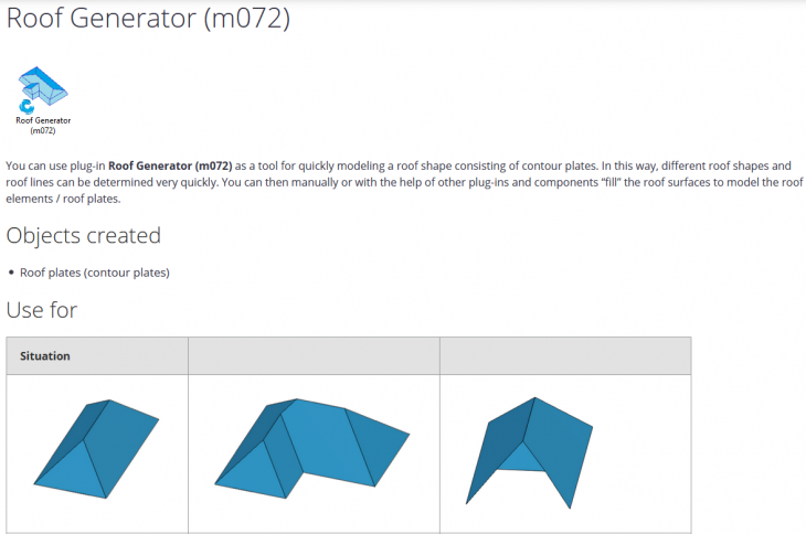
The Help files are located in the Tekla User Assistance and therefore online available. The main advantage of this is that if the system components have new functionalities, the Help files can be modified (updated) very quickly and are therefore immediately up to date (because they are online).
More and more Construsoft system component Help files will become available online in the future.
Image
Image
The Help files are located in the Tekla User Assistance and therefore online available. The main advantage of this is that if the system components have new functionalities, the Help files can be modified (updated) very quickly and are therefore immediately up to date (because they are online).
More and more Construsoft system component Help files will become available online in the future.
Wood wall (57)
System component Wood wall (57) for creating (prefab) timber walls, floor elements, metal stud frame structures, etc., now includes several improvements:
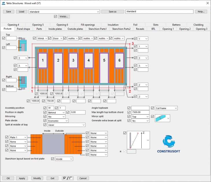
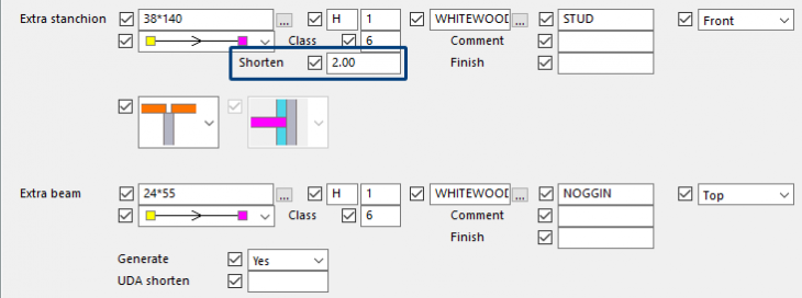
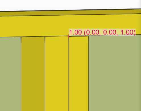
In case you are using an extra stanchion at the location of a seam in Tekla Structures 2021, the extra stanchion can be shortened with the new Shorten option on the tab Stanchion Parts2 where this value is distributed between the bottom and the top side of the extra stanchion:
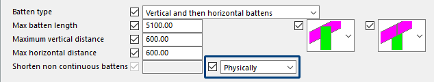
System component Wood wall (57) already included the option to indicate that battens needed to be shortened. This worked correctly for reports but not for the export to the machine control. For this, the battens have to be shortened physically. That is why you now have an extra option Physically.
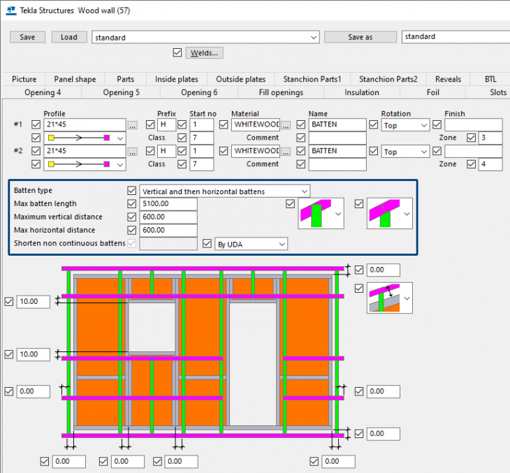
The “old” method By UDA:
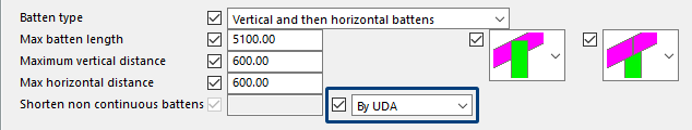
The new method Physically:
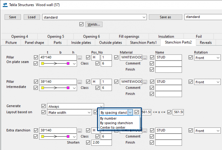
In addition to the already existing options By number and By spacing stanchion for the distribution of the stanchions, the option Center to center is added. This has the advantage that with different widths for the beams, this does not affect the distribution:
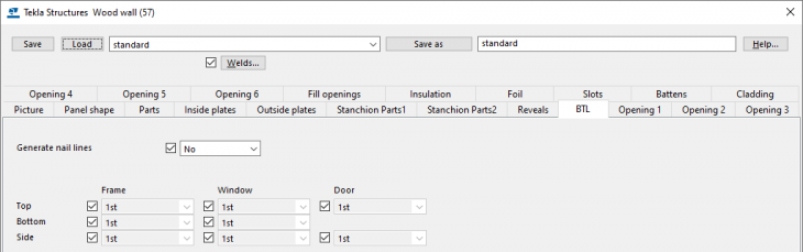
A BTL framing option was previously available on the BTL tab. This setting ensured that the element was not created as 1 whole element, but as 1 super element with various sub-elements. This working method could not be used if the element was exported as BTL for machine production, but also not for the default method of production drawings as supplied by Construsoft. Conclusion: Actually, this function should not be used, that is why it has been removed:
Earlier Tekla Structures versions:
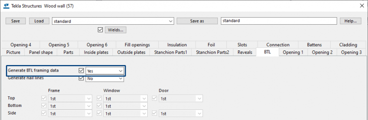
Tekla Structures 2021:
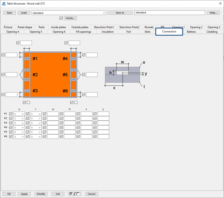
In addition, the functions that were available on the Connection tab were no longer used and therefore the tab has been removed:
A number of fixes have also been implemented:
● If a horizontal and a vertical batten were selected in the same layer, the intermediate battens must be shortened for ventilation purposes. This did not always work correctly and has now been fixed.
● Sometimes it was not the bottom batten that was the main part of the element, but the left stanchion. This has now been fixed.
● In some cases, the distances of the openings were not properly calculated. This has now been fixed.
● The distribution of the plates from the left sometimes resulted in an unexpected distribution of the plates. This has now been fixed.
Image
In case you are using an extra stanchion at the location of a seam in Tekla Structures 2021, the extra stanchion can be shortened with the new Shorten option on the tab Stanchion Parts2 where this value is distributed between the bottom and the top side of the extra stanchion:
Image
Image
System component Wood wall (57) already included the option to indicate that battens needed to be shortened. This worked correctly for reports but not for the export to the machine control. For this, the battens have to be shortened physically. That is why you now have an extra option Physically.
Image
The “old” method By UDA:
Image
The new method Physically:
Image
In addition to the already existing options By number and By spacing stanchion for the distribution of the stanchions, the option Center to center is added. This has the advantage that with different widths for the beams, this does not affect the distribution:
Image
A BTL framing option was previously available on the BTL tab. This setting ensured that the element was not created as 1 whole element, but as 1 super element with various sub-elements. This working method could not be used if the element was exported as BTL for machine production, but also not for the default method of production drawings as supplied by Construsoft. Conclusion: Actually, this function should not be used, that is why it has been removed:
Earlier Tekla Structures versions:
Image
Tekla Structures 2021:
Image
In addition, the functions that were available on the Connection tab were no longer used and therefore the tab has been removed:
Image
A number of fixes have also been implemented:
● If a horizontal and a vertical batten were selected in the same layer, the intermediate battens must be shortened for ventilation purposes. This did not always work correctly and has now been fixed.
● Sometimes it was not the bottom batten that was the main part of the element, but the left stanchion. This has now been fixed.
● In some cases, the distances of the openings were not properly calculated. This has now been fixed.
● The distribution of the plates from the left sometimes resulted in an unexpected distribution of the plates. This has now been fixed.
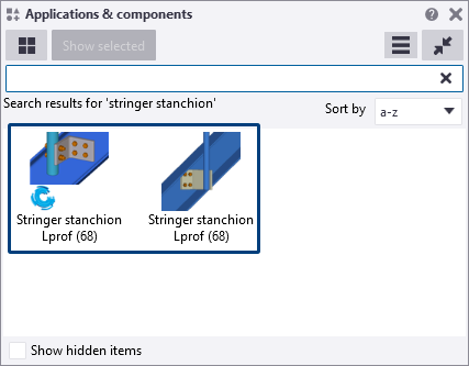
Stringer stanchion Lprof (68)
In earlier Tekla Structures versions, there were two system components Stringer stanchion Lprof (68) available to connect stanchions to the stringer:
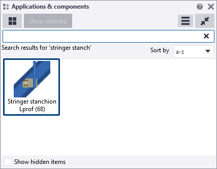
In Tekla Structures 2021, the Construsoft system component has been merged with the Tekla one so that the system component is available now only once in the Applications & components database:
Image
In Tekla Structures 2021, the Construsoft system component has been merged with the Tekla one so that the system component is available now only once in the Applications & components database:
Image
Rebar in beam (90) and Rebar in beam LT (90)
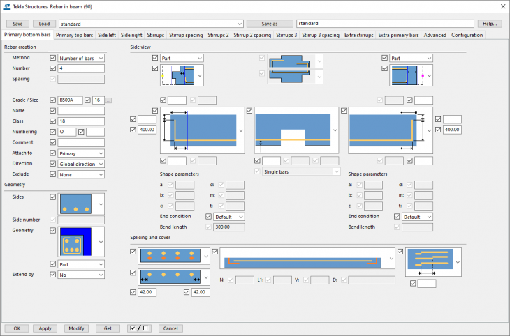
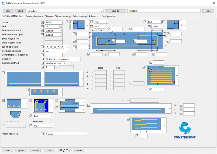
System components Rebar in beam (90) and Rebar in beam LT (91) include a new interface so that they are clearer and more structured and have a more logical layout.
Tekla Structures 2021:
Earlier Tekla Structures versions:
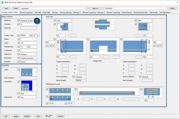
Now on all tabs, the parameters that belong together are now grouped together and can be found in the same place. The generation method (1) is shown in all tabs as the first option at the top left in the dialog box:
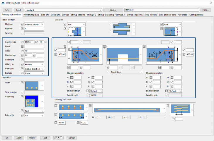
The images have also been adjusted (if necessary) so that the parameters associated with an image are now clearly visible and you can now define the bar properties on the tab itself for the relevant bars/stirrups (and no longer on the tab Advanced):
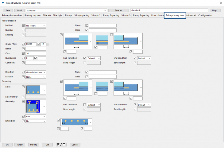
In addition, there is a new tab Extra primary bars available in which you can define additional primary bars:
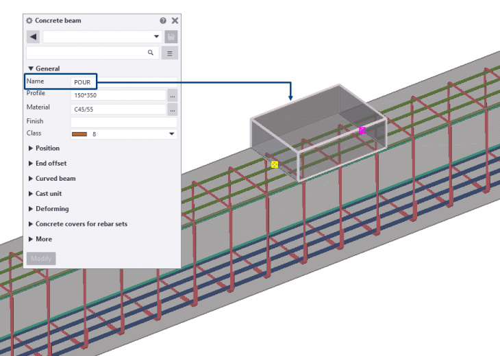
The extra bars are created at the location of a concrete part that you define based on the name or class of that part.
Suppose you have added a pour to a concrete beam with the name POUR:
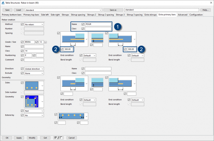
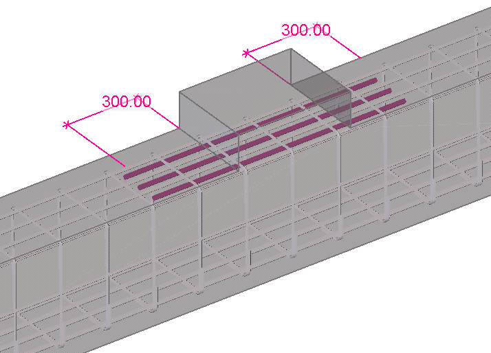
In the tab Extra primary bars, you can now define this name (1) and the properties (2) of the extra bars:
Tekla Structures 2021:
Image
Earlier Tekla Structures versions:
Image
Now on all tabs, the parameters that belong together are now grouped together and can be found in the same place. The generation method (1) is shown in all tabs as the first option at the top left in the dialog box:
Image
The images have also been adjusted (if necessary) so that the parameters associated with an image are now clearly visible and you can now define the bar properties on the tab itself for the relevant bars/stirrups (and no longer on the tab Advanced):
Image
In addition, there is a new tab Extra primary bars available in which you can define additional primary bars:
Image
The extra bars are created at the location of a concrete part that you define based on the name or class of that part.
Suppose you have added a pour to a concrete beam with the name POUR:
Image
In the tab Extra primary bars, you can now define this name (1) and the properties (2) of the extra bars:
Image
Image
Border rebar (92)
Tekla Structures includes system component Border rebar (92) for modeling border rebars in concrete parts. The generated reinforcement consists of edge bars and hairpins that are placed both on the edge of the element and around a recess.

In case you have created settings in previous Tekla Structures versions for system component Border rebar (92) and you load these settings in Tekla Structures 2021, you may see certain values in some fields, for example a diameter with decimals or the value -2147483648.000000:
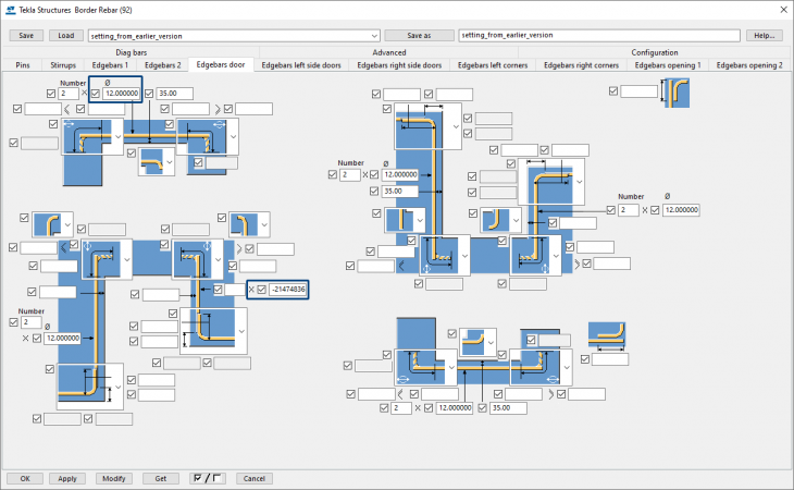
This is the result of a change that has been made to this component in Tekla Structures 2021.
The value -2147483648.000000 represents an empty field if nothing was entered for that field in the setting from a previous Tekla Structures version.
So, when you load settings from earlier Tekla Structures versions into Tekla Structures 2021, you must check all tabs per setting and adjust such values or clear the field. Next you save the new setting via the Save as button.
For detailed information about the usage the system component works, click the Help button in the system component's dialog box.
Image
In case you have created settings in previous Tekla Structures versions for system component Border rebar (92) and you load these settings in Tekla Structures 2021, you may see certain values in some fields, for example a diameter with decimals or the value -2147483648.000000:
Image
This is the result of a change that has been made to this component in Tekla Structures 2021.
The value -2147483648.000000 represents an empty field if nothing was entered for that field in the setting from a previous Tekla Structures version.
So, when you load settings from earlier Tekla Structures versions into Tekla Structures 2021, you must check all tabs per setting and adjust such values or clear the field. Next you save the new setting via the Save as button.
For detailed information about the usage the system component works, click the Help button in the system component's dialog box.
Changing options in (reinforcement) system components
Changing some options in particular reinforcement system components works differently from earlier Tekla Structures versions.
Sometimes you cannot immediately define and change the desired number. Sometimes you need to define a different diameter before you can apply the desired number.
Click here for a detailed video.
Sometimes you cannot immediately define and change the desired number. Sometimes you need to define a different diameter before you can apply the desired number.
Click here for a detailed video.
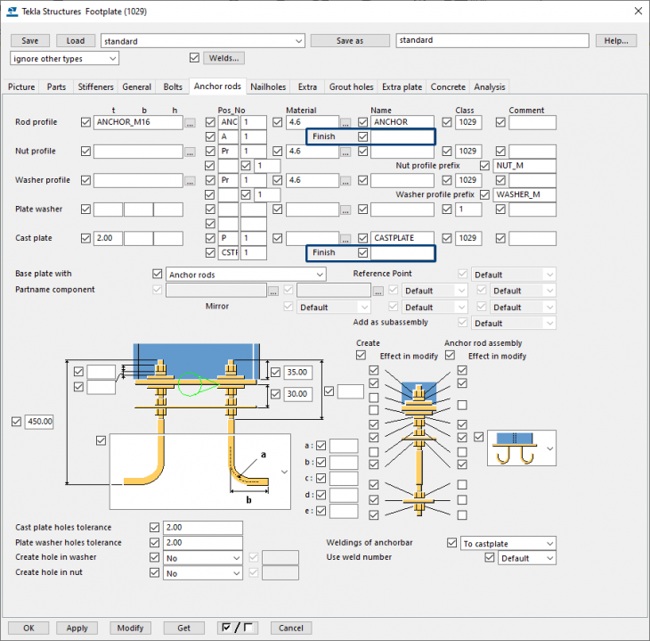
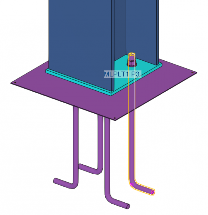
Footplate (1029)
In addition to the improvements made in earlier Tekla Structures versions, system component Footplate (1029) also includes several adjustments and improvements:
System component Footplate (1029) includes new options for creating sink holes by using database file sinkholes.dat. For detailed information, see chapter New options for sink holes in system components.
In earlier Tekla Structures versions, when using sinkholes, these sinkholes were also created in filler plates. This has now been fixed.
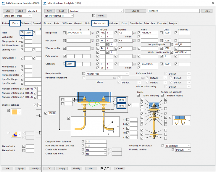
In addition, the tab Anchors now includes the new field Finish for the anchors and the cast plate:
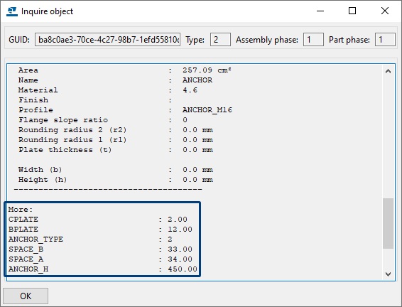
In addition, you now have the values CPLATE and BPLATE for the anchors, the cast plate and the base plate when you inquire the information of a part (Shift + I), for example from an anchor:
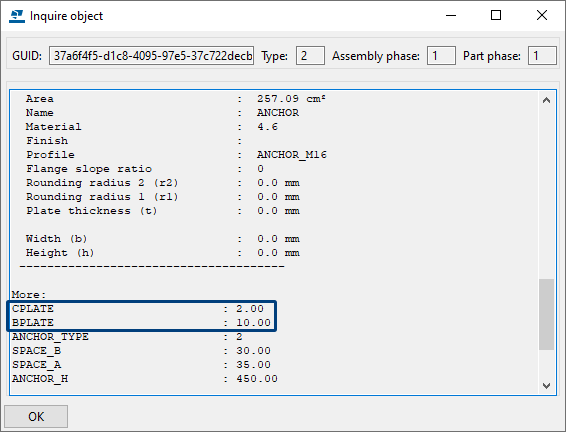
You can use these values in templates and reports to show the information.
In addition, you can use the values for calculating in formulas: in the anchor_list.doc list, for example, these values are used:
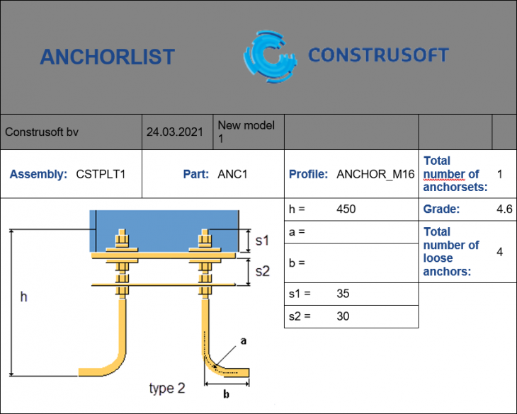
When you start calculating with the values and you have entered the following in the fields below:
...the values are shown when you inquire the information from an anchor:
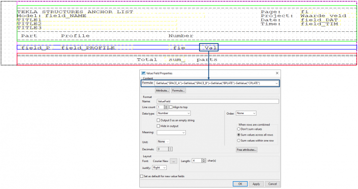
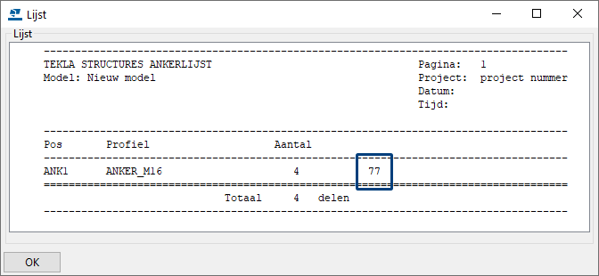
Next you can use the values, for example in the anchor list. You open the list in Template Editor and add a value field (or edit an existing value field), next use a formula:
Next when you generate the anchor list, the value (which is the result of the formula) is shown (34 + 33 + 12 - 2):
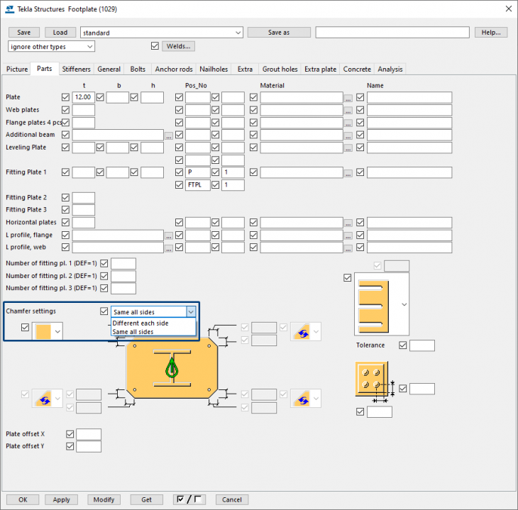
With regard to useability, the tab Parts now includes a new drop-down list for defining the chamfer settings of the base plate, one chamfer per corner or the same chamfer for all corners:
In earlier Tekla Structures version, in some cases the chamfer was not calculated correctly. This has now been fixed.
System component Footplate (1029) includes new options for creating sink holes by using database file sinkholes.dat. For detailed information, see chapter New options for sink holes in system components.
In earlier Tekla Structures versions, when using sinkholes, these sinkholes were also created in filler plates. This has now been fixed.
In addition, the tab Anchors now includes the new field Finish for the anchors and the cast plate:
Image
In addition, you now have the values CPLATE and BPLATE for the anchors, the cast plate and the base plate when you inquire the information of a part (Shift + I), for example from an anchor:
Image
You can use these values in templates and reports to show the information.
In addition, you can use the values for calculating in formulas: in the anchor_list.doc list, for example, these values are used:
Image
Image
When you start calculating with the values and you have entered the following in the fields below:
Image
...the values are shown when you inquire the information from an anchor:
Image
Image
Next you can use the values, for example in the anchor list. You open the list in Template Editor and add a value field (or edit an existing value field), next use a formula:
Image
Next when you generate the anchor list, the value (which is the result of the formula) is shown (34 + 33 + 12 - 2):
Image
With regard to useability, the tab Parts now includes a new drop-down list for defining the chamfer settings of the base plate, one chamfer per corner or the same chamfer for all corners:
Image
In earlier Tekla Structures version, in some cases the chamfer was not calculated correctly. This has now been fixed.
Custom components
Speed improvement for custom components
In Tekla Structures 2021 includes some speed improvements when applying custom components.
Mostly custom components that consist of many parts, such as custom components for railings, save a lot of time.
Mostly custom components that consist of many parts, such as custom components for railings, save a lot of time.
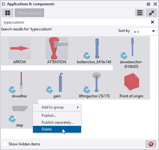
Delete custom components from the Applications & components database
In earlier Tekla Structures versions, deleting custom components from the Applications & component database sometimes did not work correctly. This is fixed in Tekla Structures 2021:
Image
Drawings
Modified template foils
Tekla Structures includes the template foils for several Tekla Structures versions to show the overlap per side of the foil in elements in the drawing:
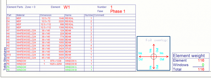
The template is stored in Tekla Structures 2021 in the folder ..:\TeklaStructures\2021.0\Environments\ConstrusoftEuropean\General\template.
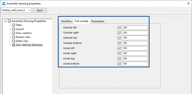
In earlier Tekla Structures versions, you defined the foil overlap in the assembly drawing user-defined attributes:
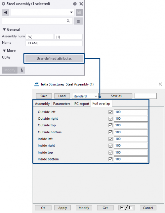
From Tekla Structures 2021 on, you can also define the overlap at the assembly level of the element in the model. To do this, do the following:
1. In toolbar Selecting, switch the button Select assemblies
 on.
on.
2. Double-click on the concerned assembly and next click the button User-defined attributes:
3. Define the foil overlap so that it is automatically displayed in the template foils in the drawing.
Image
The template is stored in Tekla Structures 2021 in the folder ..:\TeklaStructures\2021.0\Environments\ConstrusoftEuropean\General\template.
In earlier Tekla Structures versions, you defined the foil overlap in the assembly drawing user-defined attributes:
Image
From Tekla Structures 2021 on, you can also define the overlap at the assembly level of the element in the model. To do this, do the following:
1. In toolbar Selecting, switch the button Select assemblies
Image
2. Double-click on the concerned assembly and next click the button User-defined attributes:
Image
3. Define the foil overlap so that it is automatically displayed in the template foils in the drawing.
Copying drawing views in general arrangement drawings changed
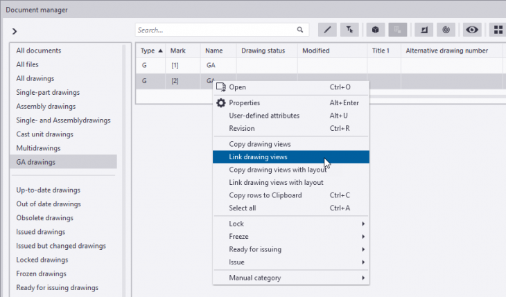
Tekla Structures includes the option to copy and to link drawing views from one general arrangement drawing to another.
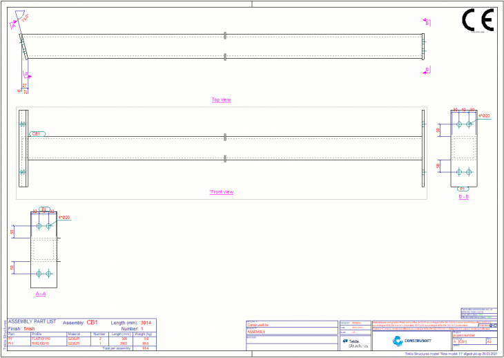
Link drawing views
When you link a view from general arrangement drawing G1 with general arrangement drawing G2:
... and general arrangement drawing G1 is modified, these changes are also made in general arrangement drawing G2.
If you delete general arrangement drawing G1 in the Documentmanager, the view in general arrangement drawing G2 is also deleted.
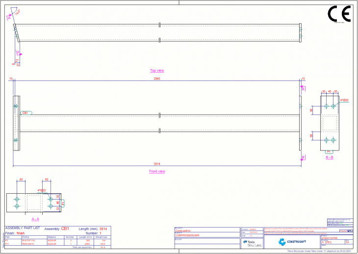
Copy drawing views
When you copy a view from general arrangement drawing G1 to general arrangement drawing G2:
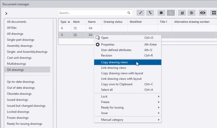
... and general arrangement drawing G1 is modified, these changes are not made in general arrangement drawing G2 because the copied view is not linked.
If you delete general arrangement drawing G1 in the Documentmanager, in Tekla Structures 2021 the view in general arrangement drawing G2 is not deleted. For this, the advanced option
In earlier Tekla Structures versions, the advanced option was set to
Link drawing views
When you link a view from general arrangement drawing G1 with general arrangement drawing G2:
Image
... and general arrangement drawing G1 is modified, these changes are also made in general arrangement drawing G2.
If you delete general arrangement drawing G1 in the Documentmanager, the view in general arrangement drawing G2 is also deleted.
Copy drawing views
When you copy a view from general arrangement drawing G1 to general arrangement drawing G2:
Image
... and general arrangement drawing G1 is modified, these changes are not made in general arrangement drawing G2 because the copied view is not linked.
If you delete general arrangement drawing G1 in the Documentmanager, in Tekla Structures 2021 the view in general arrangement drawing G2 is not deleted. For this, the advanced option
XS_CREATE_CONNECTION_WHEN_COPYING_DRAWING_VIEWS is set to FALSE.In earlier Tekla Structures versions, the advanced option was set to
TRUE which resulted in deleting the view in general arrangement drawing G2.Adjusted rotation section views in drawings
Tekla Structures includes the advanced option
The advanced option has been changed in Tekla Structures 2021 and is now set to
Defines the rotation of a section by the orientation of the view whose section symbol of the section is located:
In earlier Tekla Structures versions, the advanced option was set to
The rotation of all section views is the same as the orientation of the main view:
XS_ROTATE_CUT_VIEWS (via File > Settings > Advanced options category Drawing View) to specify the rotation of section views. This only applies to section views that Tekla Structures creates automatically. Manually created views have the same rotation as the view they are created from.The advanced option has been changed in Tekla Structures 2021 and is now set to
BY_SYMBOL_MAIN_VIEW:Image
Defines the rotation of a section by the orientation of the view whose section symbol of the section is located:
In earlier Tekla Structures versions, the advanced option was set to
BY_MAIN_VIEW by default.The rotation of all section views is the same as the orientation of the main view:
Image
Improved dimension rule associativity
Tekla Structures includes associativity for dimensions since several versions:
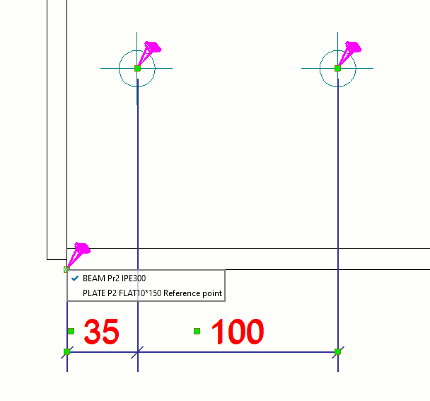
Each dimension point associativity symbol includes a list of objects with available associative locations. As you can see in the image above, you can link the dimension point to the beam or to the welded plate.
It may happen that the locations of the dimension points are unclear, for example in a sandwich panel where there may be several objects in the same point location:
In earlier Tekla Structures versions, dimension points were associated by default with the objects that the dimension points were added to when you manually dimensioned.
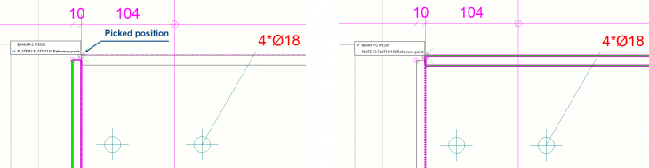
From Tekla Structures 2021 onwards, you can select an associativity rule for each dimension point during the manual dimensioning of the drawing objects. Now you can properly associate a dimension during its creation, and the dimension locations are preserved better during drawing updates and cloning.
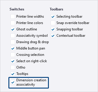
To activate the new dimension creation associativity functionality, go to File > Settings in the drawing mode, and in the Switches section, select the Dimension creation associativity check box.
Next start creating a dimension. Pick the dimension point position, and the associativity rules list is displayed each time when a point with available associativity rules is detected.
In the example below, the dimension point can now be linked to the plate or to the beam:
Image
Each dimension point associativity symbol includes a list of objects with available associative locations. As you can see in the image above, you can link the dimension point to the beam or to the welded plate.
It may happen that the locations of the dimension points are unclear, for example in a sandwich panel where there may be several objects in the same point location:
Image
In earlier Tekla Structures versions, dimension points were associated by default with the objects that the dimension points were added to when you manually dimensioned.
From Tekla Structures 2021 onwards, you can select an associativity rule for each dimension point during the manual dimensioning of the drawing objects. Now you can properly associate a dimension during its creation, and the dimension locations are preserved better during drawing updates and cloning.
To activate the new dimension creation associativity functionality, go to File > Settings in the drawing mode, and in the Switches section, select the Dimension creation associativity check box.
Image
Next start creating a dimension. Pick the dimension point position, and the associativity rules list is displayed each time when a point with available associativity rules is detected.
In the example below, the dimension point can now be linked to the plate or to the beam:
Image
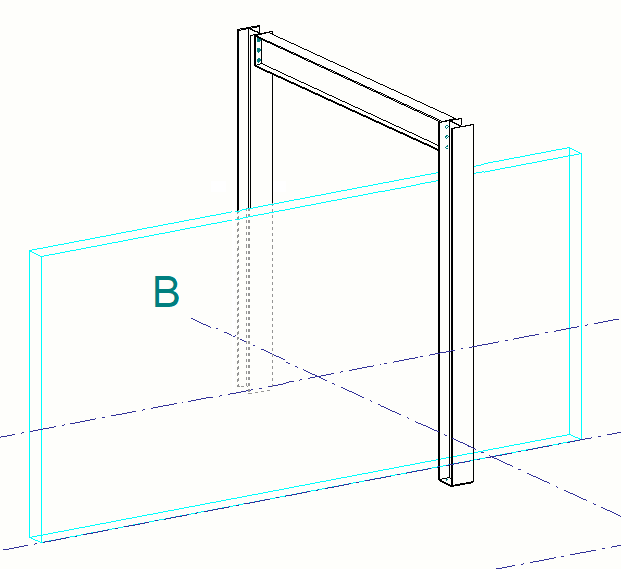
Adjusted representation for reference models in drawings
You can represent reference models in drawings by using the options Outline or Wireframe:
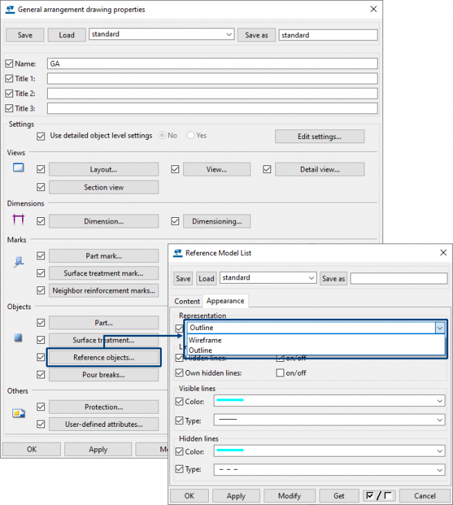
In earlier Tekla Structures versions, the hidden lines of model objects were not turned off correctly or represented as dotted lines behind reference models in case the setting Outline was applied. The following example shows a structure consisting of Tekla Structures model objects and a wall as a reference model:
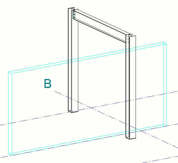
This has been solved in Tekla Structures 2021 and the hidden lines of model objects are correctly turned off or represented as dotted lines behind reference models.
The hidden lines are turned off:
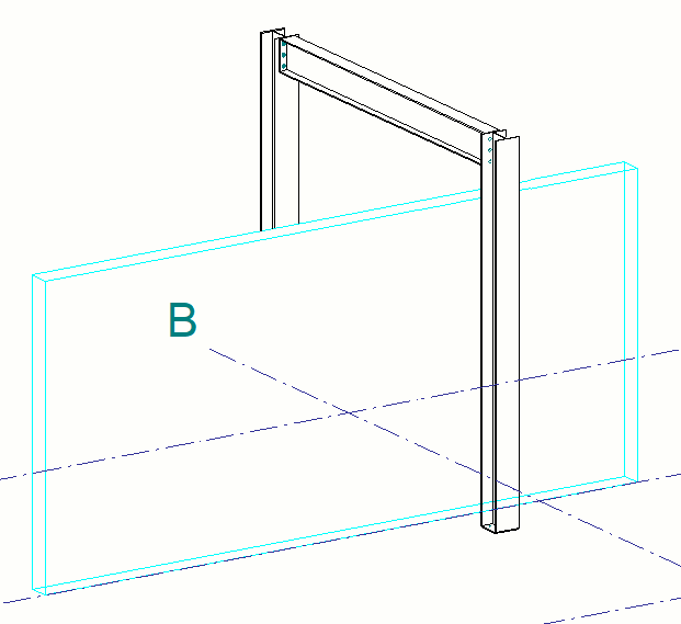
The hidden lines are dotted:
Image
In earlier Tekla Structures versions, the hidden lines of model objects were not turned off correctly or represented as dotted lines behind reference models in case the setting Outline was applied. The following example shows a structure consisting of Tekla Structures model objects and a wall as a reference model:
Image
This has been solved in Tekla Structures 2021 and the hidden lines of model objects are correctly turned off or represented as dotted lines behind reference models.
The hidden lines are turned off:
Image
The hidden lines are dotted:
Image
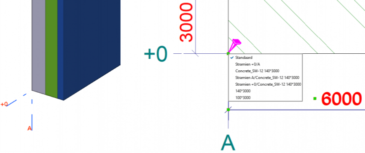
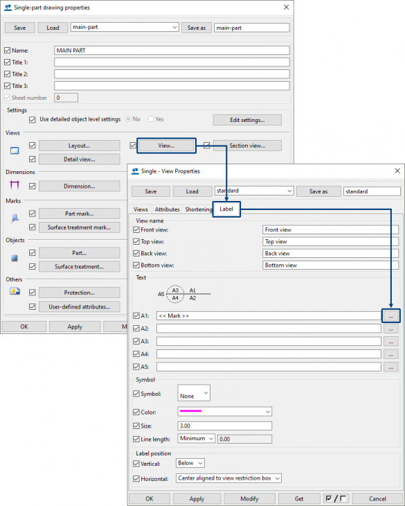
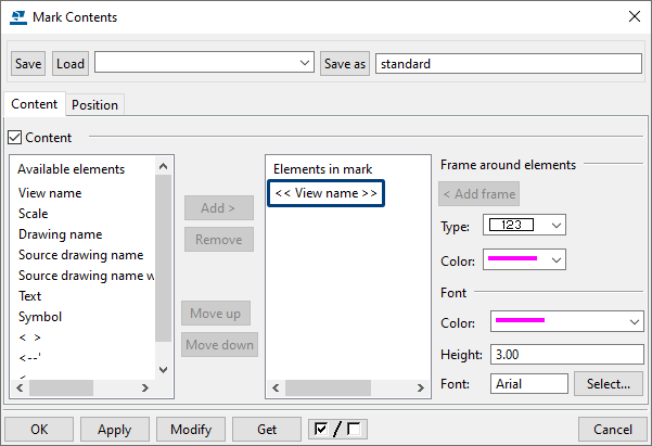
Representation view labels in single part drawings for parts
Now view labels are represented by default in single part drawings for parts:
For this, the option in the Mark contents dialog box is set in the single-part drawing properties dialog box:
If desired, you can adjust the content of this label content.
Image
For this, the option in the Mark contents dialog box is set in the single-part drawing properties dialog box:
Image
Image
If desired, you can adjust the content of this label content.
Location of images in templates changed
The location of the images used in templates in drawings has been changed so that the environment ConstrusoftEuropean is complete after installation. The files are now stored in the folder:
..:\TeklaStructures\2021.0\Environments\ConstrusoftEuropean\General\template\bitmaps
In earlier Tekla Structures versions, the images were stored in the folder:
..:\TeklaStructures\<version>\nt\bin\TplEd\bitmaps
..:\TeklaStructures\2021.0\Environments\ConstrusoftEuropean\General\template\bitmaps
In earlier Tekla Structures versions, the images were stored in the folder:
..:\TeklaStructures\<version>\nt\bin\TplEd\bitmaps
Adjusted rebar dimensioning marks
Since Tekla Structures 2020 you can use the command Rebar in the ribbon for creating various types of rebar dimension marks:
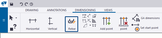
This command is also available in the context menu and via the function Quick launch.
The properties dialog box of the Rebar command includes various settings for the dimension marks by default:
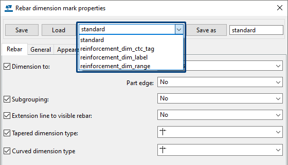
See the Tekla Structures 2020 Release Info for detailed information about these settings (chapter Drawings > Single command for creating various types of rebar dimension marks).
These settings have all been adjusted so that the placing is now set to Fixed:
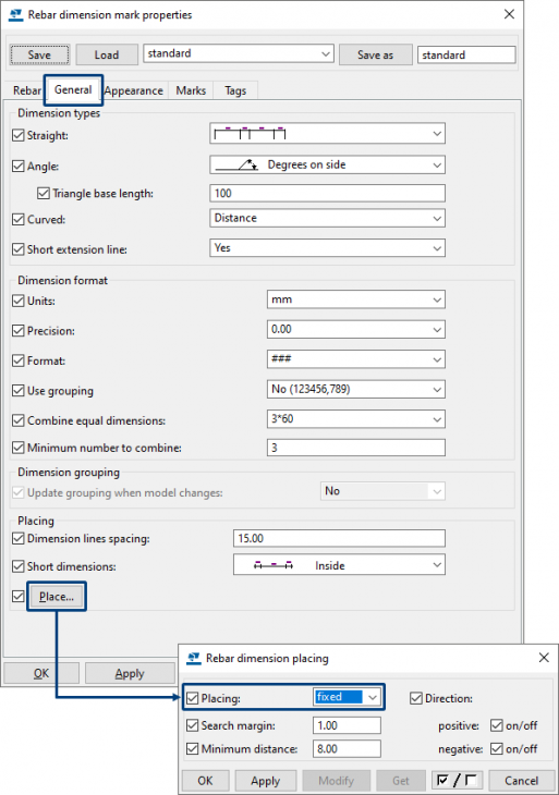
This allows you to pick the location by yourself when creating the dimension line.
In earlier Tekla Structures versions, the location of the dimension line is determined automatically because the placing was set to free.
Click here for detailed information about rebar dimensioning improvements.
Image
This command is also available in the context menu and via the function Quick launch.
The properties dialog box of the Rebar command includes various settings for the dimension marks by default:
Image
See the Tekla Structures 2020 Release Info for detailed information about these settings (chapter Drawings > Single command for creating various types of rebar dimension marks).
These settings have all been adjusted so that the placing is now set to Fixed:
Image
This allows you to pick the location by yourself when creating the dimension line.
In earlier Tekla Structures versions, the location of the dimension line is determined automatically because the placing was set to free.
Click here for detailed information about rebar dimensioning improvements.
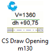
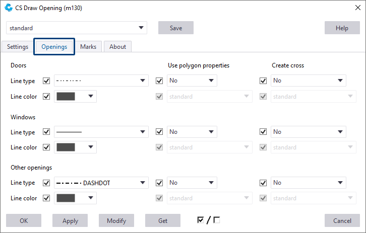
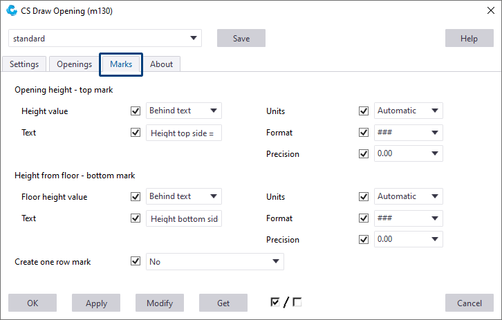
New tool CS Draw Opening (m130)
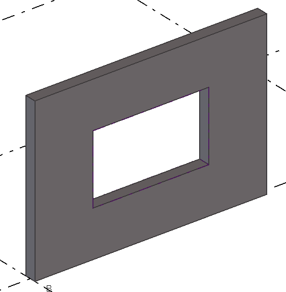
You can now use the new tool CS Draw Opening (m130) to mark and label openings in drawings:
In the Tekla Structures model:
In the drawing:
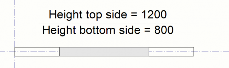
In the Openings tab, you can set the appearance for the different types of openings (which Tekla Structures automatically recognizes):
In the Marks tab you can define the contents for the marks:
Image
In the Tekla Structures model:
Image
In the drawing:
Image
In the Openings tab, you can set the appearance for the different types of openings (which Tekla Structures automatically recognizes):
Image
In the Marks tab you can define the contents for the marks:
Image
Tools/plug-ins
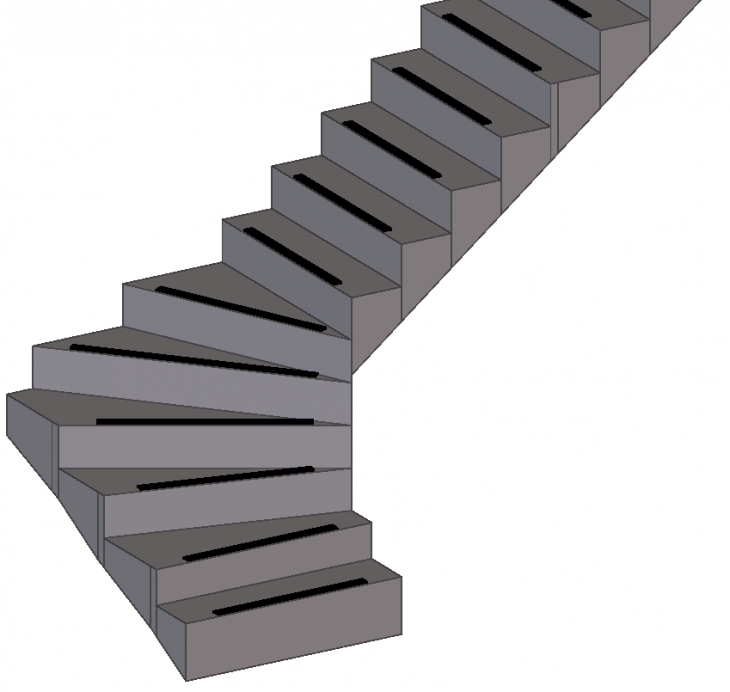
Spiral concrete stairs (m006)
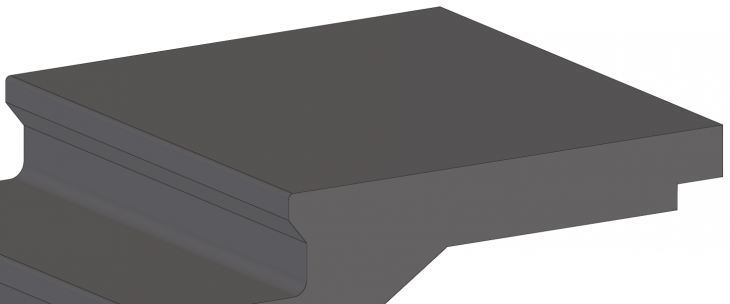
Tekla Structures includes plug-in Spiral concrete stairs (m006) for modeling spiral concrete stairs:
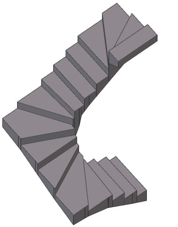
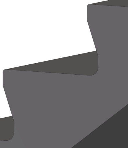
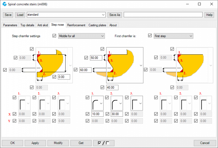
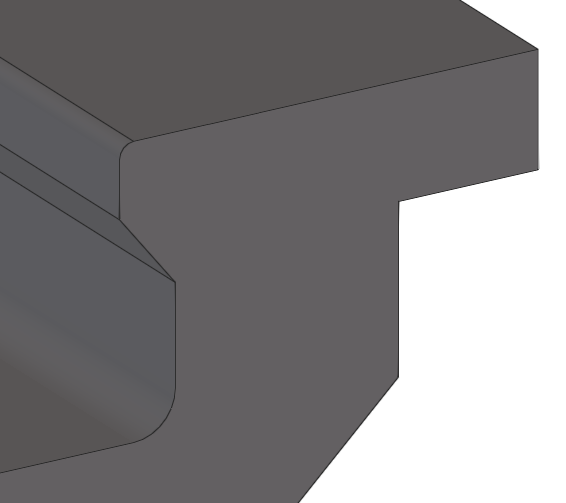
On the tab Step nose, you now have various options to define the details of the step:
The new tab Top details offers the possibility to define the detail at the top of the stairs, for example a recess for a support. In addition, it is possible to define a landing:
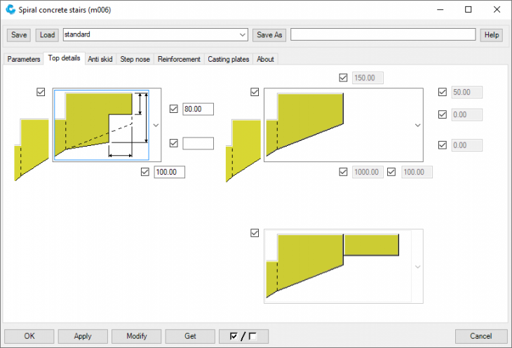
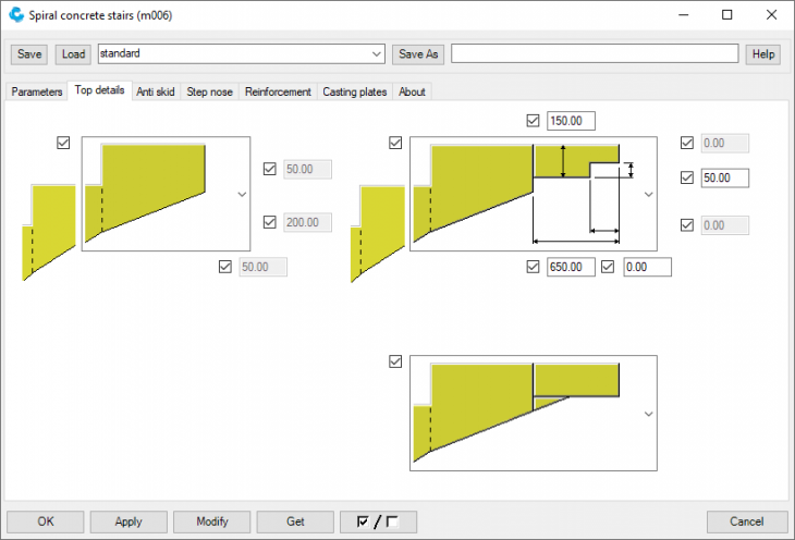
For detailed information, click the Help button in the plug-in.
Image
Image
Image
On the tab Step nose, you now have various options to define the details of the step:
Image
Image
The new tab Top details offers the possibility to define the detail at the top of the stairs, for example a recess for a support. In addition, it is possible to define a landing:
Image
Image
Image
Image
For detailed information, click the Help button in the plug-in.
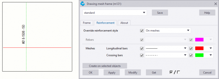
Drawing mesh frame (m121)
Tekla Structures includes the tool Drawing mesh frame (m121):
You use the tool to create outlines for reinforcement groups.

You can also customize the appearance of the reinforcement groups, for example of a reinforcement mesh the longitudinal and the crossing bars in a separate color:
Image
You use the tool to create outlines for reinforcement groups.
Image
You can also customize the appearance of the reinforcement groups, for example of a reinforcement mesh the longitudinal and the crossing bars in a separate color:
Image
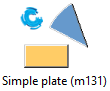
Simple plate (m131)
Tekla Structures now includes the new tool Simple plate (m131) to quickly and easily model contour plates:
For optimal use of the tool, make sure that the command Direct modification
 (shortcut D) is enabled.
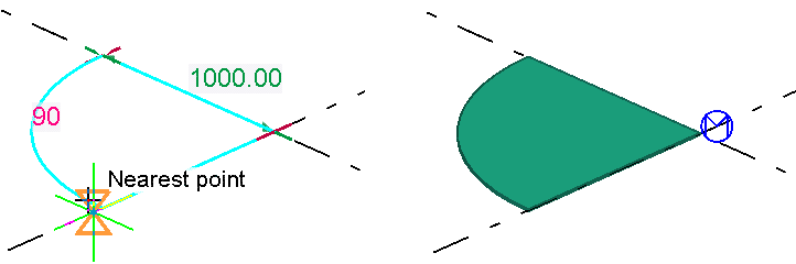
You can model a contour plate by picking 2 or 3 points.
2 points: You pick the first and the second point:
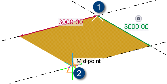
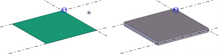
Steel plate Concrete plate
3 points: Select the tool in the Applications & components database by clicking it once (1), move to the Contextual toolbar symbol
 so that the Contextual toolbar appears (2):
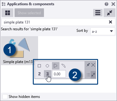
Now select the option 3 points and the shape of the plate and pick the points in the Tekla Structures model:
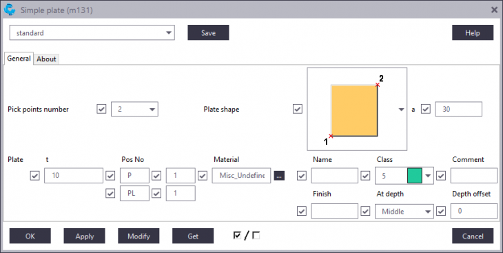
Once the plate has been modeled, you can adjust the plate properties in the following ways:
● By clicking on the symbol of the tool once, the following dialog box appears:
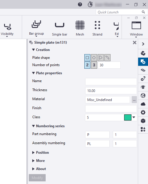
You can now adjust the shape of the plate and the other properties.
● By double-clicking on the tool's icon
 , the properties dialog box appears:
● Via the Contextual toolbar (short key Ctrl + K):
Image
For optimal use of the tool, make sure that the command Direct modification
Image
You can model a contour plate by picking 2 or 3 points.
2 points: You pick the first and the second point:
Image
Image
Steel plate Concrete plate
3 points: Select the tool in the Applications & components database by clicking it once (1), move to the Contextual toolbar symbol
Image
Image
Now select the option 3 points and the shape of the plate and pick the points in the Tekla Structures model:
Image
Once the plate has been modeled, you can adjust the plate properties in the following ways:
● By clicking on the symbol of the tool once, the following dialog box appears:
Image
You can now adjust the shape of the plate and the other properties.
● By double-clicking on the tool's icon
Image
Image
● Via the Contextual toolbar (short key Ctrl + K):
Image
Tekla Warehouse
Wiscon export
The tool Wiscon export was included in Tekla Structures by default in earlier Tekla Structures versions. The tool has been moved to Tekla Warehouse and is therefore no longer available in Tekla Structures.
Image
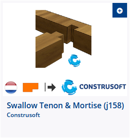
New and adjusted tools in Tekla Warehouse
Several new tools are available in Tekla Warehouse such as Detail numbering (m135) for quickly marking and numbering detail positions and also for creating detail drawings of that position and Swallow Tenon & Mortise (j158) to create a swallow tale connection between 2 beams , whether they do have an angle or not:
Besides several tools are improved such as Reporting (ML112) for generating advanced saw reports of the tool BVX Export (ML027) for exporting to BVX files (production data for Wood framing machines):
These and other tools are frequently updated, for example because they have new functionalities or because they contain various improvements and fixes.
Set an alert
You can set an alert in Tekla Warehouse for the tools to get informed automatically in case the content changes:
Image
Image
Besides several tools are improved such as Reporting (ML112) for generating advanced saw reports of the tool BVX Export (ML027) for exporting to BVX files (production data for Wood framing machines):
Image
Image
These and other tools are frequently updated, for example because they have new functionalities or because they contain various improvements and fixes.
Set an alert
You can set an alert in Tekla Warehouse for the tools to get informed automatically in case the content changes:
Image
Issue tool
You can use the Issue tool in Tekla Structures. The tool is available in Tekla Warehouse:
The tool automatically create issues of the model and revision tasks:
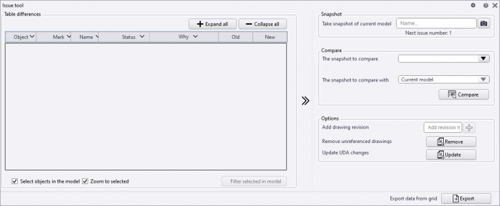
The tool supports different types of objects, and you can export the results to Excel or CSV.
See the tab Details in Tekla Warehouse for a video showing how to use this tool.
Image
The tool automatically create issues of the model and revision tasks:
Image
Image
The tool supports different types of objects, and you can export the results to Excel or CSV.
See the tab Details in Tekla Warehouse for a video showing how to use this tool.