Grasshopper - Tekla Structural Designer Live Link (GH-TSD)
2024
Tekla Structural Designer
2023
Tekla Structural Designer
2022
Tekla Structural Designer
2021
Tekla Structural Designer
2020
Tekla Structural Designer
Environment
Eurocode
USA
Image

Introduction
The Grasshopper-Tekla Structural Designer (GH-TSD) live link enables algorithmic modelling, parametric design exploration, and data driven design for Tekla Structural Designer (TSD) using Rhino/Grasshopper.
The link is a set of Grasshopper components that can create and update objects live in TSD. The link also provides the capability to automate TSD static analysis & record global displacement results using Grasshopper.
Prerequisites
You need to have Rhino (download) and Tekla Structural Designer (version 2020 or later) installed on the same machine. There are specific versions of the GH-TSD plugin for each major TSD release & each service pack.
Grasshopper is included in the Rhino 6 install. If you're using Rhino 5, you need to install Grasshopper separately (download).
You can try out the full version of Rhino for free for 90 days. The Grasshopper add-on is free of charge.
Setup
If you've already installed any version of the link and are doing an update or re-install, see the update section further down.
- Download the zip with the required files from Tekla Warehouse (download).
- Make sure you download a package targeting the (installed) version of Tekla Structural Designer you'd like to work with.
- Run Tekla Structural Designer and create a new document.
- Run Grasshopper and drag GH-TSD.gha onto the canvas to install the components. A new component tab labeled TSD [version] should appear.
- If the TSD tab doesn’t show up, the component file might be blocked as it’s downloaded from the internet. To unblock the file:
- In Grasshopper, click File > Special Folders > Components Folder
- Right-click GH-TSD.gha and click Properties
- Under the General tab, click on the Unblock button, and click OK. (If you don’t see an Unblock button, the file is not blocked.)
- Restart Rhino/Grasshopper. The TSD tab should now be visible in Grasshopper.
- If the TSD tab doesn’t show up, the component file might be blocked as it’s downloaded from the internet. To unblock the file:
To update, re-install or install components for another Tekla Structural Designer version:
- In Grasshopper, click File > Special Folders > Components Folder
- Close Grasshopper and Rhino, and replace the GH-TSD.gha in the Components Folder with the new file
- Launch Grasshopper again
- If the TSD tab doesn't show up, you need to unblock it as described in the previous section
Once Installed, take a look at the Working with the link section of this article to start working with Grasshopper.
1. Working with the link
1.1 Getting started - example files
Once the GH-TSD link is installed, you are ready to try the example files.
For best results, TSD should be started before Grasshopper.
Starting with both TSD & Grasshopper closed:
For best results, TSD should be started before Grasshopper.
Starting with both TSD & Grasshopper closed:
- Run TSD (version 2020 or later) and create a new document
- Run Rhino (64-bit)
- Run Grasshopper
You are now ready to run the first example file.
1.2 Getting started - creating a model
- In the folder for your headcode/region (EC or US), open one of the Concrete_MultiStorey files, and ensure the units in Rhino match those of the example file:
- EC: metres or millimetres
- US: inches or millimetres
- Locate the model component (blue circle) and link it to TSD, by right-clicking on the black part of the component:
Image

- TSD will display preview graphics while the model is exported from Grasshopper:
Image

- TSD will update the model after the last export from Grasshopper.
- In TSD, switch to the Grasshopper loadcase to see the loads that have been exported from Grasshopper:
Image

- You can now add & connect other components, or change the input parameters, and see those changes reflected live in TSD.
- TSD will display preview graphics while the model is exported from Grasshopper:
1.3 Getting started - running an analysis and collecting results
- In the folder for your headcode/region (EC or US), open one of the Steel_Truss files, and ensure the units in Rhino match those of the example file:
- EC: metres or millimetres
- US: inches or millimetres
- Locate the model component (blue circle) and link it to TSD, by right-clicking on the black part of the component
- The model will be exported to TSD and updated
- Connect the model component loading output to the analysis component loading input:
Image

- The analysis will complete. In TSD, progress can be seen in the process window. In TSD, switch to the results view and look at the deflections for the combination:
Image

- Connect the combination component to the Global Nodal Displacements component loading input:
Image

- The maximum and minimum displacements (also seen in the TSD results view) will be available in Grasshopper:
Image

1.4 General notes
- Make sure you run TSD and open a (new) document before running Rhino/Grasshopper or inserting components. Components will show warnings when TSD cannot be reached.
- The TSD components convert native Rhino/Grasshopper Geometry objects such as lines & polylines to structural objects such as beams, columns and walls in TSD. It is good modelling practice to get your script producing a suitable configuration in Grasshopper, before adding and connecting TSD components.
- To export the TSD objects created by individual components, they must be linked to a Model Component. Only one Model Component may be active at any one time.
- Removing components from the canvas, removing their inputs, or disconnecting them from the model component removes the generated objects from the TSD document.
- If there are multiple (compatible) instances of TSD running, the GH-TSD link will create geometry in the instance that was opened first.
- It is best practice to work with only one running instance of TSD, only one running instance of Grasshopper, and a single Grasshopper script. If switching between multiple scripts containing TSD components, refresh the TSD model by disabling and re-enabling the Model Component.
- The link uses the units of the currently open Rhino Document for the geometrical inputs.
- The link uses the units of the currently open TSD Document for all other inputs (Force, Area, Inertia etc.)
- The link uses specific data from the currently open TSD Document, such as section sizes and material grades.
1.5 Advanced topics
Setting option parameters
Many TSD components have parameters which are not of the basic Grasshopper types, e.g. strings, numbers, bools.
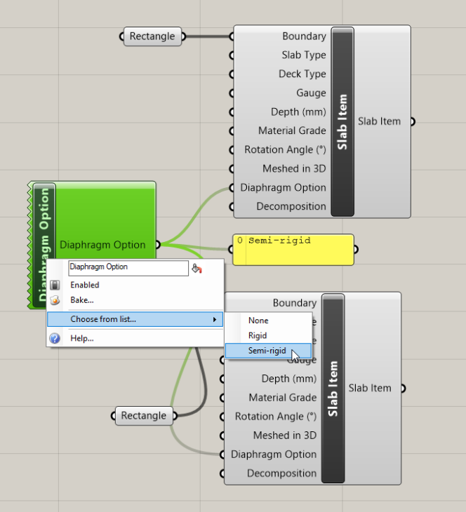
For example, the Slab Item component has an input parameter for Diaphragm Option:

There are a number of ways that you as a user can specify such option parameters. The simplest is to set the value directly on the component, by right-clicking the parameter and choosing from the provided list:

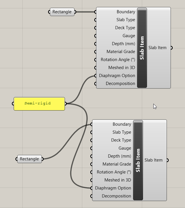
Alternatively, there are a number of option components included with the GH-TSD link:

These allow you to specify a single value for each option, which can then be used on multiple components:
The final alternative is to define such options using a text panel. The provided text must match the name of the option exactly:
For example, the Slab Item component has an input parameter for Diaphragm Option:
Image
There are a number of ways that you as a user can specify such option parameters. The simplest is to set the value directly on the component, by right-clicking the parameter and choosing from the provided list:
Image
Alternatively, there are a number of option components included with the GH-TSD link:
Image
These allow you to specify a single value for each option, which can then be used on multiple components:
Image
The final alternative is to define such options using a text panel. The provided text must match the name of the option exactly:
Image
Continuing sessions
The GH-TSD link allows you to parametrically create objects in TSD from Grasshopper, save both files, reopen those files at a later time, and continue working with the parametric link.
To do this:
To do this:
- Finish your modelling in Grasshopper and allow TSD to finish updating the model
- Save the Grasshopper model
- Save the TSD model
When you want to continue your workflow:
- Run TSD
- Open the TSD model
- Run Grasshopper
- Open the Grasshopper script
- Enable the model component
At this point, changes made in your Grasshopper script should be reflected in TSD as updates of the existing model, rather than as creation of new objects.
This approach can be particularly useful if you want to model some non-parametric objects directly in TSD, or want to create unsupported objects, e.g. envelopes, and have those persist between sessions.
Opening Grasshopper Scripts saved with the 2019i versions of the plugin
Grasshopper scripts saved in GH-TSD 2019i are compatible with GH-TSD 2020. However, upon opening a script saved in GH-TSD 2019i, it is necessary to add a Model Component, and perform a first time export of TSD objects from Grasshopper to TSD.
1.6 Troubleshooting
TSD Status in Grasshopper
The TSD status banner in Grasshopper indicates whether Grasshopper can ‘see’ TSD:
Image

When TSD is busy completing a process, the banner will indicate which process is completing:
Image

If Grasshopper cannot ‘see’ TSD, the banner will highlight this in red:
Image

Should you see this, check that a compatible version of TSD is running, and was started before starting Grasshopper. Warning messages will also show on components, as detailed in the following section.
The status banner can be hidden by navigating (in Grasshopper) to the menu: Display >> Canvas Widgets >> TSD Status.
Warning messages on components
If TSD cannot be reached, the GH-TSD link will add warning bubbles to TSD components:


Should you see these messages, check that:
Image
Image
Should you see these messages, check that:
- A compatible version of TSD is running, and was started before starting Grasshopper
- There is a document in TSD
Resolving instances where TSD does not respond to changes in Grasshopper
Should you find that TSD does not respond to a change you have made in Grasshopper, and warnings are not visible on components, try the following operations (in order):
- Recompute the solution. Right-click the Grasshopper canvas and select recompute
- Disconnect a TSD component from its input geometry, and reconnect it
- Disable and re-enable the model component
- Delete the model component and add it again
- Close the Grasshopper document (Ctrl+W) and reopen it
- This is required if you have changed any model settings in TSD, such as units, headcode or region.
- Restart Rhino & Grasshopper
- This is required to reset default parameter values on components, e.g. Steel Grade
2. Components in the GH-TSD link
2.1 Geometry Components
Image

Steel components
- Steel Beam
Image

- Creates a single-span steel beam along the provided line
- Steel Column
Image

- Creates a steel column along the provided line. The column in TSD is automatically split into stacks between levels (levels are added automatically in TSD for Slab Items created from Grasshopper). The column line provided in Grasshopper should represent the whole column including all stacks.
- Steel Brace
Image

- Creates a steel brace along the provided line
Concrete components
- Concrete Beam
Image

- Creates a single-span concrete beam along the provided line
- Concrete Column
Image

- Creates a concrete column along the provided line. The column in TSD is automatically split into stacks between levels (levels are added automatically in TSD for Slab Items created from Grasshopper). The column line provided in Grasshopper should represent the whole column including all stacks.
- Concrete Wall
Image

- Creates a concrete wall with the provided boundary (curve). The wall in TSD is automatically split into panels based on incoming geometry such as members and slabs. The wall boundary should represent the whole wall including all panels. The input curve must be a valid, planar, non-horizontal polyline with 4 segments.
Panel components
- Slab Item
Image

- Creates a Slab Item with the provided boundary (curve). The input curve must be a valid, planar polyline with at least 3 segments.
- Roof Panel
Image

- Creates a Roof Panel with the provided boundary (curve). The input curve must be a valid, planar polyline with at least 3 segments.
- Wall Panel
Image

- Creates a Wall Panel with the provided boundary (curve). The input curve must be a valid, planar polyline with at least 3 segments.
Miscellaneous components
- Supports
Image

- Creates a support at the provided point. Fixity of the support can be set by wiring boolean params to the support condition inputs
Option components
- Deck Gauge
Image

- Specify a Deck Gauge for composite slab decks. Choose from the available gauges for the Deck Profile provided as input.
- Deck Profile
Image
- Specify a Deck Profile from which to select a Deck Gauge for composite slab decks. Choose from the available profiles for the Country provided as input.
- Deck Type
Image
- Specify the Deck Type option on Slab Items. Choose from General, Post tension, Precast concrete planks, Profiled metal decking, Reinforced concrete, Steel plate or Timber. This option can be set directly on the Slab Item component by right clicking the parameter.
- Decomposition Target
Image

- Specify the “Decompose to” option on Wall Panels. Choose from Nodes, Members, or Rigid diaphragms. This option can be set directly on the Wall Panel component by right clicking the parameter.
- Diaphragm Option
Image
- Specify the Diaphragm Option on Slab Items. Choose from None, Semi-Rigid or Rigid. This option can be set directly on the Slab Item component by right clicking the parameter.
- Roof Type
Image

- Specify the Roof Type on Roof Panels. Choose from a list of headcode dependent values. This option can be set directly on the Roof Panel component by right clicking the parameter.
- Slab Item Type
Image

- Specify the Slab Item Type on Slab Items. Choose from Composite Slab, Flat Slab or Slab on Beams. This option can be set directly on the Slab Item component by right clicking the parameter.
- Wall Releases
Image

- Specify the release conditions at the top and bottom of Concrete Walls. Choose from Fixed, Pinned or Continuous (incoming members pinned). This option can be set directly on the Concrete Wall component by right clicking the parameter.
2.2 Loading Components
Image

Member loads components
- Member Point Load
Image

- Creates a point load on a Member (Steel Beam, Steel Column, Concrete Beam or Concrete Column). Loads must be included in a loadcase for them to be added to TSD.
Area loads components
- Area Load
Image

- Create a whole panel area load on a Panel (Concrete Wall, Slab Item, Roof Panel or Wall Panel). Loads must be included in a loadcase for them to be added to TSD.
Loadcases components
- Loadcase
Image

- Creates a loadcase with the provided name, member loads and panel loads.
- Self Weight Loadcases
Image

- Allows access to the 3 self weight cases in TSD, for inclusion in Combinations and Analyses.
Combinations components
- Combination
Image

- Creates a Combination with the provided name, class & Loadcases.
- Factored Loadcase
Image

- Allows the application of factors to Loadcases included in Combinations - supply a Loadcase & up to 3 factors, and include the output in a Combination.
Option components
- Combination Class
Image

- Specify the class of combinations, for use with the Combination component. This option can be set directly on the Combination component by right clicking the parameter.
- Combination Factors
Image
- Specify a value indicating Strength or Service, for use with the Foundation Reactions and Member End Forces results components.
- Loadcase Type
Image

- Specify the type of loadcases, for use with the Loadcase component. This option can be set directly on the Loadcase component by right clicking the parameter.
2.3 Properties
Image

Option Components
- Sections Filter
Image

- Find sections matching provided filter criteria. This component outputs a list of all sections matching the input filters, and allows you to choose a section from that filtered list.
- Right click the Selected Section output parameter to choose a section from the filtered list:
-
Image

-
- Right click the component to change the Section Geometry and Section Group:
-
Image

- The section geometries and groups are populated from TSD based on the region and headcode.
-
- Steel Grade
Image

- Specify a Steel Grade for use on steel components. The list is populated from TSD based on the headcode.
- Concrete Class
Image

- Specify a Concrete Class for use on concrete components and the Slab Item component. The list is populated from TSD based on the headcode.
- Member Alignment
Image

- Specify Member Alignment (snapping and offsets) for use with Steel Beams, Steel Columns, Steel Braces, Concrete Beams and Concrete Columns.
- Load Direction
Image

- Specify the direction of loads, for use with the Member Point Load and Area Load components. This option can be set directly on the Member Point Load and Area Load components by right clicking the parameter.
- General Material Grade
Image

- Specify a General Material Grade for use on the Slab Item component. The list is populated from TSD based on the headcode.
- Timber Grade
Image

- Specify a Timber Grade for use on the Slab Item component. The list is populated from TSD based on the headcode.
2.4 Model Components
Image

- Model
Image

- Export TSD objects from GH to TSD.
- All geometry and loading should be connected to their relevant model component input parameters to see them in TSD:
- Line Elements : Steel Beams, Braces & Columns, Concrete Beams & Columns
- Panels: Concrete Walls, Roof Panels, Slab Items & Wall Panels
- Supports: Supports
- Loading: Loadcases & Combinations
- To enable / disable the link between GH & TSD, right-click the black part part of the component and select Link / Unlink this component
- Country
Image
- Specify a Country for use on the Deck Profile component. The list is populated from TSD.
2.5 Analysis Components
Image
- Analysis
Image

- Instruct TSD to run a static analysis for the specified model and loading.
- Use with the Model component - connect the“Model” output parameter on the Model component to the relevant input on the Analysis component.
- To analyse all loading in the provided model, connect the “Loading” output parameter on the Model component to the relevant input on the Analysis component.
- Foundation Reactions
Image

- Extract foundation reactions for a specified TSD analysis method.
- To get results for all the analysed loading defined from Grasshopper, connect the “Loading” output parameter on the Analysis component to the relevant input on the Foundation Reactions component.
- Use the input parameters for “Axis System", "Imposed Load Reductions" and "Combination Factors" to control the output.
- Global Nodal Displacements
Image
- Extract maximum and minimum displacement values for a specified TSD analysis and loading.
- Use with the Analysis component - connect the “Analysis Info” output parameter on the Analysis component to the relevant input on the Global Nodal Displacements component.
- To get results for all the analysed loading, connect the “Loading” output parameter on the Analysis component to the relevant input on the Global Nodal Displacements component.
- Member End Forces
Image
- Extract member end forces for a specified TSD analysis method.
- To get results for all the analysed loading defined from Grasshopper, connect the “Loading” output parameter on the Analysis component to the relevant input on the Member End Forces component.
- Use the input parameters for “Object Type", "Imposed Load Reductions" and "Combination Factors" to control the output.
- The optional "Member" input can be used to output results for only the members that are input.
- Axis System
Image
- Specify the Axis System, for use with the Foundation Reactions component. This option can be set directly on the Foundation Reactions component by right clicking the parameter.
2.6 Design Components
Image
- Design
Image
- Instruct TSD to run a design for the specified model and loading.
- Use with the Model component - connect the “Model” output parameter on the Model component to the relevant input on the Design component.
- Use the Subject input to determine the material for design (Steel, Concrete or All).
- Use the Type input to control whether to design for Gravity loading or all Static loading.
- Member Design Results
Image

- Output full member and span design results.
- Use with the Design component - connect the “Results” output parameter on the Design component to the relevant input on the Member Design Results component.
- The optional “Member” input can be used to output results for only the members that are input.
- Wall Design Results
Image
- Output full wall and panel design results.
- Use with the Design component - connect the “Results” output parameter on the Design component to the relevant input on the Wall Design Results component.
- The optional “Concrete Wall” input can be used to output results for only the walls that are input.
- Design Subject
Image
- Specify the Design Subject (Steel, Concrete or All), for use with the Design component. This option can be set directly on the Design component by right clicking the parameter.
- Design Type
Image
- Specify the Design Type (Gravity or Static), for use with the Design component. This option can be set directly on the Design component by right clicking the parameter.
2.7 Review Components
Image
- Span Properties
Image

- Output span names and sections.
- Use with the Model component - connect the “Model” output parameter on the Model component to the relevant input on the Span Properties component.
- Use the “Object Type” and “Material Type” input parameters to filter the output.
- Steel Model Quantities
Image

- Output quantities for Steel objects in the model.
- Use with the Model component - connect the “Model” output parameter on the Model component to the relevant input on the Steel Model Quantities component.
- Optionally, use with the Design component - connect the “Outcome” parameter on the Design component to automatically update the reported quantities after each design run.
- Use the “Object Type” and “Material Type” input parameters to filter the output.
- Concrete Model Quantities
Image
- Output quantities Concrete objects in the model.
- Use with the Model component - connect the “Model” output parameter on the Model component to the relevant input on the Concrete Model Quantities component.
- Optionally, use with the Design component - connect the “Outcome” parameter on the Design component to automatically update the reported quantities after each design run.
- Use the “Object Type” and “Material Type” input parameters to filter the output.
- Material Type
Image
- Specify the Material Type (All, Steel, Concrete, Timber, General, Cold Formed, Cold Rolled), for use with the Span Properties component. This option can be set directly on the Span Properties component by right clicking the parameter.
- Object Type
Image
- Specify the Object Type (All, Beams, Columns, Braces, Walls, Slabs/Mats), for use with the Span Properties, Steel Model Quantities and Concrete Model Quantities component. This option can be set directly on those components by right clicking the parameter.