Ship Ladder
Ship Ladder creates stairs for ships and oil platforms.
Objects created
-
Stanchions
-
Stringers
-
Steps
-
Handrails and elbows
-
Middle rails
-
Platform
-
Platform support
-
Bolts
-
Welds
-
Additional component (optional)
Use for
|
Situation |
Description |
|---|---|
|
|
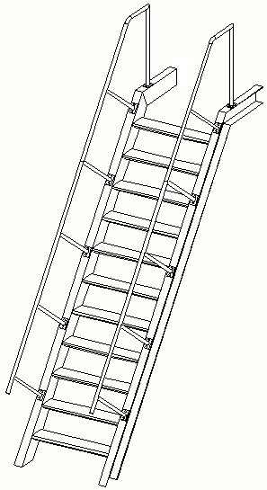
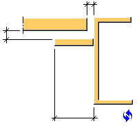
Type 1 Ship ladder with stringers, steps, stanchions, and handrails. |
|
|
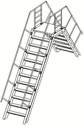
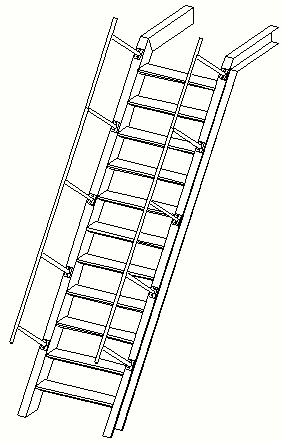
Type 2 Ship ladder with stringers, steps, stanchions, platform, and handrails with middle rails. |
|
|
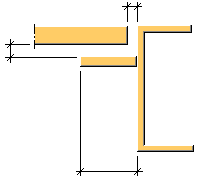
Type 3 Ship ladder with stringers, steps, stanchions, platform, handrails with middle rails. |
|
|
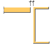
Type 4 Ship ladder with stringers, steps, stanchions, and handrails. |

Limitations
Ship Ladder uses catalog step profiles to define the step type on the Parts tab.
To have an updated step profile list on the Parts tab, you need to run the Steps.exe program when you use the Ship Ladder modeling tool for the first time in your environment, or when you change your Tekla Structures environment.
Warning:
With standard settings Tekla Structures overwrites the step profile settings and replaces them with the default values every time when Tekla Structures is started. To prevent Tekla Structures loosing the step profile settings, set XS_DO_NOT_OVERWRITE_PLUGIN_INP_FILE = TRUE in teklastructures.ini file.
If you are using catalog step profiles and have set XS_DO_NOT_OVERWRITE_PLUGIN_INP_FILE = TRUE and you update Tekla Structures, do the following:
-
Set XS_DO_NOT_OVERWRITE_PLUGIN_INP_FILE = FALSE in teklastructures.ini file.
-
Update Tekla Structures.
-
Start Tekla Structures.
-
Set XS_DO_NOT_OVERWRITE_PLUGIN_INP_FILE = TRUE in teklastructures.ini file.
-
Run Steps.exe.
-
Restart Tekla Structures
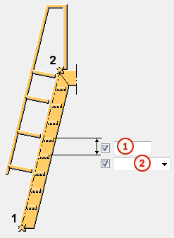
Selection order
-
Pick a point to indicate the bottom level of the stairs.
-
Pick a point to indicate the top level of the stairs.
-
Click the middle mouse button to create the component.
Points that indicate the bottom level and top level are usually nosing line start/end points.
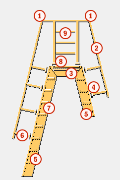
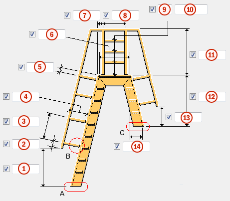
Part identification key
|
Part |
|
|---|---|
|
1 |
Elbow |
|
2 |
Handrail |
|
3 |
Platform support |
|
4 |
Plate |
|
5 |
Stringer |
|
6 |
Stanchion |
|
7 |
Step |
|
8 |
Platform |
|
9 |
Middle rail |
Picture tab
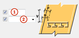
Use the Picture tab to control the type of the stairs, the dimensions of the parts created, horizontal offset, and horizontal distance between stringers.
Dimensions
|
Description |
Default |
|
|---|---|---|
|
1 |
Vertical distance between up stringer bottom and handrail bottom. |
1000 mm |
|
2 |
First stanchion offset along handrail, measured from the handrail bottom. |
200 mm |
|
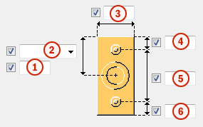
3 |
Maximum distance between middle stanchions. |
1000 mm |
|
4 |
Distance between stringer and handrail. |
800 mm |
|
5 |
Last stanchion offset along handrail, measured from the stringer top. |
200 mm |
|
6 |
|
1000 mm |
|
7 |
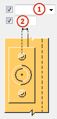
Horizontal offset for the first stanchion, measured from horizontal stringer start. This option is not active for Type 4. |
200 mm |
|
8 |
Distance between the first and the last horizontal stanchions. This option is not active for Type 1 or Type 4. |
600 mm |
|
9 |
Number of middle rails. This option is not active for Type 1 or Type 4. |
3 |
|
10 |
Middle rail spacing. Use a space to separate middle rail spacing values. Enter a value for each space between middle rails. For example, if there are 3 middle rails, enter 2 values. This option is not active for Type 1 or Type 4. |
Value of option 3 divided by number of spaces. |
|
11 |
Vertical distance between handrail top and platform top. This option is not active if for Type 4. |
1000 mm |
|
12 |
Vertical distance between platform top and down stringer bottom. This option is active only for Type 3. |
2000 mm |
|
13 |
Vertical distance between handrail bottom and down stringer bottom. This option is active only for Type 3. |
1000 mm |
|
14 |
Horizontal distance between up nosing line end and down nosing line end. This option is active only for Type 3. |
The up stringer and down stringers have the same inclination. |
Step and assembly creation
|
Option |
Description |
|---|---|
|
Create top step |
Define whether the top step is created. |
|
Create assembly |
Define which parts form an assembly. The options are:
|
Detail A and Detail C
Use Detail A to connect the up stringer end to an end detail.
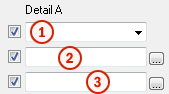
Use Detail C to connect the down stringer end to an end detail.

|
Description |
Default |
|
|---|---|---|
|
1 |
Define whether the stringers are connected to an end detail. |
None |
|
2 |
Define the detail by selecting it from the component catalog. |
|
|
3 |
Select an attribute file for the detail. |
standard |
Ship ladder options
|
Description |
Default |
|
|---|---|---|
|
1 |
Handrail elbow radius. This option is not active for Type 4. |
100 mm |
|
2 |
Define how to measure the dimension for the horizontal offset of the ship ladder. The options are:
|
Middle |
|
3 |
Horizontal offset. This option is not active for Default or Middle. |
0 mm |
|
4 |
Horizontal distance between stringers. |
1000 mm |
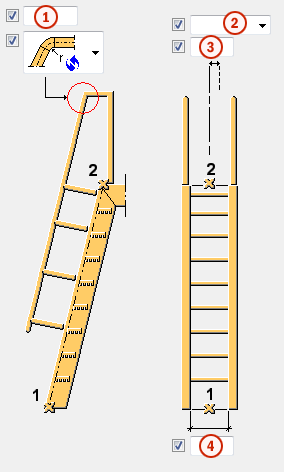
Handrail elbow bending cuts
This option is not active for Type 4.
|
Option |
Description |
|---|---|
|
|
Default Bent elbow AutoDefaults can change this option. |
|
|
Bent elbow Separate elbow part is between rails. |
|
|
Fitting Rails are fitted. |
|
|
Bent rail Rail is bent. |
|
|
Separate rails Rails are not fitted. |


Parts tab
Use the Parts tab to control the properties of the created parts.
Part properties
|
Option |
Description |
Default |
|---|---|---|
|
Elbow Handrail Middle rail Stanchion |
Define the elbow profile by selecting it from the profile catalog. |
PD40*2 |
|
Plate in Detail B |
Thickness of the plate. |
5 mm |
|
Support |
Thickness of the platform support. |
5 mm |
|
Step |
Select whether to use catalogue steps or profiles or to create the steps. Select the step from the list of catalogue steps or from the profile catalog. If you change your Tekla Structures environment, update the step list. |
|
|
Stringer |
Define the stringer profile by selecting it from the profile catalog. |
C200*100*5 |
|
Platform |
Thickness of the platform. |
50 mm |
|
Bracket |
Define the bracket profile by selecting it from the profile catalog. |
|
Option |
Description |
Default |
|---|---|---|
|
Pos_No |
Prefix and start number for the part position number. Some components have a second row of fields where you can enter the assembly position number. |
The default part start number is defined in the Components settings in . |
|
Material |
Material grade. |
The default material is defined in the Part material box in the Components settings in . |
|
Name |
Name that is shown in drawings and reports. |
|
|
Class |
Part class number. |
Platform tab
Use the Platform tab to control the platform offset and support.
Platform offset

|
Description |
Default |
|
|---|---|---|
|
1 |
Platform horizontal offset from the top step. If the top step is not created, the platform horizontal offset is defined from the up nosing line top point. |
0 mm |
Platform offset and support
|
Description |
Default |
|
|---|---|---|
|
1 |
Platform support vertical offset from the platform bottom. |
0 mm |
|
2 |
Platform horizontal offset from the stringer. |
0 mm |
|
3 |
Width of the platform support. |
50 mm |
Platform support creation
Note:
The top of the platform is always on the same level as the top of the stringer.
|
Option |
Description |
|---|---|
|
|
Default Platform support is created. AutoDefaults can change this option. |
|
|
Platform support is created. |
|
|
Platform support is not created. |
Steps tab
Use the Steps tab to control the step spacing and offset.
Step spacing
|
Description |
Default |
|
|---|---|---|
|
1 |
Vertical spacing between the steps. The spacing depends on the step spacing type. |
300 mm |
|
1 |
Step spacing type. The steps are spaced from the second picked point to the first picked point Equal represents the maximum distance between the steps. Exact represents the exact distance between the steps. |
Equal |
Step offset
|
Description |
Default |
|
|---|---|---|
|
1 |
Step offset from the stringers. |
0 mm |
|
2 |
Type of the step offset. |
Horizontal (H) |
Rails tab
Use the Rails tab to control the handrail and middle rail properties.
Middle rail and Handrail
|
Option |
Description |
Default |
|---|---|---|
|
Middle rail to stanchion Handrail to stanchion |
Define how the middle rails or handrails are connected to the stanchions. |
Middle rails = Connection Handrails = Weld |
|
Connection number |
Define a connection that connects the rails to stanchion by selecting it from the component catalog. |
Round tube (23) |
|
Connection properties |
Select an attribute file for the connection. |
standard |
Handrail options
|
Option |
Description |
Default |
|---|---|---|
|
Handrail max. length |
Maximum length of the handrail. |
3000 mm |
|
Handrail cuts |
Define how the handrails are cut.
|
At max. stanchion |
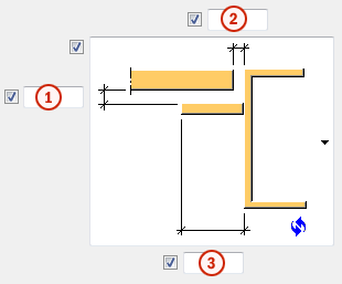
Detail B tab
Use the Detail B tab to control the bolt properties on a plate that connects stanchions to stringers.
Vertical offset
|
Description |
|
|---|---|
|
1 |
Plate vertical offset. |
|
2 |
Define how to measure the dimension for the plate vertical offset.
|
|
3 |
Plate width. |
|
4 |
Distance between top bolt and plate top. |
|
5 |
Distance between the bolts. |
|
6 |
Distance between bottom bolt and plate bottom. |
Horizontal offset
|
Description |
|
|---|---|
|
1 |
Define how to measure the dimension for the horizontal plate offset.
|
|
2 |
Horizontal plate offset. |
Bolting direction
|
Option |
Description |
|---|---|
|
|
Default From plate to stringer AutoDefaults can change this option. |
|
|
From stringer to plate |
|
|
From plate to stringer |


Bolt basic properties
|
Option |
Description |
Default |
|---|---|---|
|
Bolt size |
Bolt diameter. |
Available sizes are defined in the bolt assembly catalog. |
|
Bolt standard |
Bolt standard to be used inside the component. |
Available standards are defined in the bolt assembly catalog. |
|
Tolerance |
Gap between the bolt and the hole. |
|
|
Thread in mat |
Defines whether the thread may be within the bolted parts when bolts are used with a shaft. This has no effect when full-threaded bolts are used. |
Yes |
|
Site/Workshop |
Location where the bolts should be attached. |
Site |
Slotted holes
You can define slotted, oversized, or tapped holes.

|
Option |
Description |
Default |
|---|---|---|
|
1 |
Vertical dimension of slotted hole. |
0, which results in a round hole. |
|
2 |
Horizontal dimension of slotted hole, or allowance for oversized holes. |
0, which results in a round hole. |
|
Hole type |
Slotted creates slotted holes. Oversized creates oversized or tapped holes. No hole does not create holes. |
|
|
Rotate Slots |
When the hole type is Slotted, this option rotates the slotted holes. |
|
|
Slots in |
Part(s) in which slotted holes are created. The options depend on the component in question. |
Bolt length increase
Define how much the bolt length is increased. Use this option when, for example, painting requires the bolt length to be increased.

Bolt assembly
The selected check boxes define which component objects (bolt, washers, and nuts) are used in the bolt assembly.
If you want to create a hole only, clear all the check boxes.

To modify the bolt assembly in an existing component, select the Effect in modify check box and click Modify.
Welds tab
Click the link below to find out more: