Bracing cross (19)
Bracing cross (19) bolts one or more twin-profile braces to an existing gusset plate.
Tip: To create a gusset
plate, use the Standard gusset (1065) component, or create a countour
plate.
Objects created
-
Bolts
-
Cuts
-
Welds
Use for
| Situation | Description |
|---|---|
|
|
Brace profile: L Braces are bolted directly to the gusset plate. |
|
|
Brace profile: W Braces are notched around the gusset plate and bolted to the gusset plate. |


Before you start
Create a gusset plate, and 1 to 10 braces.
Selection order
-
Select the main part (gusset plate).
-
Select the secondary part (first brace).
-
Select the second secondary part (second brace).
-
Select the subsequent secondary parts (subsequent braces).
-
Click the middle mouse button to create the component.
Note:
Tekla Structures uses values in the joints.def file to create this component.
Picture tab
Use the Picture tab define the flange cut dimension.

| Description | |
|---|---|
|
1 |
Define the length of the flange cut. |
Parameters tab
Use the Parameters tab to cut the brace flange.
| Option | Description |
|---|---|
|
Fit secondary |
Select whether the secondary part is fitted. Selecting Yes fits the secondary part according to the bolt distances. |
|
Cut other side flanges
|
Select whether to create a triangular cut on the opposite side of the flange.
|

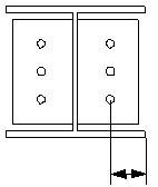
Bolts tab
Use the Bolts tab to define the bolt group dimensions and bolt properties.
Bolt group dimensions

| Description | |
|---|---|
|
1 |
Dimension for horizontal bolt group position. |
|
2 |
Select how to measure the dimensions for horizontal bolt group position.
|
|
3 |
Bolt edge distance. |
|
4 |
Number of bolts. |
|
5 |
Bolt spacing. Use a space to separate bolt spacing values. Enter a value for each space between bolts. For example, if there are 3 bolts, enter 2 values. |
|
6 |
Dimension for vertical bolt group position. |
|
7 |
Select how to measure the dimensions for vertical bolt group position.
|


Bolt basic properties
|
Option |
Description |
Default |
|---|---|---|
|
Bolt size |
Bolt diameter. |
Available sizes are defined in the bolt assembly catalog. |
|
Bolt standard |
Bolt standard to be used inside the component. |
Available standards are defined in the bolt assembly catalog. |
|
Tolerance |
Gap between the bolt and the hole. |
|
|
Thread in mat |
Defines whether the thread may be within the bolted parts when bolts are used with a shaft. This has no effect when full-threaded bolts are used. |
Yes |
|
Site/Workshop |
Location where the bolts should be attached. |
Site |
Slotted holes
You can define slotted, oversized, or tapped holes.

|
Option |
Description |
Default |
|---|---|---|
|
1 |
Vertical dimension of slotted hole. |
0, which results in a round hole. |
|
2 |
Horizontal dimension of slotted hole, or allowance for oversized holes. |
0, which results in a round hole. |
|
Hole type |
Slotted creates slotted holes. Oversized creates oversized or tapped holes. No hole does not create holes. |
|
|
Rotate Slots |
When the hole type is Slotted, this option rotates the slotted holes. |
|
|
Slots in |
Part(s) in which slotted holes are created. The options depend on the component in question. |
Bolt assembly
The selected check boxes define which component objects (bolt, washers, and nuts) are used in the bolt assembly.
If you want to create a hole only, clear all the check boxes.

To modify the bolt assembly in an existing component, select the Effect in modify check box and click Modify.
Bolt length increase
Define how much the bolt length is increased. Use this option when, for example, painting requires the bolt length to be increased.

Staggering of bolts
|
Option |
Description |
|---|---|
|
|
Default Not staggered AutoDefaults can change this option. |
|
|
Not staggered |
|
|
Staggered type 1 |
|
|
Staggered type 2 |
|
|
Staggered type 3 |
|
|
Staggered type 4 |
General tab
Click the link below to find out more:
Design tab
Click the link below to find out more:
Analysis tab
Click the link below to find out more:
Welds
Click the link below to find out more: