Unitechnik export: TS configuration tab
2019
Tekla Structures
Unitechnik export: TS configuration tab
Use the TS configuration tab to control the Unitechnik export properties.
Option |
Description |
|---|---|
Rotation |
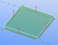
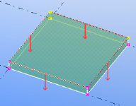
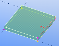
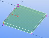
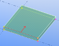
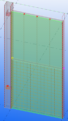
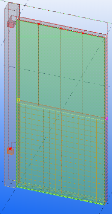
Select the scanning direction, which defines which main part face is towards the pallet base. Unitechnik export uses scanning layers to obtain the geometry of all parts in a cast unit. The scanning direction depends on the plane of the cast unit main part. A floor panel is scanned from bottom to top side. A wall panel and a column are scanned from one side to the other side. The position and direction of a basic shape of the exported cast unit depends on the rotation. Note that you can use the surface object user-defined attribute Use surface as pallet base to orient the object without changing the top-in-form face or the rotation in export settings. |
No Floor: Bottom to top Wall: Front to rear side (according to the modeling direction ) Column: Side to side
|
|
180 Floor: Top to bottom Wall: Rear to front side Column: From one side to the opposite side
|
|
+90 around X Floor: Left to right side Wall: Top to bottom Column: Side to side
|
|
-90 around X Floor: Right to left side Wall: Bottom to top Column: From one side to the opposite side
|
|
-90 around Y Floor: Rear to front side Wall: Right to left side Column: Top to bottom
|
|
With the Top in form face option, the scanning direction depends on the defined top-in-form-face , so that the opposite face will be towards the pallet. |
|
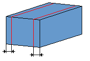
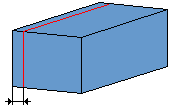
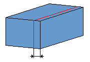
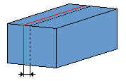
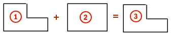
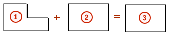
Examples of rotation:
|
|
Extra rotation |
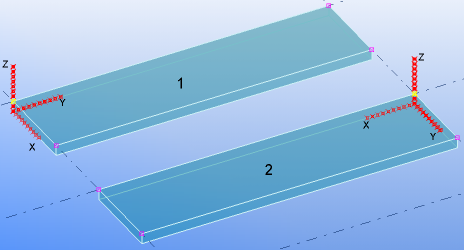
Select the rotation around the z axis, and thereby the rotation of the pallet. The z axis has the same direction, but the x and y directions are changed. To show the actual coordinate system, set Draw pallet axis to Yes on the Pallet tab.
The following example shows the coordinate system with no rotation and no extra rotation settings. Panel 1 has the z axis set parallel to the shorter side. It is incorrect in the Unitechnik format, so the coordinate system has to be rotated. Panel 2 shows a rotation by 90 degrees around the z axis.
|
Auto-rotate on pallet |
Select whether to auto-rotate the coordinate system for export +90° or -90° when the element width exceeds the pallet width, or when the element width exceeds the element length. |
Scan position |
The element contour, cutouts and line attributes are defined by scanning the cast unit in the scan direction defined by rotation settings above. A scanning plane works like a section with no view depth. The export application uses 1 or 2 scanning planes for each part included in the exported cast unit (regardless of the output file structure setting). The offset is towards the middle of panel from the scanning plane, but can be negative or positive value. The number of the scanning layers depends on the selected scan position. Each object of the cast unit is scanned in one direction. Select the position in which all parts are scanned. Each part is scanned separately. Scanning plane is parallel to the basic shape plane.
To move the position of the exact scanning plane, use the Scan position offset boxes below to define start offset and end offset. |
Merge CONTOUR layers |
You can export one scanned layer only. With two scanned layers, they have to be merged into one layer.
|
Export CUTOUTs |
To prevent cutout export, select No. Exclude selected excludes from the export the modeled cut parts that you define by class or name. Selected only includes in the export the cut parts that you define by class or name. |
Merge CUTOUT layers |
The same as Contour export , but for holes only. |
Merge CUTOUTs |
Select how to merge overlapping cutouts. You can select to export a big cutout which is created by smaller cuts as separate cutouts. The options are:
|
Extend contour and add formwork |
Select whether to extend the contour by embeds which are outside the element. |
Name for additional formwork (embed) |
Define a name for the embed. |
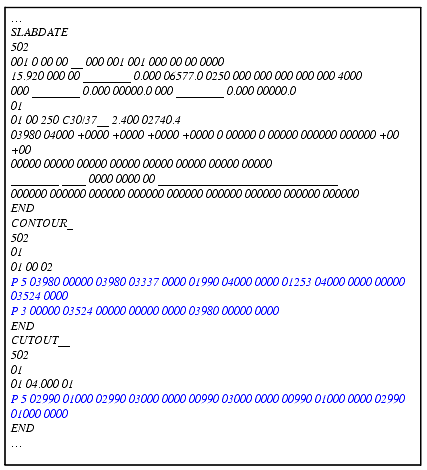
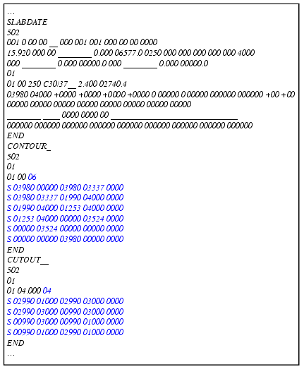
Geometry export |
Select whether the geometry of the exported part (concrete contour, cutout, mountpart) is represented as polygons or lines. Polygons exported:
|
Lines exported:
|
|
| Export rounded holes as circle (K) | Select whether you want to export rounded holes as circles (K) or polygons/lines. |
Double wall turned |
Select whether the first shell of a double wall on the pallet is turned. This requirement depends on the receiving master computer system. The options are: No : Exported as in model, shell1 is in front, shell2 in background. Yes, turn shell1 : The shell 1 is offset by the pallet width in y direction (defined on the Validation tab) and flipped around x axis Yes, turn shell1 - fixed edge up : This is meant for special machines. |


See also