Design comparison - with and without staged construction
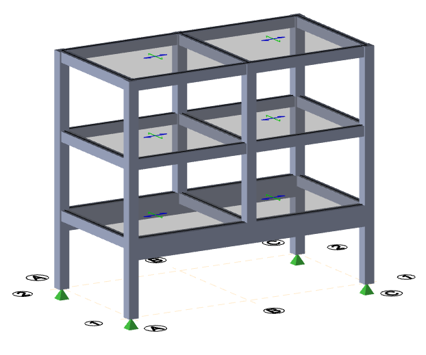
The following transfer beam model is used to demonstrate how Tekla Structural Designer effectively considers an envelope of design cases to ensure a realistic and safe design, (irrespective of whether staged construction is considered or not).
The envelope formed when staged construction analysis has not been considered is compared with the similar envelope formed when staged construction is taken into account, to see what effect it has on the design.
Design force envelope without staged construction
When the model is designed without taking account of staged construction, a design force envelope is established that considers the results of a 3D building analysis, and where appropriate grillage and FE chasedown analyses.
The design moments that result from the three analysis types are as follows:
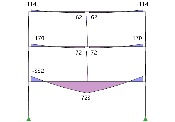
3D building analysis results
First-order linear analysis moments:
Frame effects in the building analysis model result in some of the load being shared between the transfer beam and the beams in the upper two levels.
The key question for engineers to consider here is - would you be happy if the second and third floor beams do not get designed for a hogging moment at the central (supporting?) column?
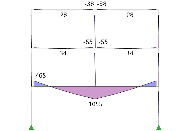
Grillage chasedown and FE chasedown results
Grillage chasedown moments:
FE chasedown moments:
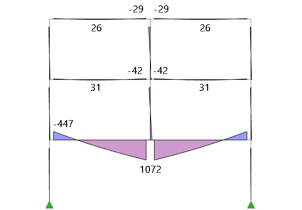
In both of the chasedown analysis models, (which aim to emulate how an engineer might design the structure by hand):
- more load is carried by the transfer beam,
- the second and third floor beams get designed for a hogging moment at the central column.
See the eLearning topic Background to the Analysis/Design procedures to gain a wider understanding of the benefits provided by the chasedown analysis models.
Design force envelope
| Member | Critical sagging moment (kNm) | Critical hogging moment (kNm) |
|---|---|---|
| 3rd floor beam | 62 (building analysis) | -114 (building analysis) |
| 2nd floor beam | 72 (building analysis) | -170 (building analysis) |
| 1st floor (transfer) beam | 1072 (FE chasedown) | -465 (Grillage chasedown) |
Because the members are designed for an envelope of design forces from each of the analyses this is a safe approach.
The concern of some engineers is that this envelope might be over-conservative and design efficiency can be achieved by another approach.
Design force envelope with staged construction
Staged construction can be considered by selecting Include staged construction analysis on the Analysis page of the Design Settings dialog box.
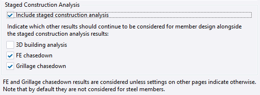
The other sets of design forces to be considered in the envelope are at the user’s discretion. The default as shown above is for the 3D building analysis not to be considered, while both the FE and Grillage chasedowns are considered.
The staged construction analysis results that are obtained will be dependent on a number of factors including the pace of construction and the amount of load applied in the construction stages.
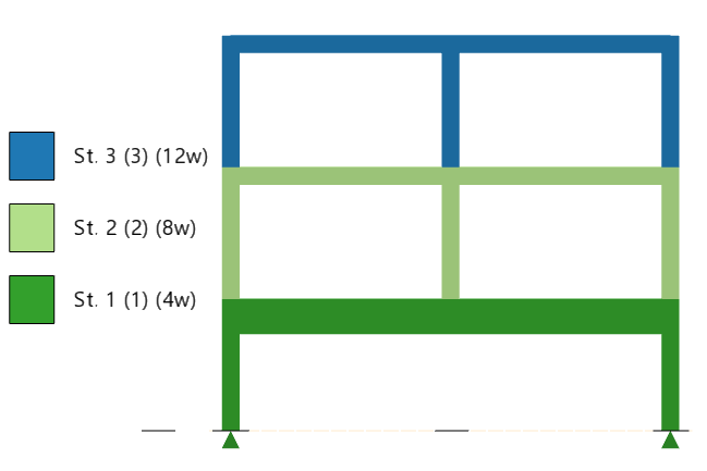
Pace of construction
In this example the duration and content of each construction stage has been specified as shown - each floor is placed in a separate stage, and each stage has a duration of four weeks.
If a faster pace of construction were to be adopted this would result in more creep occurring after the construction stages are complete. Faster construction therefore moves the results closer to those obtained by 3D building analysis.
Construction stage loading
By making a realistic estimate of the construction load you will obviously obtain more accurate results.
If minimal load were to be applied during construction, the balance applied in the design stages would be greater. Minimizing the construction stage loading moves the results closer to those obtained by 3D building analysis.
Staged construction analysis results
Staged construction analysis moments:
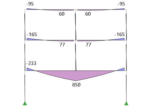
Staged construction analysis recognizes the changing state of a structure over time, (something that a simple 3D analysis completely ignores) and provided that the input parameters have been specified reasonably accurately can be considered more realistic.
Note that the second and third floor beams do not get designed for a hogging moment at the central column, chasedowns are the only way to mimic this traditional design expectation.
Grillage chasedown and FE chasedown results
The grillage and FE chasedown analysis results are unchanged, (as chasedown analysis models are separate from and not affected by staged construction analysis).
Grillage chasedown moments:
FE chasedown moments:
Design force envelope
The members are now designed for an envelope of design forces in which the 3D building analysis results have been replaced by the 3D staged analysis results.
| Member | Critical sagging moment (kNm) | Critical hogging moment (kNm) |
|---|---|---|
| 3rd floor beam | 60 (staged construction analysis) | -95 (staged construction analysis) |
| 2nd floor beam | 77 (staged construction analysis) | -165 (staged construction analysis) |
| 1st floor (transfer) beam | 1072 (FE chasedown) | -465 (Grillage chasedown) |
The chasedown results still govern when determining the maximum hogging and sagging moments in the transfer beam at the first floor, so its design is unchanged.
The 3D building analysis results previously governed the design of the second floor beam, but in the envelope formed for staged construction it is now the smaller 3D staged analysis results that govern.
Conclusions
The chasedown results will always govern the design of the transfer beam, so provided they are not deactivated it will always be designed safely.
For other beams in this model the 3D building analysis results initially govern. By replacing them with the staged construction analysis results it is possible to tighten up on the design. By using better estimates for the staged construction input parameters more accurate results can be achieved.