
Stiffening effect of semi-rigid diaphragms on core walls with openings
The connection between slab semi-rigid diaphragms and meshed concrete walls has been improved starting with Tekla Structural Designer 2026 SP2. This improvement results in a greater stiffening effect on concrete core walls with openings compared to previous versions of Tekla Structural Designer.
The impact of the change is examined in more detail below.

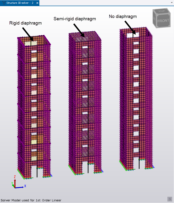
The model shown above illustrates three variations of a laterally loaded concrete core tower structure. Each tower has a concrete slab at each level. The levels are configured so that none of the slabs are meshed in the 3D analysis. The only difference between the towers is how the diaphragm option has been configured for their respective slabs:
-
The slabs in the left hand tower are configured to act as a Rigid Diaphragm (RD) at each level.
-
The slabs in the central tower are configured to act as a Semi-Rigid Diaphragm (SRD) at each level.
-
The slabs in the right hand tower have no diaphragms specified.
When analyzed, the corresponding solver models are as follows.
The analysis results obtained before the release of Tekla Structural Designer 2026 SP2 were as shown below:

The analysis results from Tekla Structural Designer SP2 onward are:

The overall deflection at the top-right corner of each tower is indicated by the red text.
Observe the following points:
- Before Tekla Structural Designer 2026 SP2, the SRD was disconnected from the wall at intermediate points, which meant that deflection in the panel would be similar to that obtained when no diaphragm is present. Therefore, the results from Tekla Structural Designer 2026 SP2 show a clear improvement.
-
The deflection in Tower 2, (the tower with the SRD), has dropped from 40.4 to 36.8mm. The reason for this is discussed below.
In each tower the meshed wall above each opening functions as a coupling beam. The deflection is smaller in Tower 2 because the semi-rigid diaphragm (SRD) effectively adds a "flange" to this beam (as indicated by the purple shading below).

Although this may be challenging to visualize, at one end of the coupling beam, the "flange" experiences tension, while at the other end, it experiences compression.

This behavior observed in Tower 2 is consistent with the results that would occur if the slabs in the other towers were meshed within the 3D analysis model, as illustrated below.

When the slabs are meshed, the deflections in Towers 1 and 3 reduce, becoming similar to those observed for the unmeshed Tower 2. However, it should be noted that the unmeshed Tower 2 results were obtained with a default stiffness adjustment factor of 1.0 applied. When stiffness reduction factors are applied to the slabs in Tower 2, the deflections vary as shown in the following table:
| “Divide Stiffness by” factor | Top Corner Deflection |
|---|---|
| 1 | 36.8 |
| 5 | 38.2 |
| 10 | 38.9 |
| 100 | 40.0 |
| 1000 | 40.3 |
From the information above, it can be concluded that, if you need to mitigate the stiffening effect when the concrete slabs are acting as Semi-Rigid Diaphragms (SRDs), you should consider adjusting the default stiffness division factor.