Timber design using Tekla Tedds enhancements
Multiple enhancements
A number of enhancements have recently been made to Timber Design using Tekla Tedds giving a more accurate and more user friendly design experience for design to both the Eurocode (all supported NA’s) and USA codes. The enhancements enable engineers to optimize their timber structure designs using more detailed designs with similar or better performance than in previous releases. These enhancements were first introduced with release 2022 SP1.
The enhancements are:
-
More detailed and hence potentially more optimized design via:
-
Automatically generated multiple design cases; each design case groups load combinations by load type (Live/ Imposed, Wind, Snow…etc)
-
Automatic application of design factors related to load duration to the appropriate design case.
-
-
Significant speed improvements made within both Structural Designer and Tedds allow the more detailed design to be completed in similar or faster times to previously.
-
Automatic generation of Timber Design combination envelopes that correspond with the design cases used for timber design.
-
Easy identification and navigation between design cases in the Tedds calculation interface.
Design of a timber member from TSD with 8-10 design cases takes about the same time as the single design envelope case did previously. See below for more details on each enhancement:
-
Multiple design cases & load duration factors - The approach to processing analysis results into design cases is much improved. Load combinations are now grouped by load type (Live/ Imposed, Wind, Snow…etc), allowing a more accurate assignment of design factors associated with load duration to the appropriate analysis results. This creates more accurate timber designs. The previous approach conservatively used a single design envelope of all analysis results and a single critical load duration design factor. (termed “Load duration factor” for NDS ASD and Eurocode and “Time effect factor” for NDS LRFD).
-
As shown in the picture below, the new design cases are listed for selection at the top left of the Tedds Timber/ Wood design calculation interface. The appropriate load duration factor is set automatically for each design case as illustrated.
-
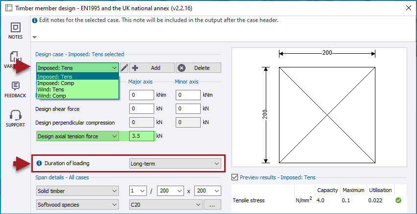

-
Note that the Load duration/ Time effect factor is automatically set for each combination in Tekla Structural Designer and can be reviewed and edited in the Loading > Combinations dialog as shown below.
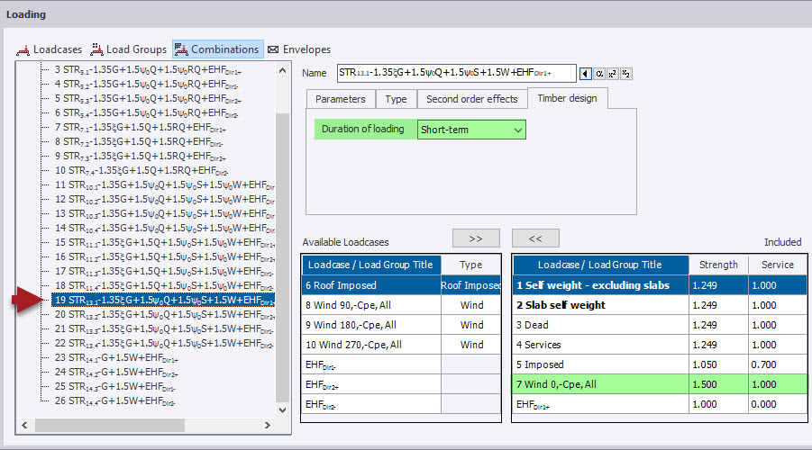
-
Timber Design Envelopes - load combination envelopes that correspond to the design cases used for timber design in Tedds can now be automatically generated. To do this, in the Loading > Combinations dialog select the new option Generate > Timber Design Envelopes, as shown in the picture below.
- Note that the generation of these envelopes is NOT a required part of the design process and you do not have to generate them. The option has been added to aid transparency of the design process for timber and in case the engineer should wish to review these results.

-
Improved Tedds Calculation Interface - Named design cases and additional labeling in the Tedds interface make navigation of design cases and design options easier.

-
[TSD-11234] - Bearing check removed
Note that, as part of these enhancements, the bearing check portion of the Tedds timber member design calculation is now disabled, since it only accommodates a single check and is more of a connection consideration. Hence the Design reaction/ perpendicular compression values in the calculation interface are set to zero and are grayed out.
New deflection checks
This enhancement adds comprehensive assessment and checking of member deflections for both Eurocode and US Regional Codes. The new feature includes the option to calculate and include the effects of creep deformation for long term deflection checks.
For more about the overall timber design workflow and how this exciting new feature sits within it, see these new videos: Learn how to design timber members in Tekla Structural Designer using Tekla Tedds (Eurocode) and Learn how to design wood members in Tekla Structural Designer using Tekla Tedds (USA). This enhancement was first introduced with release 2022 SP2.
With this new feature, deflection checks can now be included in the overall design checks for timber beams, with the specifics of each Regional Code as follows:
-
US Code checks include:
-
Dead, Live, Snow, Wind, and Total loads for instantaneous deflections
-
Total load deflections can optionally consider the effects of creep deformation in design
-
-
Eurocode checks include:
-
Dead, Imposed, Snow, Wind, and Total loads for instantaneous deflections
-
Total load deflections can optionally consider the effects of creep deformation in design
-
Key aspects of the new feature are:
New Timber Member Deflection Properties
Comprehensive new deflection limit settings are added for timber members in the same manner as the existing ones for steel members.
-
Just as for steel members, the Deflection limits settings are available via both the Properties Window for selected member(s) and via the individual member properties dialog. They include both relative span/ factor and optional absolute values for each criteria.


New Deflection Functionality in the Tedds Timber Design Calculation
To cater for the new deflection checks, the Tedds Timber Design Calculation is enhanced as follows:
-
Deflection Design Cases - additional deflection design cases are automatically added to the strength design cases for every Tedds design that is created. The load combination that governs the deflection is identified in each deflection design case name.

-
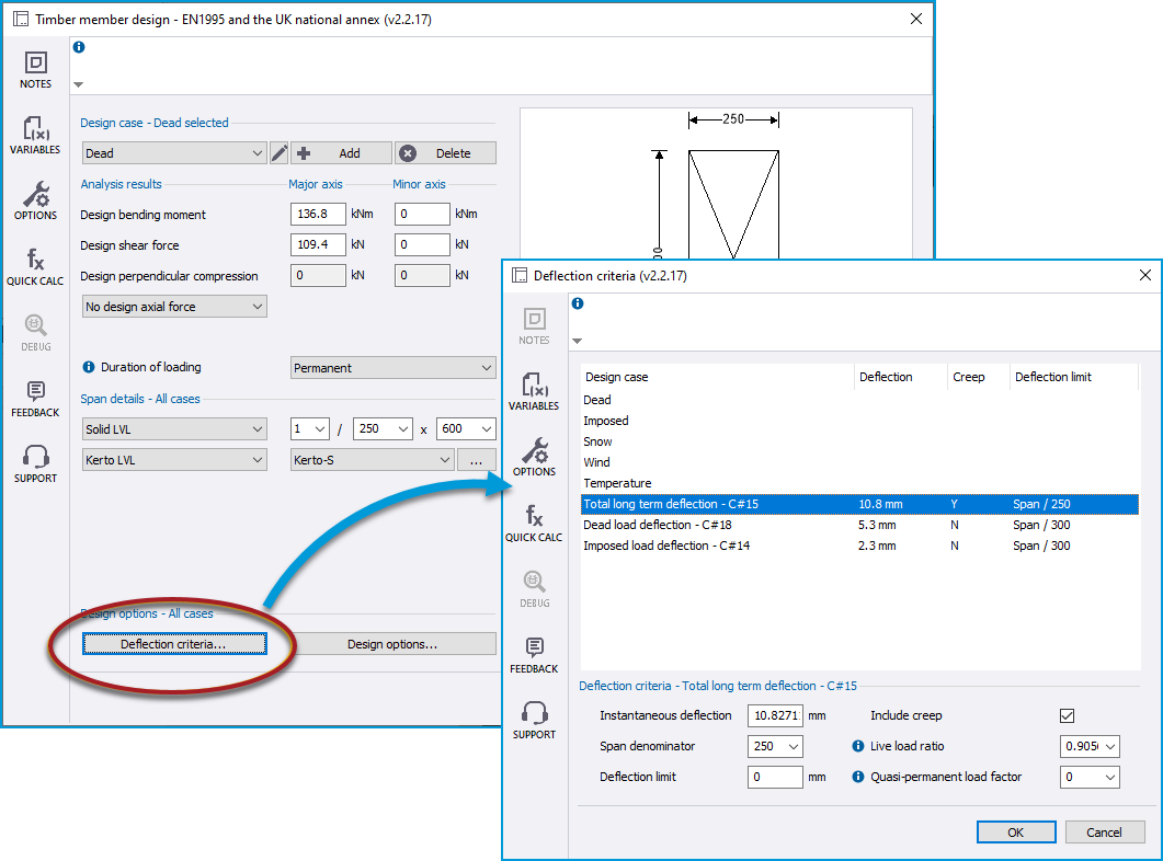
All deflection design cases and properties can be individually viewed and managed from the Deflection criteria dialog within the Tedds interface.
Long term deflections due to creep effects
Optionally you can also include the effects of creep deformation for long term deflection checks.
-
New Design Setting - this is controlled by the new setting “Include long term effects in total load deflection check” in Design Settings > Timber as shown in the pictures below.
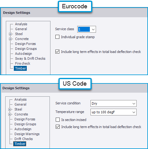
-
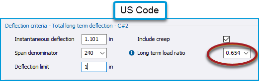
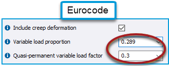
Long term load ratios/ factors are automatically calculated appropriate to the Regional Code and populated to the Tedds calculation deflection criteria, as shown below.
-
The final deflections are determined in the Tedds calculation and displayed in the preview results as shown below:

-
Automatic adjustment of design deflection value - you can adjust the modulus of elasticity and moment of inertia values in Tekla Structural Designer as you wish, to create the desired distribution of forces in a model. The deflection values used in design are adjusted to determine the relative member deflection value assuming an unfactored moment of inertia and using the Emean value typically recommended for serviceability checks under normal conditions.
New streamlined single column lift design
A multi-stack column ‘Lift’ (consisting of several stacks between floors all having the same section size) can now be designed using a single instance of the Tedds timber design calculation for the entire lift. Previously it was necessary to run the calculation separately for each stack, and any change to the section size needed to be manually re-applied at each stack. The new streamlined lift design process can be significantly quicker than the previous one. This enhancement was first introduced with release 2022 SP2
-
Note that, while the use of an envelope for the entire lift (as described below) may produce a more conservative design in some situations, any such conservatism can be removed if necessary by specifying splices between stacks (while retaining the same section size above/ below the splice) as required.
Some key aspects of the new design are:
-
Design forces and unbraced lengths - each design case is established using an envelope of the maximum forces in each direction from all stacks in the lift. The major and minor axis unbraced lengths are taken from the longest stack in the lift.


-
Design for Ungrouped/ Grouped columns - for an ungrouped column, design is performed using the enveloped lift forces, after which all stacks in the lift are automatically checked using their individual stack lengths and member forces. For a grouped column, a similar process is followed, other than the design being performed using the enveloped group lift forces, after which all stacks in the group are automatically checked using their individual stack lengths and member forces.


-
Design Process - the design process will depend on whether column grouping is enabled (Design Settings > Design Groups > Timber Beams/ Columns/ Braces) and also on what has been selected for the design.
-
Ungrouped design:
-
Design using Tekla Tedds > Member - with an individual stack selected
-
The lift containing the selected stack is designed for its LIFT forces.
-
All stacks in the lift are then checked for their individual stack MEMBER forces.
-
-
Design using Tekla Tedds > Member - with an entire column selected
-
All lifts in the column are designed for their LIFT forces.
-
All stacks in all lifts are then checked for their individual stack MEMBER forces.
-
-
Design performed from Review Data > Design Summary - by clicking the Results.. button adjacent to a stack
-
The lift containing the selected stack is designed for its LIFT forces.
-
All stacks in the lift are then checked for their individual stack MEMBER forces
-
-
-
Grouped design:
-
Design using Tekla Tedds > Group
-
All lifts are designed for the respective lift GROUP forces.
-
All stacks of all lifts in the group are then checked for their individual stack MEMBER forces.
-
-
Design using Tekla Tedds > Member - with an individual stack selected
-
The lift containing the selected stack is designed for its LIFT forces.
-
All stacks of this lift in the group are then checked for their individual stack MEMBER forces.
-
The designed lift is also checked for the lift GROUP forces so as to be available for export of group to Tedds.
-
-
Design using Tekla Tedds > Member - with an entire column selected
-
All lifts in the column are designed for their LIFT forces.
-
All stacks in all lifts in the group are then checked for their individual stack MEMBER forces.
-
The designed lift is also checked for the lift GROUP forces so as to be available for export of group to Tedds.
-
-
Design performed from Review Data > Design Summary - by clicking the Results.. button adjacent to a stack
-
The lift containing the selected stack is designed for its LIFT forces.
-
All stacks of this lift in the group are then checked for their individual stack MEMBER forces.
-
The designed lift is also checked for the lift GROUP forces so as to be available for export of group to Tedds.
-
-
-
-
Export to Tekla Tedds - a detailed report can be obtained by exporting to Tedds. The result will depend on what has been selected for the export.
-
Export to Tekla Tedds > Member - with an individual stack selected
-
The selected stack is exported with the design performed for the stack MEMBER forces
-
-
Export to Tekla Tedds > Member - with an entire column selected
-
All stacks in all lifts in the column are exported with the design performed for the stack MEMBER forces
-
-
Export to Tekla Tedds > Group
-
All lifts in the column are exported with the design performed for their LIFT forces
-
-