2021 SP1: Steel column base plate design - enhanced scope for USA head code
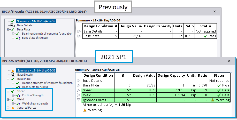
The scope of Steel Column Base Plate Design checks is significantly enhanced in this release for the USA Head Code, making it applicable to a wider range of loading conditions. Major axis shear loading is now checked for the shear resistance of the rods and/ or concrete and the welds are now also checked as shown in the picture below. In addition, all the applied forces are reviewed and beyond scope and/ or Ignored forces warnings issued as appropriate for cases that are not considered by the design. For full details of the checks performed, please see the updated Help Topic Column base plate design to AISC 360.
-
The enhanced and new checks are as follows for applied Major axis shear load - both with/ without Positive vertical load.
-
Base Plate
-
Bearing strength of concrete foundation.
-
Base plate thickness.
-
-
Shear
-
Friction Strength
-
Shear strength of rods
-
Concrete anchorage strength for shear forces on rods
-
Concrete pry-out strength of anchor rod in shear
-
-
Weld
-
Weld shear strength
-
-
-
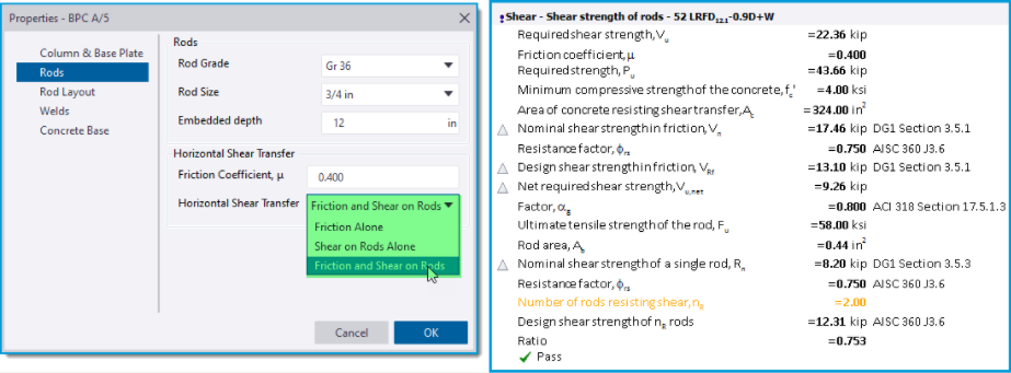
Shear Check - the shear capacity calculations performed are dependent on the Horizontal Shear Transfer option selected in the settings page/ group for “Rods” as shown in the picture below left. This has options of; Friction Alone (default), Shear on Rods Alone and Friction and Shear on Rods. The picture below right shows an example of the check details for the shear strength of rods with the Friction and Shear on Rods option selected. Below we give some brief details of checks performed and their references - for fuller details please see the updated Help Topic Column base plate design to AISC 360.
-
Friction Alone - for this the shear strength check is calculated in accordance with ACI 318 and considers the full (major) shear force. Note the following:
-
Since ACI 318 only considers LRFD requirements, this check is not performed for ASD load combinations.
-
The default for μ, the coefficient of friction between the base plate and concrete, is taken as 0.4 per ACI 349-01 (section RB.6.1.4), 349-06 and -13 (section RD.6.1.4).
-
-
Shear on Rods Alone - checks for this option are divided into the following three separate parts and consider the full (major) shear force: 1) Shear strength of rods 2) Concrete anchorage strength for shear forces on rods 3) Concrete pry-out strength of anchor rod in shear. Note the following:
-
The anchor rod strength is calculated in accordance with AISC 360 and AISC Design Guide 1 for both LRFD and ASD load combinations.
-
For the concrete strength checks - these are calculated in accordance with ACI 318 and since this only considers LRFD requirements these checks are not performed for ASD load combinations.
-
-
Friction and Shear on Rods - when this option is selected, the three Shear on Rods checks consider a net shear force i.e. the remaining (major axis) shear force not taken by frictional resistance alone.
-
Checks for Friction and Shear on Rods are divided into the same three separate parts as for Shear on Rods Alone described above, with the addition of a Friction calculation at the start of each of the three Shear on Rods parts that derives the net (major) shear force
-
-
-
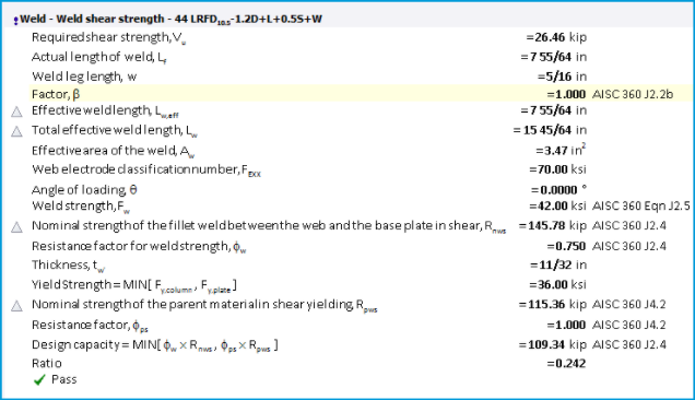
Weld Check - the welds are checked for one design condition: shear.
-
Weld Shear Strength
-
For base plates with thickness <= 3/4 in (19 mm), the default weld leg length is 1/4 in (6mm) and for all other base plate thicknesses the default weld leg length is 5/16 in (8 mm). These defaults can be adjusted in the database [Home > Materials > Welds > Defaults].
-
AISC 360-10 and -16 stipulates that, when the length of the weld exceeds 300 times the leg size, w, the effective length shall be taken as 180w (section J.2b.(d).(3)), and this is similarly applied when AISC 360-05 has been selected for steel design.
-
-
-
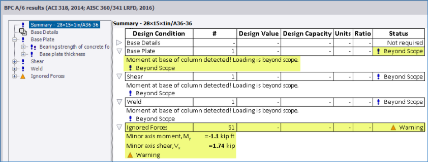
Beyond Scope/ Ignored forces - all the forces applied to a base plate connection are now fully reviewed and compared to those considered by the design. Where they are beyond scope and/ or ignored, an appropriate status is issued in the check details and reflected in the Review View > Design Status and connection entity tooltip. The picture below is an example of the check details showing this.
-
Beyond Scope - this status is issued for applied negative vertical load (uplift) or major axis moment. No design checks are performed for combinations where either or both of these are present.
-
Ignored forces - this applies to minor axis moment and shear; where their value is greater than a given limit*, they are displayed in the check details together with a Warning status. Where all other forces are within scope, all the design checks are carried out and the engineer can make a judgement on their validity.
-
*The given limits are defined on the Design Forces page of the Design Settings dialog available from the Design tab on the ribbon.
-
-