Steel single, double angle and tee section design to EC3
Unless otherwise stated all calculations are in accordance with the relevant sections of EN 1993-1: 2005 (Ref. 1).
Design method
The EC3 (Ref. 1) design
method adopted is dictated by the member characteristic type:
- “Beam”, “Truss member top” or “Truss member bottom” characteristic:
- Member is designed for axial tension, compression, shear, bending and combined forces - consistent with the method detailed in Steel Beam Design to EC3
- “Brace”, “Truss internal” or “Truss member side” characteristic:
- Member is designed for axial tension, compression and compression buckling only - consistent with the method detailed in Steel Brace Design to EC3
Note: Additional limitations
have to be considered when designing angle and tee sections to the above design
methods (as described below).
Limitations
In the current version when designing tees, single, and double angles to EC3, the
following checks remain beyond scope:
In addition, the following limitations apply:
| Tee | Angle | Double angle | |
|---|---|---|---|
| Classification | ok | ok | ok |
| Axial tension | ok | ok | ok |
| Axial compression | ok | ok | ok |
| Shear | ok | ok | ok |
| Buckling | ok | ok | ok |
| Combined strength | ok | ok | ok |
| LTB | Beyond scope | ok | Beyond scope |
| Combined buckling | Beyond scope | Beyond scope | Beyond scope |
| Deflection | ok | ok | ok |
- All sections and in particular single angles are assumed to be effectively loaded through the shear center such that no additional torsion moments are developed. In addition no direct allowance is made for 'destabilizing loads'.
- Design excludes bending of the outstand leg of single and double angles loaded eccentrically e.g. supporting masonry.
- Conditions of restraint can be defined as top and bottom flange for lateral torsional buckling LTB. It is upon these that the buckling checks will be based. For the current release intermediate LTB restraints are omitted (i.e. only fully restrained for LTB, or unrestrained).
- Single, double angles and tee sections subject to moment with high shear are beyond scope.
Section axes
For all sections:
- y-y is the axis parallel to the flanges (major axis)
- z-z is the axis perpendicular to the flanges (minor axis)
- for Single angles and Double angles
- z-z parallel to long side (leg) - single angles
- z-z parallel to long side (leg) - double angles with long leg back to back
- z-z parallel to short side (leg) - double angles with short leg back to back
- u-u is the major principal axis for single angles
- v-v is the minor principal axis for single angles
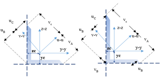 |
| Single angles - Section axes |
Classification checks
For axial compression and bending both the web and flange (Leg 1 and Leg 2) are classified as Class 1, Class 2, Class 3 or Class 4 and the worst of the two is the resultant classification for that cross section.
The rules from Table 5.2 (sheet 2 of 3) of EC3 are used for tee sections. In particular the rules of “Part subject to compression” are used to classify the tee section since these are more conservative compared to the limits of “Part subject to bending and compression”.
For double angles and single angles the rules from Table 5.2 (sheet 3 of 3) of EC3 are used.
Note: Class 4 section classification is
only allowed for tees, double angles and single angles.
Axial tension check
Section 6.2.3 of EC3 is used for this design check.
Axial compression check
An axial compression capacity check is performed according to clause 6.2.4.(1)
Shear check
Section 6.2.6 of EC3 is used for this design check.
Moment check
Section 6.2.5 of EC3 is used for this design check.
Note: Tees, double angles and single angles
are designed as Class 4. Equation 6.15 is used for class 4 slender
sections.
Note: Tees, double angles and single
angles subject to moment with high shear are beyond scope.
Moment capacity for Class 4 slender sections:
Class 4 sections are designed as Class 3 effective sections.
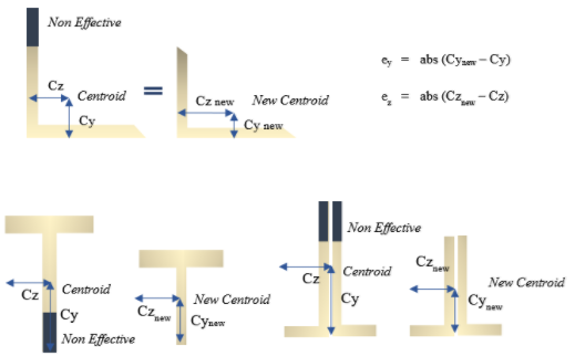
Hence, additional moments are induced in the member due to the shift of the centroid of the effective cross-section compared to that of the gross section when under axial compression only.
Thus:
ΔMEd,y = ey × NEd,max
ΔMEd,z = ez × NEd,max
Where:
NEd,max is the max compressive force in the span.
For tees and double angles ey = 0. Hence, total minor design moment = minor design moment.
Where:
ey and ez = the shift of the centroid of the effective area Aeff relative to the centre of gravity of the gross cross section
ey = abs(cynew – cy)
ez = abs(cznew – cz)
So finally, a total moment is obtained for which the moment design check is performed:
Mtotal y = Abs(MEd,y) + Abs(ΔMEd,y)
Mtotal z = Abs(MEd,z) + Abs(ΔMEd,z)
Single angles - asymmetric sections:
Single angles with continuous lateral – torsional restraint along the length are permitted to be designed on the basis of geometric axis (y, z) bending.
Single angles without continuous lateral – torsional restraint along the length are designed using the provision for principal axis (u, v) bending since we know that the principal axes do not coincide with the geometric ones.
ΔMu = ΔMy × cosϑ + ΔMz × sinϑ
ΔMv = -ΔMy × sinϑ + ΔMz × cosϑ
Note that when principal axis design is required for single angles and the classification is Class 4, all moments are resolved into the principal axes (total moment in the principal axes u-u and v-v).
Combined bending and axial check
Section 6.2.9 of EC3 is used for this design check.
For Class 3 - Equation 6.42 is applied:
Abs (NEd / A) + abs (My,Ed /Wel,min,y) + abs (Mz,Ed/Wel,min,z) ≤ fy / γM0
For Class 4 - Equation 6.43 is applied:
Abs (NEd/Aeff) + (abs (My,Ed) + abs (ΔMy,Ed)) / Weff,min,y + abs (Mz,Ed) + abs (ΔMz,Ed)) / Weff,min,z ≤ fy / γM0
Note that total moments are used when the section classification is Class 4.
For Class 4 cross section capacity - Equation 6.44 is applied.
Lateral torsional buckling check
Note: LTB check for tees and double angles is currently beyond scope.
EC3 is completely silent on LTB check for asymmetric sections such as single angles and mono-symmetric sections such as double angles and tees.
Hence we follow the approach of the Blue Book (Ref. 10):
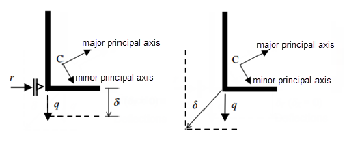
Firstly we calculate the equivalent slenderness coefficient (φ) (From Blue book) and the equivalent slenderness λLT (BS approach).
Then we find the non-dimensional slenderness  in order
to follow the EC design approach.
in order
to follow the EC design approach.
Conservatively we have taken: 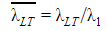
Note: All intermediate LTB restraints for single angles, double angles and tees are
ignored.
Compression buckling check
Section 6.3.1.1 of EC3 is used for this design check.
Effective length:
The value of effective length factor is entirely at the user’s choice. The default value is generally 1.0 although for truss members, there are special settings for the effective length depending upon the type of section and its position in the truss.
Different values can apply in the major and minor axis. Coincident strut restraint points in these two directions define the length for torsional and torsional flexural buckling and this can also have an effective length factor (this is assumed to be 1.0 and cannot be changed).
There is no guidance in EC3 on the values to be used for effective length factors for beam-columns although Annex BB does contain some information on the effective lengths to be used in trusses but not for single, double angles and tees.
It is the responsibility of the user to adjust the value from 1.0 (for the effective length factor) and to justify such a change on the compression page.
For tees:
Check:
- the buckling length in the major axis – Use Lyy = L * major factor
- the buckling length in the minor axis – Use Lzz = L * minor factor
- the buckling length for the torsional mode – Use Lxx = 1.00 * minor factor
For single and double angles:
Check:
- the buckling length in the major axis – Use Lyy = L * major factor
- the buckling length in the minor axis – Use Lzz = L * minor factor
- the buckling length for the torsional mode – Use Lxx =1.00 * L
- Double angles – Check as single angle
- Use Ly = Lyy/ 3
- Use Lz = Lzz/ 3
- Use Lx = Lxx/ 3
- Double angles – Check as double angle
- Double angles – Check as single angle
- the buckling length for the principal axis, v-v – Use Lvv = 1.00 * L
- Double angles – Check as single angle
- Use Lv = Lvv/3
- Double angles – Check as single angle
For double angles for (4) & (3a) minor principal axis buckling & torsional buckling respectively – half of the axial force and half of the double angle area is used.
Combined buckling check
In the current version this check is beyond scope for single angles, double angles and tees.
Deflection of single angles
If a single angle is continuously restrained the major geometric moment and major geometric section properties are used in the general equation governing the beam deflection.
 |
| Single angle deflections (continuously restrained, unrestrained) |
However, because single angle geometric axes are not coincident with the principal axes; a different procedure is required if the angle is not continuously restrained, the procedure being as follows:
- External loads are transposed from the geometric axes to the principal axes.
- The deflection equations are used to calculate deflections in the principal axes.
- These principal axis deflections are then transposed to geometric axes again.