Tekla Structural Designer 2018i release notes
2018i
Tekla Structural Designer
Link to download
Environment
Not environment-specific
This release will upgrade your Tekla Structural Designer installation to version number 18.1.0.45 and should be installed to ensure optimum function of the program. It includes a number of significant new features together with several enhancements and issue resolutions as detailed below.
If you are upgrading from a version earlier than Tekla Structural Designer 2018 SP4 (version 18.0.4.9) you can find details of enhancements and fixes included in all previous releases in Tekla User Assistance (TUA) and Tekla Downloads via the links below:
- Tekla User Assistance Main version release notes
- Tekla User Assistance Service Pack release notes
- Tekla Downloads
Licensing & Installation
- Licensing:
- New Licenses - no new license is required for this version.
- Installation:
- Integration
- Tekla Portal Frame Designer 18.1 and Tekla Connection Designer 18.1 - if you wish to integrate Tekla Structural Designer 2018i with Tekla Portal Frame Designer and/or Tekla Connection Designer you MUST install Tekla Portal Frame Designer 18.1 and/or Tekla Connection Designer 18.1 availble from Tekla Download Service
- 32-bit - As previously notified here there is no 32-bit version of this release. Hence only 64-bit operating systems are now supported on which the 64-bit version of the program will be automatically installed. Please see System Requirements for more information.
- Previous Versions and file compatibility - to aid with transition, this release will install alongside existing versions and does not overwrite them. Files from all previous versions can be opened in Tekla Structural Designer 2018i however note that, once saved, they cannot then be opened in an older version. If you wish to retain this option we therefore recommend using the File > Save As… option to save a new version of the file in Tekla Structural Designer 2018i and retain the original.
- Databases - in this release Material and Section databases are updated. A message that a new databases are available will be displayed in the Process Window as shown below when this release is installed and run for the first time.
Image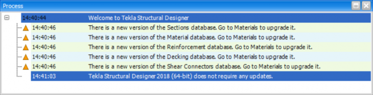
- Upgrade your local section databases as follows;
- Open “Materials” from the Home Ribbon, select the “Sections” page in the list of options, click the “Upgrade” button, then click this button again in the subsequent “Upgrade Database” dialog. Repeat this process for all the other databases (Material, Reinforcement...etc ) to ensure all your databases are up to date.
- United States AISC Sections - Section Order Lists - new order lists have been added incorporating new AISC sections (notably a number of new W sections). These will automatically be added when the Sections database is upgraded and can be reviewed via Home > Materials > Sections > Manage Section Orders. The original order lists “W Shapes” and “W” are retained with the new W sections added and will be included in these in a fresh installation. For an existing installation note the following:
- The Section Orders “W Shapes” and “W” in old or new models will not automatically contain the new W sections, but they will appear as available and can be added manually in the Edit Section Order dialog as shown below.
- To automatically update to the new configuration - i.e. with the new W sizes added and all sizes sorted by Mass - the Reset command can be used - select “W Shapes” or “W” and click the “Reset” button in the Edit Section Order dialog as shown below.
Note that this will overwrite any user-edits to the order list.
Image
- Integration
Issues with Associated Bulletins
- [TSD-685]1 - Concrete Column Design - Sections with Holes - the area of concrete removed by any section holes was ignored in the calculation of the Ultimate Axial Resistance. Note that for most design codes the ultimate axial load resistance is inherently checked in the section capacity checks so this was not in general a safety issue. However for design to ACI 318 there could be potential for un-conservative design since the ultimate axial resistance value is capped to reserve moment strength for the code prescribed minimum level of design load eccentricities. For more information please see Product Bulletin PBTSD-1809-2.
- This issue is addressed in this release.
Highlights
Graphical Results - Animation of Displacements
- The 1D and 2D displacements can now be animated in the Slab Deflection view and Results View. This applies to both static displacements and those for vibration and buckling analysis. Animation is begun by choosing the new “Animate…” option from the Scene Context menu. Animation begins immediately this is selected and a small dialog appears containing animation controls. These can be edited and applied at any stage during animation. The scene view can be fully controlled as normal - by zooming, rotating etc - while animation is ongoing. Simply close the Animation dialog to cease animation.
Image
Design - All Head Codes
Foundation Design - Pad Base (Spread Footing) Design Enhancements
The following significant enhancements are made to the design of Pad Base footings:
- Biaxial Uplift - the base pressure calculation now caters for loading which produces partial contact about both axes (biaxial uplift) . The process identifies the corners in bearing then calculates the ultimate bearing pressure at each corner, from which design pressures and internal design moments and shears are developed and checked. The method follows the article 'Bearing Pressures for Rectangular Footings with Biaxial Uplift' by Kenneth E. Wilson, published in the Journal of Bridge Engineering, Vol.2, No.1, February 1997 (also used in the Tedds Library calculation of the same name)
Image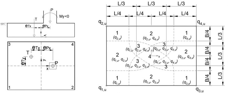
- Uplift - a new dedicated Uplift check is added to those currently performed. For combinations producing tension at the pad base support, the tension value is compared to the stabilizing loads and checked against a factor of safety (FOS). Auto-design can automatically increment the base size to achieve a passing status. For the United States Head code the FOS considered for the uplift check can be specified under Design Options > Concrete > Foundations > Isolated Foundations > General Parameters (default value = 1.50 and now applies also to the sliding check).
- Top Reinforcement Design - for loading which causes tension at the top of the footing, top design moments are now calculated and top reinforcement designed. Previously top reinforcement could be added to a base but was not specifically checked. Top reinforcement can be auto-designed or directly specified and checked in the same manner as for bottom reinforcement.
- Code Coverage - all the above enhancements are made for the BS, Eurocode and United States Head Codes but not the Indian Head code while the new Base Pressure Calculations only are performed for the Australian Head Code.
Concrete Column and Wall Design Enhancements
Additional Design Cases
Reinforced Concrete columns and walls can now be designed for user-defined forces. This feature can be used for example to design for results from Post Tensioning analysis programs. Additional forces are added in the Interactive Design dialog as shown below per selected stack/ panel. Any number of Design Cases can be added and are checked alongside regular combinations.
- Note that factored design values are entered and are used as-is in all design checks - i.e. no additional minimum moment or moment magnification calculations are performed for the cases.
Image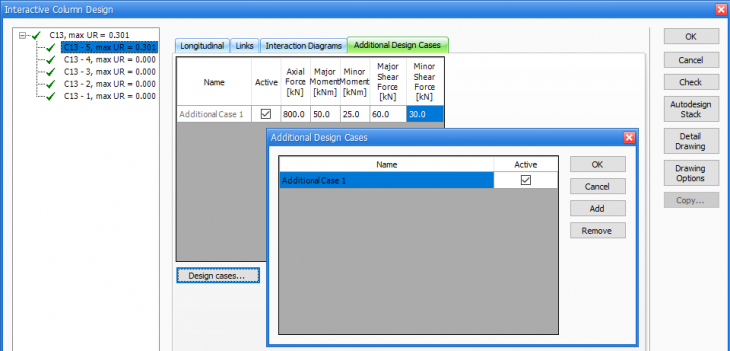
Enhanced Interaction Diagrams
The Interactive Design dialog Interaction Diagrams for both Columns and Walls are now more flexible. Where previously only the critical combination was shown, new controls are added allowing the Moment-Moment diagram to be viewed for any analysis method, combination and position. Where applied the new additional Design cases can also be selected.
- The “Set Critical” button returns to the Critical parameters the results of which are automatically displayed when the Interactive Design dialog is first opened.
Image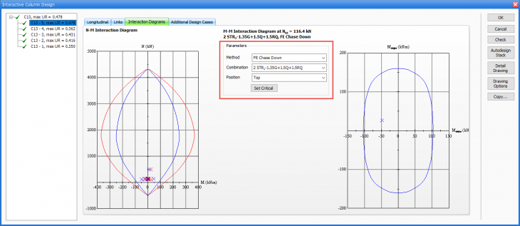
Selective Design Enhancements
In addition to features added in Release 18 and subsequent service packs, it is now possible to design any graphically selected sub-set of a model using the right-click context menu options available after making the selection. This can be particularly beneficial for working with larger models.
- An expanded Help Topic has been added in this release "Working with Large Models" - engineers are encouraged to review guidance in this topic since a range of recently added features offer a more productive workflow during scheme development.
Image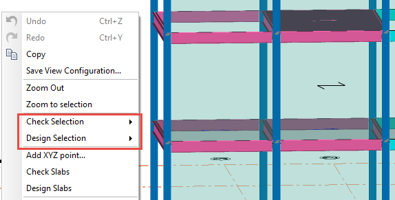
Improvements to Sway and Drift Checks and Controls
Checks for Concrete Walls
Sway and Drift checks are now performed for concrete walls - both meshed and mid-pier - in the same manner as for columns. Just as for columns the check results can be reviewed graphically in the Results View via the ‘Sway Drift and Storey Shear’ controls and via a summary table in Review View > Tabular Data.
Checks Now Run After Analysis
Wind drift checks are now performed when any 3D analysis is run in isolation. If a sub-set of combinations are considered in the analysis then only those combinations will be considered in the drift checks. This feature will allow engineers working on larger structures to investigate and optimize the lateral load resisting systems more rapidly.
Results and Review View Enhancements
- Results View - Drift Results - the Sway, Drift and Storey Shear controls are now rationalized in a similar manner to other graphical result buttons, with all result options listed in a single drop-list.
- Review View - Show/Alter State - Wind Drift results can now be reviewed graphically in the same manner as Sway checks in the Review View via the Show/Alter State command by selecting the “Wind Drift” Attribute and “Review” mode as shown in the picture below. In addition the ‘Sway/Drift check’ Attribute is now removed and replaced with either ‘Sway’ or ‘Drift’ as appropriate to the model Head Code.
Image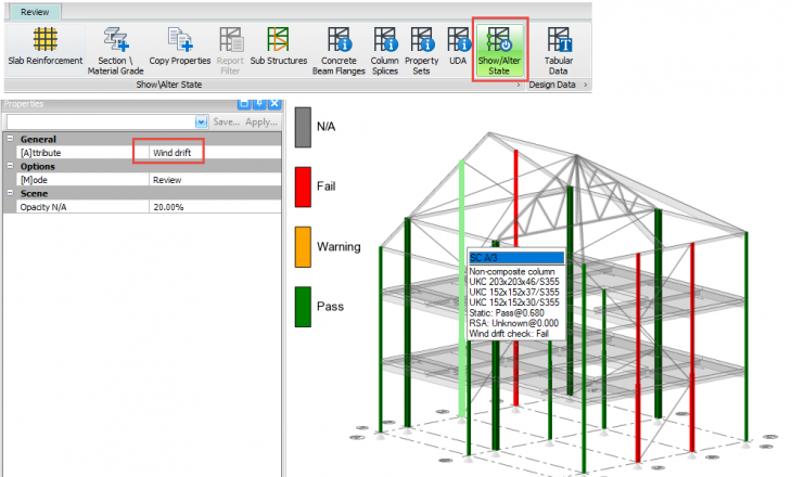
- [54164]1 - Drift, Sway and Seismic Drift - where previously calculations for these referenced only column points at levels with the “Floor” setting checked on, they now reference all column stack points in the same manner as Wind Drift checks. This produces more consistent and logical results and applies to both graphical and tabular Sway/Drift results.
Short Stack Controls
A new Design control “Merge short stacks” is added which automatically merges column and wall stacks to prevent short stacks from producing erroneously critical sway check results. When enabled a user-specified length limit applied to the merging can be set (default 1.0 m/ 3ft). Additionally short single stack columns & walls below the limit length are not checked.
- A new member property gives manual control over individual columns and walls to merge a selected stack with the stack below (this overrides the automatic Design setting when enabled)
Image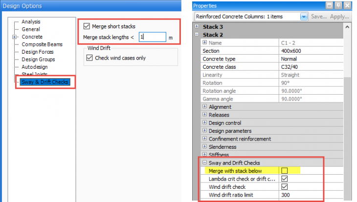
Connection Design
New Integration with IDEA StatiCa
Connections can now be exported to the IDEA StatiCa Connection Design program. For more information about this program please see the IDEA StatiCa website. Connection geometry, section sizes and forces are exported to IDEA StatiCa in which the connection can be designed.
Image
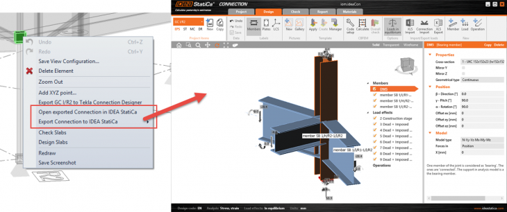
- The link is operated in a similar manner to exporting connections to Tekla Connection Designer; first run the Update Connections command to populate the Project Workspace > Connections list, then right-click a connection and choose “Export Connection to IDEA StatiCa“ from the context menu.
- On completion of the design, the IDEA document can be saved as an external document and\or embedded back in to the Tekla Structural Designer file. A previously exported connection can be reopened from Tekla Structural Designer using the “Open exported Connection…” context menu command.
- For more information on using this feature please see the Help Topic: User Guides > BIM Integration > Export to IDEA StatiCa Connection Design...
- Please contact IDEA StatiCa for all licensing and support queries regarding their program.
Connection Resistance Check Enhancements
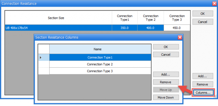
Additional check values, corresponding to different connection types, can now be added to the Connection Resistance Database. Any number of columns can be added for checking. Following a design each value is checked and the critical combination and utilisation ratio reported in the Review View > Tabular Data Connection Resistance Table.
Image
Design - New Design Code Coverage
Australian Head Code
Design of Isolated Foundations to AS 3600-2009
- Concrete Column Pad Base and Wall Strip Footings can now be designed to AS 3600-2009. The scope of design matches that for other country design codes with comprehensive checks of bearing capacity and footing strength for bending and shear.
Slab Design Punching Check to AS 3600-2009
- Punching checks can now be performed on slabs designed to AS 3600-2009. As for other country design codes, the check accounts for the presence of adjacent slab openings.
Indian Head Code
Seismic Loading to IS183 (Part 1): 2016
- IS183 (Part 1): 2016 is added to the Action Codes Seismic Loading options for the Indian Head Code. The Seismic Wizard is fully updated with new settings for this option.
Seismic Design & Detailing to IS 13920: 2016
- Concrete beams, columns and walls forming part of an SFRS can now be designed to IS 13920: 2016. The comprehensive scope includes the following notable features:
- For Seismic Beams, an enhanced maximum width check is performed considering the left and right side projections at each end of a beam following clause 6.1.4 of IS 13920:2016
- The design of seismic cantilever beams is updated following the revised IS 1893 (P1) : 2016, clause 7.12.2.2.
- Seismic Special Shear Walls can be specified and designed to IS 13920 : 2016. Comprehensive checks include that for the design of Boundary Elements to cl.10.4.
United States Head Code
Loading and Design to ASCE7 2016
- ASCE7 2016 is added to the Action Codes available for the United States Head Code. The scope of loading matches that of the existing 2010 versions and includes all of; Loading and Combinations, Snow Loading, Wind Loading, Seismic Loading and the Seismic Wizard. ASCE7 2016 is also added to the Resistance Codes options for Seismic Design and Detailing.
- In addition to the new code coverage, Snow Loading is enhanced to allow multiple drift loads on a single roof panel. Each edge of a roof panel can now be assigned a drift with its own unique properties while a single uniform load is applied to the non-drift area.
Concrete Design to ACI 318-2014
- ACI 318-2014 is added to the Resistance Codes available for USA Concrete Design. The scope matches that of the existing 2008 and 2011 versions for both static and Seismic loading, and applies to all the following concrete elements; Reinforced Concrete Beams, Columns and Walls; Reinforced Concrete Slab Panels, Slab Patches and isolated Punching Checks; Reinforced Concrete Pad Bases, Strip Bases, Pile Caps and Mat Foundations.
Steel Design to AISC 360-2016
- AISC 360-2016 for both ASD and LRFD is added to the Resistance Codes available for USA Steel and Composite Design. This applies to all steel and composite members currently designed and the scope matches that of the existing 2005 and 2010 versions.
- New Sections and Order Lists - the AISC shapes database is also updated with the addition of some new sections - notably several W sections - and some revised section properties. Two new Order Lists are added which include the new sections; “W Shape Beams” and “W Shape Columns”. Both contain all W shapes; in the former all Beam proportioned sections are listed first, while in the latter all Column proportioned shapes are listed first. See the Installation section above for updating your databases and order lists to include these and the new sections.
Loading - All Head Codes
Enhanced Loadcases and Combination Generator
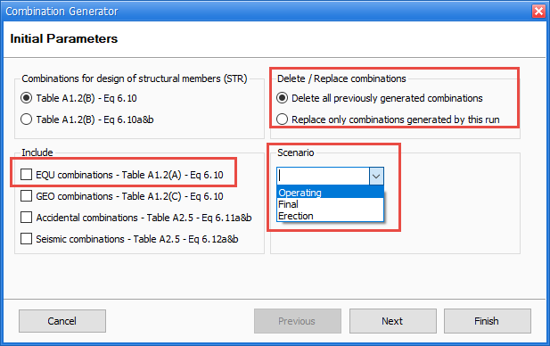
- Retain Combinations - following customer feedback new control enables retention of previously generated combinations. The engineer can opt either to Delete all previously generated combinations (previous behaviour) or replace only the combinations generated during this run.
- New “Scenario” setting - this allows the generation of a series of Combinations for a defined design Scenario – such as “Operating” or “Final”. Any text name can be typed into the Scenario name box and a few suggested values are available by default via the drop-down button. A text string for the Scenario is added to the generated Combination name eg “(Operating) STR1-1.35G+1.5Q+1.5RQ”.
- A new loadcase type “Imposed (other)” or “Live (other)” has been added giving greater flexibility for types and factors for Imposed loads.
Image
Load Groups
A completely new loading concept “Load Groups” is introduced to facilitate the generation of combinations (primarily for design of Industrial Structures where many loading scenarios must be considered). Key operational points/ features are:
- Load Groups are an aid to building Combinations - both manually and using the Generator - and their use is entirely optional.
- Once a Combination is built using Load Groups, the link to the Load Group is lost – the Combination is made up only of Loadcases. Only Loadcases and Combinations are analysed – Load Groups are not.
- Each Load Group holds items of a single load type - e.g. “Dead” or “Live”...etc. - and can contain both multiple load cases and other Load Groups.
- The fundamental Load Groups setting is the “Class” which is either “Inclusive” or “Exclusive”:
- When “Inclusive” – all loadcases are added at once into a combination.
Image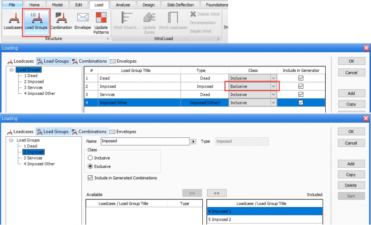
- When “Exclusive” – loadcases are used one at a time in combinations. Thus for example, where an Exclusive Load Group contains four load cases, the Generator will produce four combinations for all required combinations which include the group’s load Type (e.g. “Imposed”), each containing only one of the group’s four cases.
- When “Inclusive” – all loadcases are added at once into a combination.
Imposed Load Reductions for Beams
US Head Code
Where formerly imposed load reductions were considered for one-span, pin ended, steel beams only, they are now considered for all steel and concrete beams*. Reduced forces are calculated by a highly sophisticated and possibly unique automatic determination of the total supported floor area which inherently takes account of supported columns/walls.
- *Except beams that are rotated (major axis not horizontal).
All Other Head Codes
For concrete beams, the level of imposed load reductions to consider can now be defined manually in beam properties and reduced forces are then considered in the beam design. The reduction is entered as a percentage consistent with the existing method of defining imposed load reductions for slabs/ mats. This is especially useful for more economic design of transfer beams supporting a number of floors.
Loading - Country/ Code Specific
Eurocode (All NA’s) - New Equilibrium Combinations
A new option is included to generate a set of 3 Equilibrium Combinations. The ψ0, ψ1, ψ2 factors for all loadcase types are exposed to the user for review/ editing.
Image

Malaysia Eurocode - Seismic Loading to 2017 NA for EC8
A new NA for EC8 for Malaysia is added for MS EN 1998 – 1 : 2004 + A1:2013 (EC8) with the Malaysia NA – 2017, which is more in line with the Eurocode. The previous option is also retained for loading to MS EN 1998 – 1 : 2004 + A1:2013 (EC8) with the Malaysia NA – Draft for Public Comment 2016. The selection of NA to use is made via the Seismic Wizard as shown in the picture below.
- For the new 2017 NA option a new “Soil Deposit” selection is added. As previously three regions are listed for selection; Peninsular Malaysia, Sarawak and Sabah. The reference peak ground acceleration no longer has a fixed value: it is now user-defined following reference to Annex B of the NA.
Image Image
Image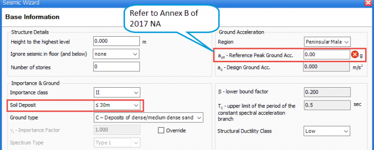
BIM Integration
Improved workflow with Tekla Structures
When the project is begun in Tekla Structures we recommend using the Analytical Model link to Tekla Structural Designer which has been improved as follows:
- Curved beams and PolyBeams - these are now exported provided the “Use curved member” option is selected in the Properties for the Tekla Structures analytical model.
- Get Results - this command can be used to update Section Sizes and Material Grades of members and any changes are listed in the Model Comparison Tool for review/ acceptance.
New Integrator for Revit 2019
A new version of the Revit Integrator which supports Revit 2019 is now available from Tekla Downloads. This incorporates a number of fixes and enhancements to previous releases for other Revit versions. Updates incorporating these are also available for the Integrators for Revit 2017 and 2018.
Improved Section & Material Mapping
We are continually expanding the range of sections and materials that are mapped during Integration with both Tekla Structures and Revit. This requires updates to all parts of the integration ‘chain’; the BIM application (e.g. Tekla Structures), the Integration Tool where applicable (e.g. the Revit Integrator) and Tekla Structural Designer. Improvements have been made for the following regions:
Australia
- Required updates made in Tekla Structural Designer 2018.
- Required updates made in Revit Integrator 2019 and recent updates for Revit 2017 & 2108.
- Required updates partially complete in Tekla Structures - the users can manually create mapping files for any problem sections.
India
- Required updates made in Tekla Structural Designer 2018.
- Required updates made in Revit Integrator 2019 and recent updates for Revit 2017 & 2108 (except Sail Sections).
- Required updates partially complete in Tekla Structures - the users can manually create mapping files for any problem sections.
Modelling and Review
User Points
User defined points can now be created anywhere in the model without requiring the use of either grid or construction lines. Any entity can then be created using these point(s). This facilitates creating members with points not defined by the main grids/levels such as cantilevers or gable posts.
- Points are defined by three global X, Y and Z coordinates and are added either via the Scene right-click context menu “Add XYZ Point…” command or a new dedicated dialog opened via the new Edit > “XYZ Points...” button which lists all currently defined points. A separate control is added to Scene Content settings for their visibility.
Image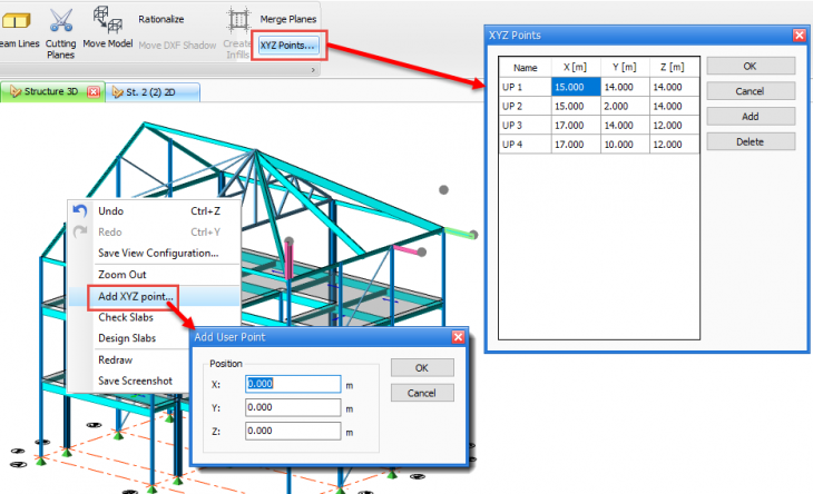
Review View Enhancements
- BIM Status and UDAs - a new Characteristic filter is added to available settings when reviewing BIM Status and UDAs making the feature more practical for larger models and/ or large numbers of UDAs.
Image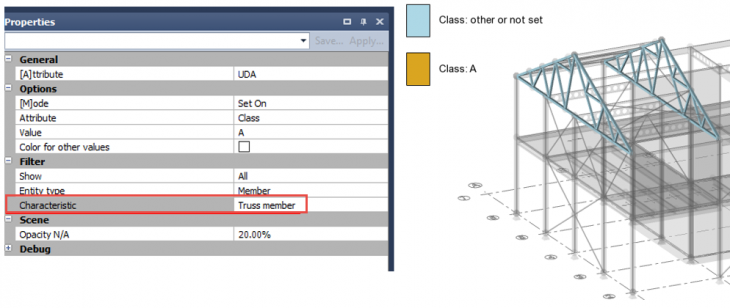
- Copy Properties - a new option to copy All properties is added to the existing attributes for this command. This can be applied to all members, Walls and Slab panels, and copies all properties that can be included in a property set.
Image
New Member Alignment Controls
Improvements are made to member alignment settings enabling better definition of, for example, offset bracing connections as shown in the picture below.
- These alignment settings affect only the member’s graphical representation, so are reflected in drawings but not in the analysis model. They apply to steel members only with the following characteristics; Beams, Braces and Truss Members.
- Previously offsets could be applied only at each end relative and lateral to the member insertion line. Now a single offset is made to the member as a whole - for either or both axes - while unique Global offsets (in terms of X, Y and Z dimensions w.r.t. the insertion line points) - can be applied to either end. This brings the method of line element alignment in line with that used in Tekla Structures.
Image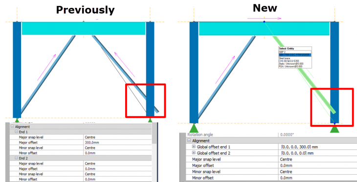
Fixes & Minor Enhancements
General & Modelling
- Performance and Stability - a number of fixes and enhancements are made to improve general program stability and performance.
- In particular, on larger models you may notice some significant improvements to display speeds in the Results View.
- BIM Integration:
- Improved handling of Holes in Walls:
- [TSD-1366]1 - IFC Export - holes were exported, but due to a defect for some models, they were not located correctly and hence did not display after importing the IFC file into Tekla Structures or the Free Solibri Model Viewer for example. Holes are now exported correctly.
- [SRX14428]1 - Revit Integrator - an error in the export Wizard which prevented holes in walls from being exported correctly is now fixed.
- [TSD-1384]1 - Walls - Copying - from 2018 SP1 (version 18.0.1.10 released in April 2018) and later service packs, using the Copy command on structural walls would have caused problems for BIM because the internal reference used for round-tripping was duplicated in error. Other model objects were not affected in the same way. Opening a model with duplicate references in this new release will generate unique references for each copy as well as preventing the problem occurring if the Copy command is used again.
- Improved handling of Holes in Walls:
- [TSD-697]1 - Delete - in line with customer feedback, Select all/ Unselect all buttons are added to the filter dialog displayed when the Delete command is invoked for a selection of multiple entities.
Image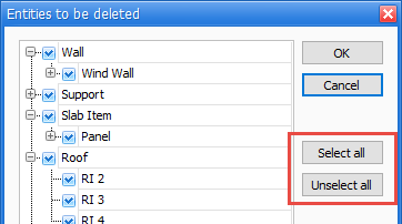
- [TSD-795]1 - Centre of Rigidity (CoR) - the approximate centre of rigidity (identified by a red graphical arrow with “Centre of Rigidity” option checked on in Scene Content settings) did not correctly account for the fixity of columns causing pinned columns to be included as if fully fixed. Now only columns fixed at both ends are included when calculating the approximate CoR.
- [TSD-271]1 - Connections - References - the “Start Level Reference” option is added to those available for the Reference Format for Connections. Thus for example a number of Beam to Column connections on the same column can all be assigned a unique reference which includes the connection level where previously, they would have had an identical reference.
- Note that the new Format item is not included by default so must be set via Home > Settings > References > Formats for new models and Home > Model Settings > References > Formats for existing models. Existing connections must then be deleted and the “Update Connections” command run again to reflect the Reference format changes.
Image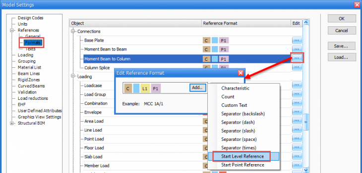
- Note that the new Format item is not included by default so must be set via Home > Settings > References > Formats for new models and Home > Model Settings > References > Formats for existing models. Existing connections must then be deleted and the “Update Connections” command run again to reflect the Reference format changes.
Loading
- [TSD-629]1 - Load Decomposition - Wind Panels - the Wind Panel option to decompose to Rigid Diaphragms now functions for manually applied panel area loads. Previously the setting functioned only for wind loads applied by the Wind Wizard and manually applied panel area loads were ignored (which would be flagged by an error status for the Load Summary check of Total User Applied load vs Total load on Structure).
- When applying manual area loads for wind loading the “Normal” direction option should be used. Also ensure that the correct sign is used appropriate to the desired direction - the graphic of the applied load confirms this.
- [TSD-180]1 - Load Combinations - Import - load combinations defined in an Excel spreadsheet can now be imported via the Load Combinations dialog. For more information on using this feature please see the Help Topic: User Guides > Loading Guide > Working with Combinations > How do I import loadcases and combinations from a spreadsheet?.
Validation
- [TSD-321]1 - Single Angles - a new Validation check and associated Warning is added for moment releases applied to beams with single angle sections to assist engineers with ensuring releases are applied as they intend - for more information see the Help Topic Engineer's Handbooks > Analysis Handbook > Releases > Note on single angle releases.
Analysis & Results
- Results View - Deflections - following user requests, deflection results are now given for additional nodes at the mid-points of members in the 1D deflection diagrams. When activated, numerical values are also displayed at these nodes. For all node points a tooltip is added which displays deflection values for all directions when nodes are cursored over and nodes are identified by graphical points making their location clearer.
- [TSD-186]1 - Trusses - Internals - when the Tension only property was activated for truss internals they would still have compression stiffness and hence could develop compression forces. The solver element of truss internals is now correctly set to the tension only type producing the correct behaviour provided non-linear analysis is run.
- [TSD-446]1 - Tabular Data - Vibration Analysis - Total/ Active Masses by node - the columns for rotational mass are removed from these reports as the previously reported values were not meaningful/ useful. This change is also reflected in the associated report items.
- [TSD-630]1 Analysis Model - Semi-Rigid Diaphragms - Default mesh size - the default maximum mesh size has been increased from 1m to 2m (Metric Units) 3'6" to 8' (US Customary Units). It has been observed that using refined meshes generally has negligible impact on results and only has the effect of slowing down analysis and increasing memory requirements. It is suggested that even the revised defaults may be more refined that is actually necessary. The change will only affect new models, the benefits of using a less refined mesh in existing models can be obtained by adjusting the relevant mesh parameters. Engineers working with larger models are recommended to consider the "Working with Large Models" advice in the help system.
- [TSD-321]1 - Single Angles - the handling of moment member loads in the analysis of steel beams with single angle sections is addressed to correct the direction of load application and yield more expected results. In addition, as noted above, a new Validation check and associated Warning is added for moment releases applied to such beams to assist engineers with ensuring releases are applied as they intend - for more information see the Help Topic Engineer's Handbooks > Analysis Handbook > Releases > Note on single angle releases.
- [TSD-630]1 - Settings Sets - United Arab Emirates (UAE) - in the UAE Settings set, the Analysis Options > Modification Factors > Concrete values defaulted to those following Eurocode guidance. They are now updated to default factors more appropriate for the ACI head code.
- The updated values will automatically apply to new models. Existing models can be updated by first ensuring that the UAE Settings set is active, then updating the model settings via Analyse > Options and clicking the [Load…] button.
Design
General
- [TSD-525]1 - Concrete Design - Concrete Walls - Shear Links(Stirrups) - an erroneous fail status and message “Supplied links/ stirrups are not sufficient” could be issued in design details where no shear reinforcement was required and the interactive design setting “Use links” was set to off. This was caused by shear link spacing checks still being performed. It could be worked around by enabling “Use links”, setting a passing link spacing, then checking off “Use links” again. This issue is fixed in this release and the workaround is no longer required.
Head Code US
- [TSD-161]1 - Concrete Slab/Mat Design - Punching checks - changes are made to the assumption of how the slab punching shear critical perimeters for circular and polygonal columns are obtained. Where previously these were obtained by considering as the starting point the bounding rectangle of the column section, now a rectangle of equivalent perimeter length to the column section is used as the starting point. This results in a design which is both more conservative and in line with the design code assumptions.
- [TSD-1267]1 - Concrete Beam Design - Shear Link Spacing - the max spacing of link legs across a beam defaults to 12" but was limited to 40". Unlike other design codes, ACI 318 does not specify a limit and so this upper limit in increased. However, attention is drawn to an ACI Structural Journal Technical Paper - “Shear Reinforcement Spacing in Wide Members”, which suggests a limit of around "d".
Reports & Drawings
Reports
- Analysis Report Items - the following improvements are made to a number of analysis reports:
- [TSD-402]1 - Nodes - a new Analysis Method filter is added for the Nodes report item allowing all of the nodes in a particular analysis method model to be reported. This allows for example reporting of the 2D mesh nodes where formerly this was not possible.
- [TSD-424]1 - Vibration Analysis Reports - Node data - new columns for node coordinates and diaphragm reference are added to the following reports; Mode Shape, Total Masses by Node and Active Masses by node. This facilitates further processing of this data after export to Excel for example.
- [TSD-445]1 - Total/ Active Masses by node - Simple Mass Option - for engineers who wish to calculate values such as centre of mass for each floor using these report items, a new simple mass option is added to simplify the calculation. When checked on, a single value of mass is reported for each node rather than values for each analysis direction. However, it is recommended that the new simple mass option is enabled only when the Lumped Mass Model option is used for Vibration Mass.
- [TSD-1083] - Loading - Snow Loads - in models with Snow Load cases generated by the Snow Wizard, the report would fail to generate when the Loading item was included and the applied filter caused the inclusion of any of the generated Snow cases. Hence it was not possible to output snow load case Loading data. Generated Snow Load case data can now be included in report using the Loading item.
Footnotes
1 This number is an internal reference number and can be quoted to your local Support Department should further information on an item be required.