Guide to resolving Mechanisms
Not version-specific
Tekla Structural Designer
Environment
British Standard
Eurocode
Mechanisms are stability problems in the model which must be addressed and we advise should not be ignored. More information related to mechanisms can be found in the related (N-1) rule article. The N-1 rule must be followed when modelling to avoid these warnings.
Mechanisms can be classed into two main types:
- Local - a node that is free to spin in one or more DOF's, or a member that is free to spin about its longitudinal axis. DOF = Degree of freedom, i.e. a direction of translation or rotation. In a 3D model, there are 6 DOF's at every node; X, Y and Z translation and X, Y and Z rotation.
- Global - a member or arrangement of members that are free to fall over or displace indefinitely in one or more DOFs.
Examples of Local mechanisms are:
- A column with a pinned base support and also a pinned bottom end, leaving the end joint free to spin
- A column with a fully pinned base support (Mx, My and Mz free) with all attached/ supported members (e.g. beams) also pin-ended. The column is free to spin about its longitudinal axis
- A beam with a pinned end support and also a pinned end, leaving the end joint free to spin
Examples of Global mechanisms are:
- A member not connected to any other member or support that is just 'floating' in space.
- A free-standing column with a pinned support that can therefore just fall over in any direction
- A 2D frame (e.g. a simple 'goal post') with fully pinned supports that has no members connected to it out of plane and that can therefore just fall over sideways (out of plane).
- An unbraced building with all beam/ column connections pinned and no other form of lateral force-resisting system.
Status Tree - Solver Mechanism Warnings
Mechanisms will be flagged by Warnings listing affected nodes in the Status Tree > Solver group - as shown in the picture below. They will commonly be accompanied by additional warnings for excessive deflections. To locate the affected nodes; activate the Solver view then double-click a warning or group of warnings.
When double-clicking on a Mechanism warning, the most affected node will be highlighted with a blue arrow as shown below; often this is the single node the stability of which needs addressing, however sometimes it is just the most affected or first encountered during solution and further investigation is required (i.e. deflections or visual interrogation of the releases via Review view)
Image

Things to consider
Changing the Releases on the members
The issues you are encountering can often be resolved by changing the Releases on the members as appropriate; thus achieving the N-1 rule. Releases can be changed by selecting the member and scrolling to Releases in the Properties window.
Image

Turning on Members>Direction for the Structure view Scene Content shows a pink arrow next to each member, pointing from End 1 to End 2, as shown above.
Image

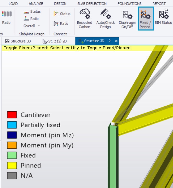
Releases can also be changed using the Fixed/Pinned review tool in the Review view.
Note that this tool will only allow you to toggle between Fixed, Pinned, and Moment releases with the Fixed/Pinned Attribute set. A Free (cantilever) end can also be set using the "Cantilever End" Attribute as described in the Tekla Structural Designer 2019i SP2 Release notes here (General & Modeling section).
Image
Turning on 1D Elements>Releases for the Solver view Scene Content is useful for viewing the releases applied graphically.
Image

Image

Redundant releases
Sometimes Tekla Structural Designer will point to the middle of a member, this means that there are redundant releases at one or both of the supports of that member.
Cantilever beams
Cantilever beams must be set as Cantilever end ("Free end" in earlier versions) on the cantilever side, regardless of whether they have another member connected to them or not. Bear in mind that Composite beams cannot currently be set as cantilevers (since they cannot be designed for hogging moments) hence set cantilevers to non-composite.
Also note that two cantilever end releases cannot be connected so only one of the two members must be set as cantilever.
1st Order Modal Analysis
Mechanisms can often be located by running a 1st order vibration analysis. Mechanisms will present as modes which have a frequency of zero. This is because a mechanism by its very nature has zero stiffness and hence can displace indefinitely in one or more DOF's. Frequency is fundamentally related to stiffness and mass - in fact to sqrt(k/M) where k = stiffness and M = mass. So when k = 0, you have frequency f = sqrt(0/M) = 0.
To carry out a Vibration analysis, create a Modal Mass combination - we recommend you include the gravity cases in this combination.
Image

This can be a faster analysis and can help you to locate some mechanisms. Animate the modes with frequency of zero and they can be apparent e.g. a cantilever with a pinned root will 'flap' up and down or side to side (*note that this will not be the case with a local mechanism however since the mode shape cannot represent nodes or members spinning).
Running vibration analysis is not a 'panacea' however for finding mechanisms - if mechanisms are too severe or extensive it may simply fail to solve.
Providing it runs, once the process of finding and resolving mechanisms using vibration analysis is complete, 1st order linear can then be run to find further possible mechanisms.
Once Vibration Mass and 1st order vibration analysis yield no mechanisms you can run 1st order non-linear analysis and resolve any further mechanisms found, if any.
We recommend that close attention is paid to the nature of the mechanisms. This may help you in resolving a number of them before re-running analysis. For example, if Tekla Structural Designer prompts that mechanisms are found on pinned beams connecting to pinned columns (redundant releases) then there is a chance that this scenario will be repeated in other areas. By using the above advice, you can spot redundant releases by navigating through the model.
Another scenario, for example, is where a cantilever beam is not set as cantilever (which is incorrect modelling from both a design and analysis perspective). If this mistake has been made on one cantilever beam it may have been made on many (Tekla Structural Designer will point to the most critical one).
The above process should be performed iteratively until the analysis solves to a green tick mark.
Image
