Improvements in components
There are several improvements in concrete components and steel components in Tekla Structures 2023.
Tekla Structures 2022 service packs also introduce improvements to components, see:
Improvements in component update performance
Component update performance has now been improved in hierarchical cases, where the objects created by a component are used as input objects for other components. For example, the Wall layout component creates wall panels, which are then used as input objects for reinforcing or other detailing components. Previously, the update of the main component could trigger multiple updates of each detailing component, which caused slowness in the operation. This has now been improved by removing the unnecessary update calls.
Concrete components
| Component | Description |
|---|---|
|
Border rebar for single edge (93) |
Border rebar for single edge (93) has many improvements in Tekla Structures 2023:
|
|
Floor layout, Wall layout |
|
|
Geometry detailing strip |
The new Extend detailing strip option allows detailing strips to be extended over the whole part face when the geometry detailing strip is created as a single line. Setting the Extend detailing strip option to Yes will extend and fit the detail in both directions of the input line to the edge of the applied face. This provides more flexibility for the use of the tool. Detailing strips created within the wall layout are automatically extended. Previously, not all detailing types were extended in the wall layout connector. Now this issue has been fixed, which means that inner corners created with Wall layout work correctly for all detailing types from the geometry detailing strip. |
|
Slab bars (18) |
In Tekla Structures2023, the Slab bars (18) component is no longer available in the Applications & components catalog. You can use the Mesh bars and Mesh bars by area components to create reinforcement to concrete slabs or walls. |
|
Lifting anchor (80) |
Lifting anchor (80) now supports rebar assemblies as input objects. This allows you to create lifting anchors directly on rebar assemblies. For example, meshes or cages can now easily get anchors based on their center of gravity. Note that the distribution of the anchors is based on the main bars in the rebar assembly. |
|
Tapered I beam (81) |
|
|
Rectangular area reinforcement (94) |
|
|
Sandwich wall window |
In Sandwich wall window creation, the handling of input points has been improved. The window is now created in the correct location regardless of the order in which the input points are picked. The options for setting window dimensions have been renamed as follows:
The Sandwich wall window component instances created with previous Tekla Structures versions work as before. |
|
Wall to wall connection |
On the Edge shape tab, two new uneven wall edge shapes are now available. |
|
Start number for reinforcement in system components |
Previously, when you defined a negative start number for reinforcement in system components, the prefix was removed and the start number was set to 1. This issue has now been fixed. It is possible to use a negative start number for reinforcement in system components. |


Steel components
| Component | Description |
|---|---|
|
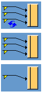
Turnbuckle bracing (S7) |
On the Connection tab, you can now select to use the Tensioner (7) component as the connection type. |
|
Bracing cross (19) |
You can now define the bolting direction on the Bolts tab. |
|
Tube gusset (20) |
You can now define the bolting direction on the Gusset conn, Brace bolts 1-3, and Cross plates tabs. |
|
Pipe column and beam panel zone (21) |
On the Panel parts tab, you can now use Taper profile orientation to change the preferred direction of plates if the tapering type of the short column is Buildup. |
|
Tube crossing (22) |
You can now define the middle end plate properties on the Brace conn tab. |
|
Shear plate full depth special (39) |
You can now define the cope cut depth and length separately on the Picture tab. You can also select whether cope cut sizes are checked using the Allow partial cut in fillet radius option.
|
|
Stiffened shear plate (17), Haunch (40), Corner bolted gusset (57), Wraparound gusset (58), Hollow brace wraparound gusset (59), Wraparound gusset cross (60), Windbrace connection (110), Bent plate (190), Base plate (1004), Stiffened base plate (1014), Web stiffened base plate (1016), Base plate (1042), U.S. Base plate (1047), Circular base plate (1052), Cage ladder (S60) |
You can now specify the Finish property for parts. |
|
Diagonal splice (53) |
|
|
Corner tube gusset (56), Corner bolted gusset (57), Corner gusset (63) |
On the Gusset tab, you can now define a chamfer in the inner corner of the gusset plate.
|
|
Splice type 1 (56) |
You can now define the bolt properties, slotted holes, bolt assembly, and bolt length increase separately for the main part and secondary part bolts. |
|
Cage ladder (S60) |
|
|
Tube column splice (65) |
On the Parameters tab, you can now control the shear tab side for each face. |
|
HSS Brace Special (66), HSS Brace Special (67) |
|
|
Stairs (S71), Wooden steps pan (S72), Polybeam pan (S73), Z pan (S74) |
On the Picture tab, you can now define the vertical offset for the left and right horizontal landing at the top and bottom of the stringers. |
|
Railings (S77) |
On the Bends tab, you can now define the cut distance along the rails separately for the right and left rail end. |
|
Two sided end plate (142) |
You can now define the bolting direction on the Bolts tab. |
|
Clip angle (141), Two sided clip angle (143), Shear plate simple (146), Angle profile box (1040) |
On the Angle box tab, you can now define the bevel cut offset from the start or end for triangular angle box stiffeners. For Angle profile box (1040), you can define the offset on the Parameters tab.
|
|
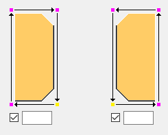
End plate (144), Shear plate simple (146) |
On the Notch tab, you can now select that the notch size is measured from the edge of the main beam flange and from the outer edge of the top flange of the main beam.
|
|
Joist to column, type 1 (161), 2-Sided joist to column (162) |
On the Plate or Cap plate tab, you can now specify the width and length of the cap plate by defining the offsets from the main part edge.
|
|
Joist to column, type 2 (163) |
|
|
Central gusset (169) |
You can now define the bolting direction on the Brace bolts 1 - 4 tabs. |
|
Full depth S (185) |
On the Plates tab, you can now define a gap between the secondary part web and shear tab for connections that have only one shear tab. |
|
Bent plate (190) |
On the Bolts tab, you can now define the number of welds created between the bent plate and secondary part, and the bent plate and main part.
|
|
Base plate (1004) |
You can now define a bolt comment on the Bolts tab. |
|
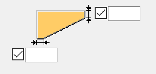
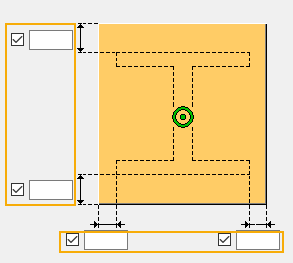
Multiple stiffeners (1064) |
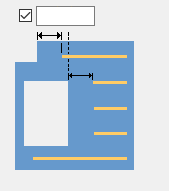
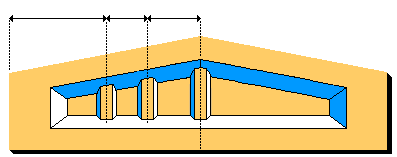
It is now possible to rotate the stiffener polygons on the Parameters tab.
The value you enter determines the number of points by which the start point of the polygon is moved in the direction shown by the arrows. |