Multiple stiffeners (1064)
Multiple stiffeners (1064) creates multiple stiffeners to I, C, and U profiles.
Objects created
-
Stiffeners
-
Welds
Use for
| Situation | Description |
|---|---|
|
|
Multiple stiffeners created to an I beam. |

Selection order
-
Select the main part (beam or column).
-
Pick a position for the stiffeners.
The stiffeners are created automatically when you pick the position.
Part identification key

| Description | |
|---|---|
|
1 |
Stiffener |
Picture tab
Use the Picture tab to define the number and spacing of the stiffeners.
Stiffeners

| Description | |
|---|---|
|
1 |
Number of stiffeners. |
|
2 |
Stiffener spacing. Use a space to separate stiffener spacing values. Enter a value for each space between stiffeners. For example, if there are 3 stiffeners, enter 2 values. |
Stiffener creation direction
| Option | Description |
|---|---|
 |
Default Middle AutoDefaults can change this option. |
 |
Middle Creates stiffeners symmetrically. |
 |
Right Creates stiffeners to the right of the up direction symbol. |
 |
Left Creates stiffeners to the left of the up direction symbol. |
Stiffener offset location
| Option | Description |
|---|---|
|
|
Default Middle AutoDefaults can change this option. |
|
|
Middle Sets the offset to the middle of the stiffener. |
|
|
Left Sets the offset to the left side of the stiffener. |
|
|
Right Sets the offset to the right side of the stiffener. |


Parts tab
Use the Parts tab to define the part properties.
Parts
| Part | Description |
|---|---|
|
Left stiffener |
Thickness and width of the left stiffener. |
|
Right stiffener |
Thickness and width of the right stiffener. |
|
Option |
Description |
Default |
|---|---|---|
|
Pos_No |
Prefix and start number for the part position number. Some components have a second row of fields where you can enter the assembly position number. |
The default part start number is defined in the Components settings in . |
|
Material |
Material grade. |
The default material is defined in the Part material box in the Components settings in . |
|
Name |
Name that is shown in drawings and reports. |
|
|
Finish |
Describes how the part surface has been treated. |
Parameters tab
Use the Parameters tab to define the stiffener angles, creation direction, and offset.
Stiffener angles

| Description | Default | |
|---|---|---|
|
1 |
Angle of the right stiffener. |
0 degrees |
|
2 |
Angle of the left stiffener. |
0 degrees |
Rotate stiffener polygon
Set the stiffener polygon rotation of the right and the left stiffener.
The value you enter determines the number of points by which the start point of the polygon is moved in the direction shown by the arrows.
Fit stiffeners with flanges
Select whether sloped stiffeners are fitted with the main part flanges.
Apply gaps in the coordinate system of
Select whether gaps are applied in the stiffeners or in the main part.
Stiffeners tab
Use the Stiffeners tab to define stiffener creation, dimensions, and chamfers on both sides of the part.
Stiffener creation
| Option | Description |
|---|---|
|
|
Default Full stiffener AutoDefaults can change this option. |
|
|
Full stiffener |
|
|
Partial stiffener, upper end |
|
|
Partial stiffener, lower end |
|
|
Partial stiffener, bevel |
|
|
No stiffeners are created. |


Stiffener dimensions

| Option | Default | |
|---|---|---|
|
1 |
Stiffener edge distance from the beam edge. |
0.0 mm |
|
2 |
Stiffener edge distance from the beam web. |
Beam rounding radius 1 |
|
3 |
Stiffener edge distance from the beam upper flange. |
0 mm |
|
4 |
Stiffener edge distance from the beam lower flange. |
0 mm |
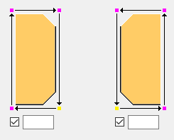
Chamfer type
You can select the chamfer type in each stiffener corner. The default type depends on the stiffener corner.
| Option | Description |
|---|---|
|
|
Default No chamfer AutoDefaults can change this option. |
|
|
No chamfer |
|
|
Line chamfer |
|
|
Convex chamfer |
|
|
Concave chamfer |
|
|
Square chamfer |


Chamfer dimensions

| Description | |
|---|---|
|
1 |
Horizontal chamfer dimension. |
|
2 |
Vertical chamfer dimension. |
General tab
Click the link below to find out more:
Design type tab
Click the link below to find out more:
Analysis tab
Click the link below to find out more:
Welds
Click the link below to find out more: