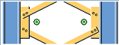
Tensioner brace and compression bar (13)
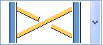
Tensioner brace and compression bar (13) creates one or two bracing crosses between two columns or beams. It is possible to add compression bars between the main parts. You can add connections between the main parts and the bracing crosses, and between the main parts and the compression bars.
Because you can use other components inside Tensioner brace and compression bar (13) to create the connections between parts, the component has a hierarchical component structure. Tensioner brace and compression bar (13) is on the highest level in the component hierarchy (level 0) and the connections are on a lower level (level 1) in the component hierarchy.
Objects created
- Bracing (1 or 2)
- Compression bars (optional)
- Connections between main parts and bracing
- Connections between main parts and compression bars
- Connections in bracing crosses
Use for
| Situation | Description |
|---|---|
|
|
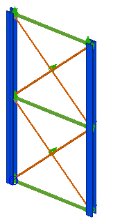
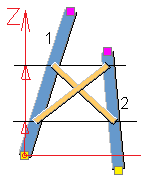
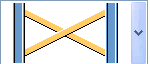
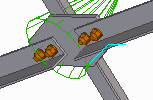
Two bracing crosses and three compression bars with connections. |
|
|
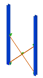
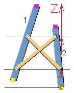
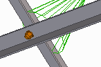
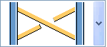
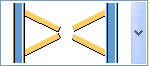
One bracing with connections. |
|
|
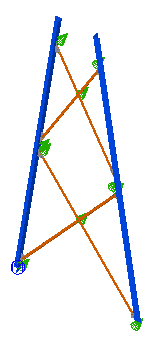
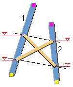
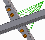
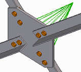
Tapered main parts (mast construction) and two bracing crosses with connections. |
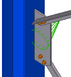
Selection order
- Select the first main part (column or beam).
- Select the second main part (column
or beam).
The component is created automatically when the secondary part is selected.
Picture tab
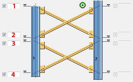
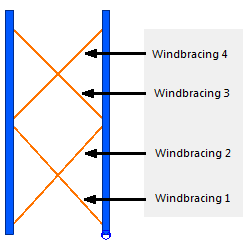
Use the Picture tab to control the bracing levels.
Bracing levels
| Description | |
|---|---|
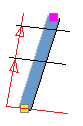
| 1 | Top level of the upper bracing. If no value is entered, the top bracing is not created. |
| 2 | Bottom level of the upper bracing. If no value is entered, the top bracing is not created. |
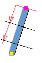
| 3 | Top level of the lower bracing. |
| 4 | Bottom level of the lower bracing. |
Bracing reference
For both main parts, define the reference of the bracing levels. The reference can be set for both the horizontal and the vertical direction.
For example:
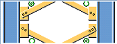
Bracing offset
Define the offset perpendicular to the bracing. You can move the created plate or part by entering a value in the x-, y, or z-direction.
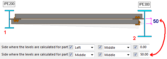
In the example below, the main parts have unequal dimensions and the reference is set to Middle. To create the bracing crosses horizontally, an offset must be entered for the biggest part. The needed offset is the height difference between IPE200 and IPE300, divided by 2 = 50mm.
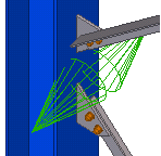
Bracing direction
| Option | Description | ||
|---|---|---|---|
| Direction | Select the direction of the bracing. |
|
Start point of the main part as the reference point. |
|
|
End point of the main part as the reference point. | ||
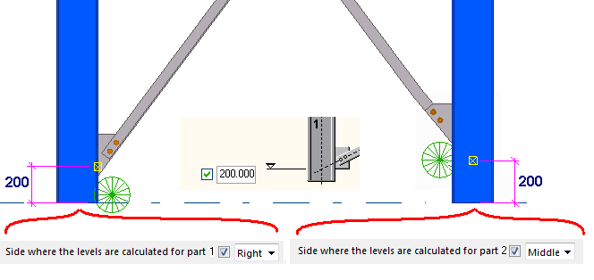
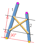
| Calculation of levels | Select the reference line used for positioning the bracing when the main parts are not parallel. |
|
Offset from the start point in part 1, perpendicular to the line through the start points. |
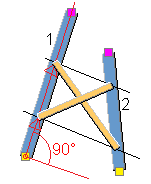
|
|
Offset from the start point in part 1, in local x-direction. | ||
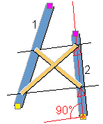
|
|
Offset from the start point in part 2, in local x-direction. | ||
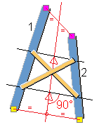
|
|
Reference line through the start and end points of the main parts, offset from the start of the reference line. | ||
|
|
Offset from the start point in part 1, in z-direction. | ||
|
|
Offset from the start point in part 2, in z-direction. | ||
|
|
Freely defined values. | ||
Parts tab
Use the Parts tab to control the properties, bracing position, and rotation. Additionally, you can define bracing splitting and shortening values.
| Option | Description | ||
|---|---|---|---|
| Windbracing
|
Define the bracing profile by selecting it from the profile catalog. | ||
| Windbracing position in plane |
Set the position in plane for the first and the second bracing element. |
||
| Windbracing rotation |
Select the rotation for the first and the second bracing element. This option is useful when the bracing elements are crossing and they are connected in the crossing. |
||
| Windbracing translation |
Select the offset of the first and the second bracing element from the reference points. This option is useful when the bracing elements are positioned so that the first bracing is alongside the second bracing. Typically, the first bracing element is set to Forwards and the second bracing element to Backwards. |
||
| Splitting the diagonal bracing |
Select whether the diagonal bracing elements are split or connected with a component. Define the connecting component on the Joints tab by typing the number of the component in the Connect diagonals with joint number box. |
Bracing is not split. Possible component for connecting the diagonal bracing: Seating (30). |
|
|
First diagonal bracing element is split. Possible component for connecting the diagonal bracing: Bolted gusset (11). |
|
||
|
Second diagonal bracing element is split. Possible component for connecting the diagonal bracing: Bolted gusset (11). |
|
||
|
Both diagonal bracing elements are split. Possible component for connecting the diagonal bracing: Central gusset (169). |
|
||
| Connecting bracing crosses |
Select whether the gusset plates of two bracing crosses above each other are connected. Define the connecting component on the Joints tab by typing the number of the component in the Connection number box. |
Bracing crosses are connected with a gusset connection. Possible component for connecting the diagonal bracing: Bolted gusset (11). |
|
|
Bracing crosses are not connected. Separate connection is created for each diagonal bracing. Possible component for connecting the diagonal bracing: Bolted gusset (11). |
|
||
| Distance between windbracings |
Define the distance between bracing elements. If the bracing elements are crossing each other, this value typically defines the gusset plate thickness. |
||
| Shorten windbracings |
Define how much the bracing are shortened. The entered value is written in the user-defined attributes of the bracing. The value is used in drawings. |
||
|
Option |
Description |
Default |
|---|---|---|
|
Pos_No |
Prefix and start number for the part position number. Some components have a second row of fields where you can enter the assembly position number. |
The default part start number is defined in the Components settings in . |
|
Material |
Material grade. |
The default material is defined in the Part material box in the Components settings in . |
|
Name |
Name that is shown in drawings and reports. |
|
|
Class |
Part class number. |
|
|
Finish |
Describes how the part surface has been treated. |
Compression bar tab
Use the Compression bar tab to define the compression bar properties.
| Option | Description |
|---|---|
| Compression bar |
Define the compression bar thickness, width and height. |
| Create bar | Select whether the compression bar is created.
You can define up to three compression bars. |
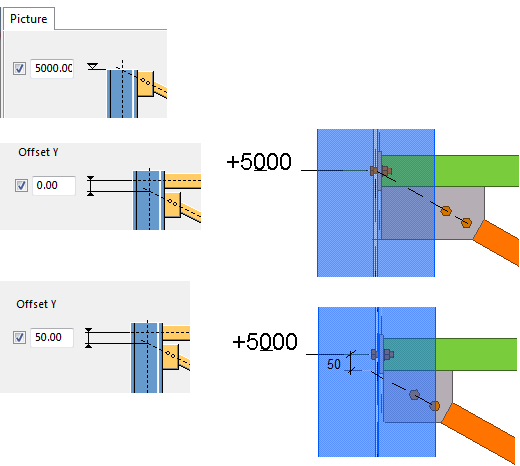
| Y offsets
X offsets |
Define the horizontal and vertical offset of
the bracing. Reference is the level defined on the Picture tab. For example:
|
|
Position in plane Rotation Position in depth |
Select the orientation of the compression bars. |
|
Option |
Description |
Default |
|---|---|---|
|
Pos_No |
Prefix and start number for the part position number. Some components have a second row of fields where you can enter the assembly position number. |
The default part start number is defined in the Components settings in . |
|
Material |
Material grade. |
The default material is defined in the Part material box in the Components settings in . |
|
Name |
Name that is shown in drawings and reports. |
|
|
Class |
Part class number. |
|
|
Finish |
Describes how the part surface has been treated. |
Joints tab
Use the Joints tab to define the components used for connecting the main parts and the diagonal bracing elements and the compression bars.
| Option | Description |
|---|---|
| Creation of joints |
Select whether connections are created between the bracing elements. No: Only the bracing elements are created. Yes: Components are added between the bracing elements. |
|
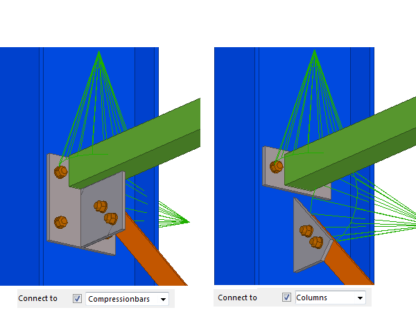
Connect to |
Select whether the bracing elements are connected to the main parts or the compression bars. For example:
|
|
Connection number Connect diagonals with joint number Userjoint application number Joint direction |
Type the component number that is used for
connecting the bracing, the diagonal bracing cross, or the
compression bar, and the component application number. Select
the connection direction for the diagonal bracing cross.
|
|
Configuration file for the joint |
Configuration setting for the connection. For example, if you type CS_M13, it means that a setting named CS_M13 must be available for the used connection. |
|
Tensioner position |
Define the tensioner position if the Tensioner (7) connection is used. |
Joints dir tab
Use the Joints dir tab to control the up directions of the connections used between the main parts and the diagonal bracing, and the up direction of the connections used between the main parts and the compression bars.
In the example below, Seating (30) has been defined as the connecting component on the Joints tab:

UDA tab
Use the UDA tab to add information in the user-defined attributes (UDAs) of the parts.
| Option | Description |
|---|---|
| Part | Select to which part the related information can be saved. |
| UDA name | Enter the name of the user-defined attribute. |
| Type | Select the UDA type. Use String for text, Integer for numbers, Float for numbers with decimals and Option for selecting an item in a list. |
| Value | Enter the value that is saved to the user-defined attribute. Use text and/or numbers, depending on the defined UDA type. |