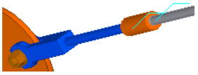
Tensioner central gusset (18)
Tensioner central gusset (18) creates a gusset plate to connect bracing bars.
Objects created
-
Gusset plate
-
Fork or plate
-
Tensioners (optional)
-
Bolts
-
Welds
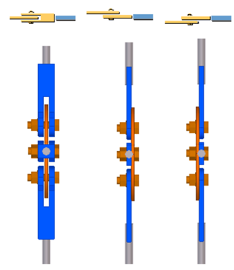
Use for
| Situation | Description |
|---|---|
|
|
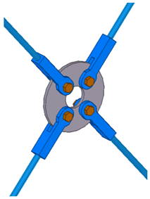
Round gusset plate with a hole. |
|
|
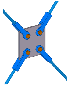
Square gusset plate. |
|
|
Round gusset plate. Tensioners are created. |

Before you start
Model at least 3 bracing bars.
Selection order
-
Select the bracing bars.
-
Click the middle mouse button to create the central gusset plate and the forks.
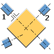
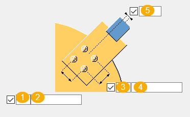
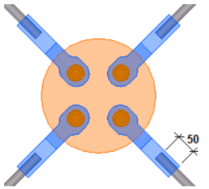
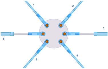
Part identification key
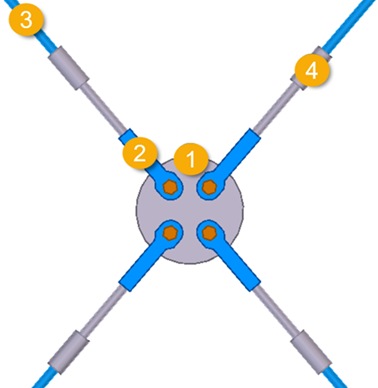
| Description | |
|---|---|
|
1 |
Gusset plate |
|
2 |
Fork |
|
3 |
Bracing bar |
|
4 |
Tensioner |
Picture tab
Use the Picture tab to define the shape and the dimensions of the central plate.
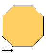
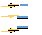
Gusset plate shape
| Option | Description |
|---|---|
|
|
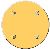
Circular gusset plate |
|
|
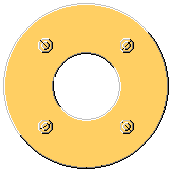
Circular gusset plate with a hole |
|
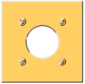
|
Square gusset plate with a hole |
|
|
Square gusset plate |

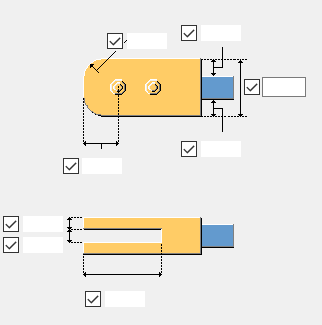
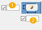
Gusset plate dimensions
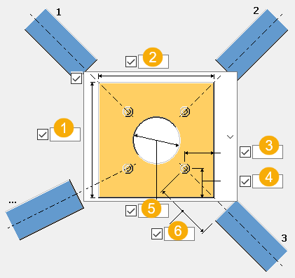
| Description | |
|---|---|
|
1 |
Height of the gusset plate. |
|
2 |
Width of the square gusset plate. |
|
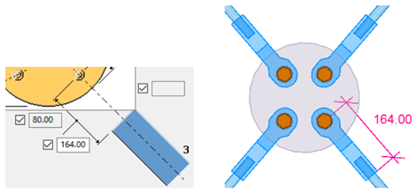
3 |
Bolt edge distance. Horizontal bolt edge distance for square gusset plates. |
|
4 |
Vertical bolt edge distance for square gusset plates. |
|
5 |
Diameter of the hole in the gusset plate. |
|
6 |
Fork length, calculated from the center of the hole to the end of the fork.
|
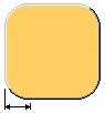
Chamfer shape and dimension
| Option | Description |
|---|---|
|
|
No chamfers |
|
|
Line chamfer Define the chamfer dimension. |
|
|
Convex chamfer Define the chamfer dimension. |

Gusset plate position
Select the position of the gusset plate relative to the bracing bars.
| Option | Descriptioin |
|---|---|
|
|
Middle of the corner between the first and the second bar. |
|
|
Perpendicular to the first bar. |

Create plate as
-
Contour plate. The profile can be PL12, for example.
-
Beam. The profile can be PL300*300, for example.
Enter the prefix of the beam profile. You can only enter the prefix if the plate is created as a beam profile.
Fork tab
Use the Fork tab to define the fork properties.
Parts
| Option | Description |
|---|---|
|
Plate |
Thickness of the fork. |
|
Option |
Description |
Default |
|---|---|---|
|
Pos_No |
Prefix and start number for the part position number. Some components have a second row of fields where you can enter the assembly position number. |
The default part start number is defined in the Components settings in . |
|
Material |
Material grade. |
The default material is defined in the Part material box in the Components settings in . |
|
Name |
Name that is shown in drawings and reports. |
|
|
Class |
Part class number. |
|
|
Finish |
Describes how the part surface has been treated. |
Part shape and dimensions
Select the shape of the fork: Part 1 or Part 2.
| Options | Description |
|---|---|
|
|
Define the dimensions of the reduced fork. |
|
|
Define the dimensions of the fork. |

Parameters tab
Use the Parameters tab to define the end plate properties, shape, and dimensions.
Parts
| Option | Description |
|---|---|
|
End plate |
Thickness, width, and height of the end plate. |
|
Option |
Description |
Default |
|---|---|---|
|
Pos_No |
Prefix and start number for the part position number. Some components have a second row of fields where you can enter the assembly position number. |
The default part start number is defined in the Components settings in . |
|
Material |
Material grade. |
The default material is defined in the Part material box in the Components settings in . |
|
Name |
Name that is shown in drawings and reports. |
|
|
Class |
Part class number. |
|
|
Finish |
Describes how the part surface has been treated. |
End plate shape
| Option | Description |
|---|---|
|
|
Default Square AutoDefaults can change this option. |
|
|
Square |
|
|
Round |


End plate offset
| Option | Description | Example |
|---|---|---|
|
|
Define the end plate offset from the bracing bar. |
End plate thickness is set to 30 and the offset it set to 5.
|


Bolts tab
Use the Bolts tab to define the bolt group dimensions and bolt properties.
Bolt group dimensions
| Description | |
|---|---|
|
1 |
Number of bolts in the longitudinal direction (axial to the bar). |
|
2 |
Bolt spacing in the longitudinal direction. |
|
3 |
Number of bolts in the transverse direction. |
|
4 |
Bolt spacing in the transverse direction. |
|
5 |
Bolt group offset in the transverse direction. |
Bolt basic properties
| Option | Description | Default |
|---|---|---|
|
Bolt size |
Bolt diameter. |
20 mm |
|
Bolt standard |
Bolt standard to be used inside the component. |
4014-8.8 |
|
Tolerance |
Gap between the bolt and the hole. |
3 mm |
|
Thread in mat |
Defines whether the thread may be within the bolted parts when bolts are used with a shaft. This has no effect when full-threaded bolts are used. |
|
|
Assembly type |
Location where the bolts should be attached. |
Site |
Slotted holes
You can define the dimensions of the slotted holes in the horizontal and vertical direction, and a gap for oversized R tapped holes. The default is 0 mm, which creates a circular hole.
| Description | |
|---|---|
|
1 |
Vertical dimension of the slotted hole. |
|
2 |
Horizontal dimension of the slotted hole. |
Bolt assembly
The selected check boxes define which component objects (bolt, washers, and nuts) are used in the bolt assembly.
If you want to create a hole only, clear all the check boxes.

To modify the bolt assembly in an existing component, select the Effect in modify check box and click Modify.
Bolt length increase
Define how much the bolt length is increased. Use this option when, for example, painting requires the bolt length to be increased.

Tensioner T tab
Use the Tensioner T tab to define the properties and dimensions of the tensioners.
Parts
| Option | Description | Default |
|---|---|---|
|
Tensioner T |
Select the profile from the profile catalog. |
D40 |
|
Part B |
Select the profile from the profile catalog. This is the bar profile between the fork and the tensioner. |
|
Option |
Description |
Default |
|---|---|---|
|
Pos_No |
Prefix and start number for the part position number. Some components have a second row of fields where you can enter the assembly position number. |
The default part start number is defined in the Components settings in . |
|
Material |
Material grade. |
The default material is defined in the Part material box in the Components settings in . |
|
Name |
Name that is shown in drawings and reports. |
|
|
Class |
Part class number. |
|
|
Finish |
Describes how the part surface has been treated. |
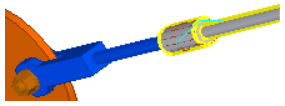
Create tensioner
| Opion | Description | Example |
|---|---|---|
|
|
Tensioner is not created. |
|
|
|
Tensioner is created. |
|
|
|
Tensioner is created. The stopper part is added to the bracing. Used for compression tubes. |
|
|
|
Tensioner is created. The stopper part is placed inside the compression tube. |
|
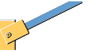
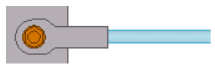
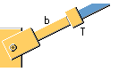


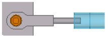
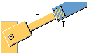
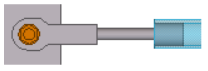
Plate position
| Option | Descriptino | Example |
|---|---|---|
|
|
Define the position of the plate on the fork. |
|

Fork position
| Option | Description | Example |
|---|---|---|
|
|
Define the position of the fork on the bracing bar. |
|

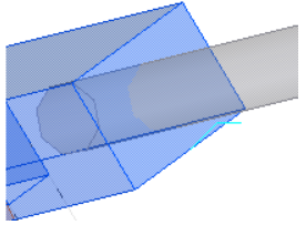
Opening in fork
| Option | Description | Example |
|---|---|---|
|
|
Select whether an opening is created in the fork. The opening is always square. You can define the opening if both the tensioner and an extra bracing bar are created. |
|
|
|
Define the gap for the opening. |
The default value is 1 mm.
|


Dimensions

| Description | Default | |
|---|---|---|
|
1 |
Define an overlap for the extra bracing bar in the tensioner. |
0 mm |
|
2 |
Define an overlap for the bracing bar.
|
|
|
3 |
Define the length of the extra bracing bar between the fork and the tensioner. |
300 mm |
|
4 |
Define the length of the tensioner. |
40 mm |
|
5 |
Define an overlap for the bracing bar in the tensioner. |
0 mm |
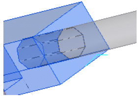
Cut part B in fork
Select whether the fork is cut if the bracing bar goes through the fork. The fork cut adapts to the size of the bracing bar.
| Example | Description |
|---|---|
|
|
Part B is cut. |
|
|
Part B is not cut. |
Tensioner T add to secondary
Select whether the tensioner is added to the bracing bar, or handled as a loose part and welded to the bracing bar.
|
|
Select Yes to add the tensioner to the bracing bar. |
|
|
Select No to weld the tensioner to the bracing bar. |
Extra tensioners
Use the Extra tensioners tab to define the properties and dimensions of extra tensioners. You can define two types of tensioners. You can define extra tensioners if more than one bracing bar is connected. If there is only one bracing bar, the settings on the Tensioner T tab are used for tensioners.
Parts
| Option | Description |
|---|---|
|
Tensioner T |
Select the profile from the profile catalog. |
|
Part B |
Select the profile from the profile catalog. This is the bar profile between the fork and the tensioner. |
| Option | Description |
|---|---|
|
Apply on tensioner number |
Define the bars on which the setting for the extra tensioners is applied. Use a space to define several bar numbers.
|
|
Option |
Description |
Default |
|---|---|---|
|
Pos_No |
Prefix and start number for the part position number. Some components have a second row of fields where you can enter the assembly position number. |
The default part start number is defined in the Components settings in . |
|
Material |
Material grade. |
The default material is defined in the Part material box in the Components settings in . |
|
Name |
Name that is shown in drawings and reports. |
|
|
Class |
Part class number. |
|
|
Finish |
Describes how the part surface has been treated. |
Create tensioner
| Option | Description |
|---|---|
|
|
Tensioner is not created. |
|
|
Tensioner is created. |
|
|
Tensioner is created. The stopper part is added to the bracing. Used for compression tubes. |
|
|
Tensioner is created. The stopper part is placed inside the compression tube. |
Dimensions
| Description | |
|---|---|
|
1 |
Define an overlap for the extra bracing bar in the tensioner. |
|
2 |
Define an overlap for the bracing bar. |
|
3 |
Define the length of the extra bracing bar between the fork and the tensioner. |
|
4 |
Define the length of the tensioner. |
|
5 |
Define an overlap for the bracing bar in the tensioner. |
Cut part B in fork
Select whether the fork is cut if the bracing bar goes through the fork (Yes). The fork cut adapts to the size of the bracing bar.
Tensioner T add to secondary
Select whether the tensioner is added to the bracing bar (Yes), or handled as a loose part and welded to the bracing bar.
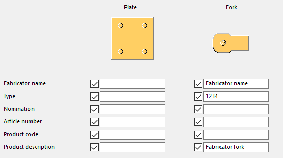
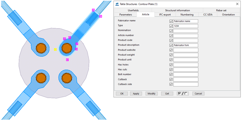
UDA tab
Use the UDA tab to define user-defined attributes (UDA). The attributes are written to the central gusset and forks.
Example
Define the needed user-defined attributes.
General tab
Click the link below to find out more:
Analysis tab
Click the link below to find out more:
Welds
Click the link below to find out more: