Welded beam to beam (123)
Welded beam to beam (123) connects two beams using a fully welded connection. The beams can have welding preparations. Stiffener plates with welding preparations can also be created.
Limitations
-
You can only use I-section beams.
-
You cannot use beams that are horizontally skewed or vertically sloped.
Objects created
-
Stiffeners
-
Cuts
-
Welds
Use for
| Situation | Description |
|---|---|
|
|
Fully welded beam to beam connection |

Selection order
-
Select the main part (beam).
-
Select the secondary part (beam).
The connection is created automatically when the secondary part is selected.
Part identification key
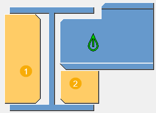
| Description | |
|---|---|
|
1 |
Front stiffener |
|
2 |
Back stiffener |
Picture tab
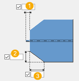
Use the Picture tab to define the beam and stiffener offset dimensions.
Dimensions
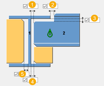
| Description | |
|---|---|
|
1 |
Gap dimension between the main part web and the secondary part edge. |
|
2 |
Secondary part offset dimension from the main part flange. |
|
3 |
Secondary part offset dimension from the underside of the main part flange. |
|
4 |
Back stiffener offset dimension from the main part web. |
|
5 |
Front stiffener offset dimension from the main part web. |
Parameters tab
Use the Parameters tab to define the stiffener plate properties, and whether weld preparations are required.
Plates
| Option | Description |
|---|---|
|
Btm stiff plate |
Thickness and width of the stiffener on the main beam side. |
|
Back stiffener |
Thickness and width of the stiffener located behind the secondary beam. |
|
Option |
Description |
Default |
|---|---|---|
|
Pos_No |
Prefix and start number for the part position number. Some components have a second row of fields where you can enter the assembly position number. |
The default part start number is defined in the Components settings in . |
|
Material |
Material grade. |
The default material is defined in the Part material box in the Components settings in . |
|
Name |
Name that is shown in drawings and reports. |
Weld preparation creation, beam web and flange thickness
| Option | Description | Default |
|---|---|---|
|
Are weld preparations required |
Select whether to create weld preparations. |
Weld preparations are not created. |
|
Root face thickness of web at U/S of flange |
Set the minimum thickness of the main beam web after the weld preparation cut. The minimum value is 2.0 mm. If you do not enter a value, the minimum value is used. Note that if you have defined a double-sided weld preparation, the root face thickness is centred on the web of the beam. |
|
|
Root face thickness of web |
Set the minimum thickness of the incoming beam web after the weld preparation cut. The minimum value is 2.0 mm. Note that if you have defined a double-sided weld preparation, the root face thickness is centred on the web of the beam. |
|
|
Root face thickness for front stiffener |
Set the minimum thickness of the front stiffener after the weld preparation cut. The minimum value is 2.0 mm. Note that if you have defined a double-sided weld preparation, the root face thickness is centred on the stiffener. |
The default value is the thickness of the flange, that is, no weld preparation other than a gap can be created unless you define a root face thickness. |
|
Root face thickness for rear stiffener |
Set the minimum thickness of the back stiffener after the weld preparation cut. The minimum value is 2.0 mm. Note that if you have defined a double-sided weld preparation, the root face thickness is centred on the stiffener. |
The default value is the thickness of the flange, that is, no weld preparation other than a gap can be created unless you define a root face thickness. |
|
Use flange slope ratio |
Select whether the flange slope ratio is used in notch cuts. |
Define weld preparations
You can apply various weld preparations to the main beam flanges and web, and to the stiffener plates.
By default, the connection automatically detects whether the top and bottom flanges of the main beam clash with the flanges of the secondary beam. This determines how the weld preparations are handled.
If the main beam does not have the same section size as the secondary beam, the connection detects which flange is free based on which of the top or the bottom flanges are still clashing.
The following explains the basic weld preparation situations of each section of the main beam:
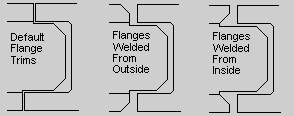
| Situation | Description |
|---|---|
|
Default |
The top flange
is cut back to avoid the top flange of the secondary beam.
You can define the secondary part offset from the main part
flange in Set Are weld preparations required on the Parameters tab to Yes. |
|
Weld from the outside |
To create a weld preparation that shapes the top flange so that it can be welded from the outside, first set Are weld preparations required on the Parameters tab to Yes. Click the Welds button to define the weld settings:
|
|
Weld from the inside |
To create a weld preparation that shapes the top flange so that it can be welded from the inside, first set Are weld preparations required on the Parameters tab to Yes. Click the Welds button to define the weld settings:
|
 and
and
 on
the
on
the  .
You can also define the size and angle of the
weld.
.
You can also define the size and angle of the
weld.Main beam web
Note that if you define any weld preparation on the beam web, the weld preparation is created on the vertical face of the web and the horizontal face of the web at the underside of the secondary beam flange.
| Situation | Description |
|---|---|
|
Default situation |
The default weld preparation of the main beam web is to fit the beam to the side of the secondary beam web. Set Are weld preparations required on the Parameters tab to Yes. If needed, define that a gap is created between the two webs
in |
|
Weld from the near side |
Set Are weld preparations required on the Parameters tab to Yes. Click the
Welds button to define the weld
settings. For weld number 2, change the top half of
Type from fillet weld to penetration
weld Check on the Parameters tab that the root face thickness values are as needed. |
|
Weld from the far side |
Set Are weld preparations required on the Parameters tab to Yes. Click the
Welds button to define the weld
settings. For weld number 2, change the bottom half
of Type from fillet weld to
penetration weld Check on the Parameters tab that the root face thickness values are as needed. |
|
Weld from both sides |
Set Are weld preparations required on the Parameters tab to Yes. Click the
Welds button to define the weld
settings. For weld number 2, change both the top and
the bottom halves of Type from fillet
weld to penetration weld Check on the Parameters tab that the root face thickness values are as needed. |
 on the
 Front and back stiffener plates
If you define any weld preparation on the front and back stiffener, it is created on the three stiffener sides that are welded to the main beam and the secondary beam.
| Situation | Description |
|---|---|
|
Default situation |
For the default situation, see the description of the main beam web. The welds you need to define are weld number 5 for the front stiffener and weld number 6 for the back stiffener. |
|
Weld from the near side |
See the description of the main beam web. The welds you need to define are weld number 5 for the front stiffener and weld number 6 for the back stiffener. |
|
Weld from the far side |
See description of the main beam web. The welds you need to define are weld number 5 for the front stiffener and weld number 6 for the back stiffener. |
|
Weld from both sides |
See the description of the main beam web. The welds you need to define are weld number 5 for the front stiffener and weld number 6 for the back stiffener. |
Chamfers tab
Use the Chamfers tab to define the weld access hole dimensions.
Secondary beam weld access hole dimensions
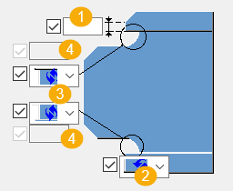
| Description | |
|---|---|
|
1 |
Vertical flange dimension. |
|
2 |
Flange cut shape. |
|
3 |
Weld access hole shape. |
|
4 |
Radius of the weld access hole. |
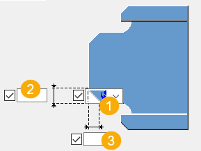
Beam end dimensions
| Description | |
|---|---|
|
1 |
Length of the secondary beam web. This is the flange cut distance from the start of the web. |
|
2 |
Vertical chamfer dimension. |
|
3 |
Horizontal chamfer dimension. |
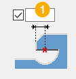
Weld access hole offset
| Description | |
|---|---|
|
1 |
Weld access hole offset along the secondary beam axis. |
Secondary beam web chamfers
| Description | |
|---|---|
|
1 |
Chamfer shape |
|
2 |
Vertical chamfer dimension |
|
3 |
Horizontal chamfer dimension |
General tab
Click the link below to find out more:
Design tab
Click the link below to find out more:
Analysis tab
Click the link below to find out more:
Welds
Click the link below to find out more: