Tekla Structures 2020 India environment Release Notes
2020
Tekla Structures
Environment
India
1. Steel Settings:
1.1 Drawing Layout Updates
All drawing attributes modified which are available in "Steel" and "Engineering" role as per new drawing layout changes.
All drawing layout files modified as per new drawing layout changes.
Steel role:
Image

Engineering role:
Image

1.2 Steel Components:
1.2.1 System components:
The below information helps you to know about the fixes & new option(s) which are available in the components.
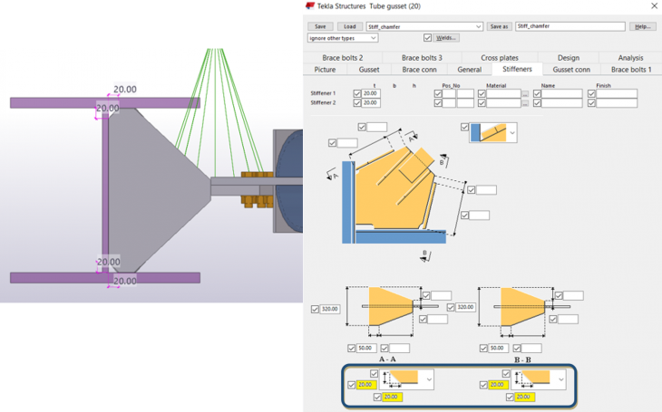
1) It is now possible to create chamfers on the stiffeners on tab page Stiffeners.
Connection(s): (20) Tube gusset
Attribute(s): Stiff_chamfer.j20
Image
2) It is now possible to cut secondary part in the specified distance from the primary part center.
Connection(s): (23) Round tub
Attribute(s): Cut_Specified distance.j23
Image

3) It is now possible to use weld #7 as weld between plates and secondary part.
Connection(s): Welded and stiffened shear plate (43)
Attribute(s): No attribute created
Previously, we have weld option in 3 sided only, now we can provide the weld in 4th side also. (# Weld 7)
Image

4) It is now possible to create plate washers using options on tab page Parts.
Connection(s): H&V Shear Pl (64)
Attribute(s): Plate_washer.j310000064
Image

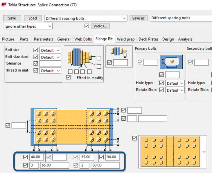
5) It is now possible to specify different number of bolts and different spacing between bolts for primary and secondary web and flange bolts.
Connection(s): Splice Connection (77)
Attribute(s): Different spacing bolts.j77
Image
6) It is now possible to specify part name of the tab plate
Connection(s): Extend full depth tab (82)
Attribute(s):No attribute created
Image

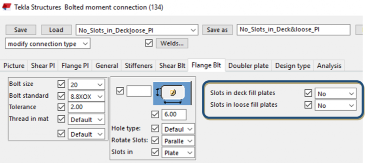
7) It is now possible to specify whether slotted holes required in deck fill plates and loose fill plates or not
Connection(s): Bolted moment connection (134)
Attribute(s): No_Slots_in_Deck&loose_Pl.j134
Image
8) It is now possible to create haunch as plates.
Connection(s): Offshore (194)
Attribute(s): plates.j194
Image

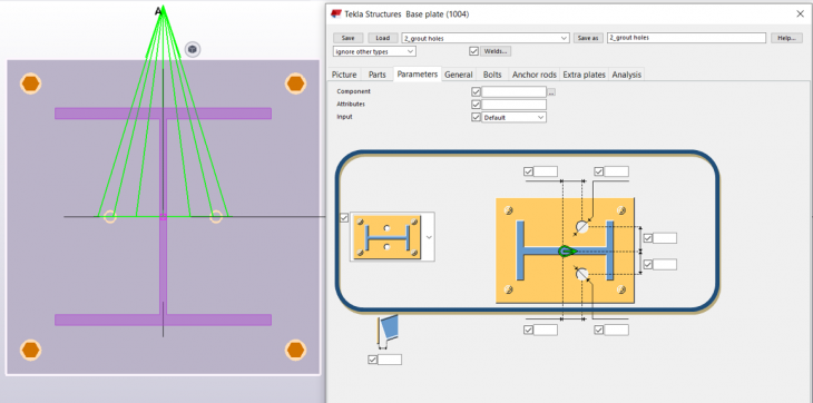
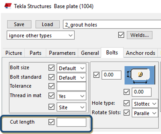
9) It is now possible to specify bolt cut length on “Bolts” tab and it is now possible to specify creation of two grout holes in base plate on “Parameters” tab.
Connection(s): Base plate (1004)
Attribute(s): 2_grout holes.j1004
Image
Image
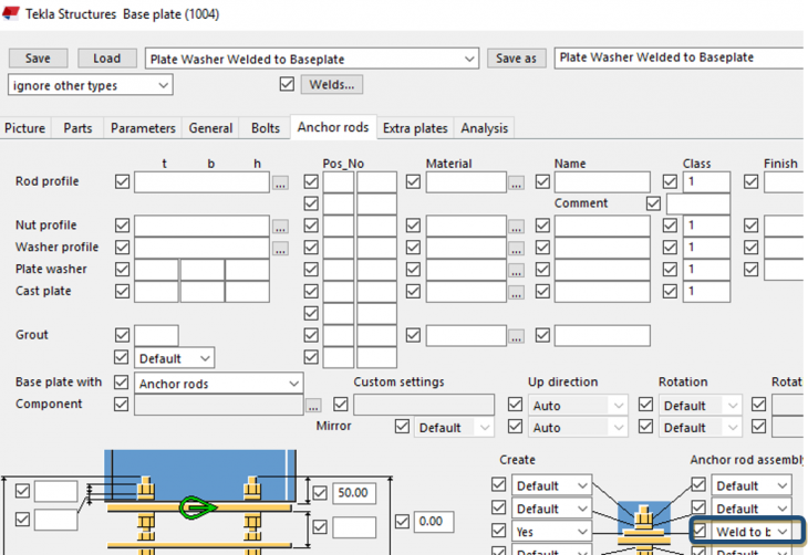
10) It is now possible to weld plate washers to the base plate using option on tab page Anchor rods.
Connection(s):
Base plate (1004), Stiffened base plate (1014), Web stiffened base plate (1016), Base plate (1042), U.S. Base plate (1047),
Circular base plate (1052) and Tapered column base plate (1068):
Attribute(s):
Plate Washer Welded to Baseplate.j1004
Plate Washer Welded to Baseplate.j1014
Plate Washer Welded to Baseplate.j1047
Plate Washer Welded to Baseplate.j1016
Plate Washer Welded to Baseplate.j1042
Plate Washer Welded to Baseplate.j1052
Plate Washer Welded to Baseplate.j1068
Previously, we have the option to weld the plate washers along with the anchor rods (as assembly) or option to send the plate washers as loose part.
Image
11) It is now possible to specify bolt cut length on “Bolts “tab.
Connection(s): Stiffened base plate (1014), Base plate (1042), U.S. Base plate (1047)
Attribute(s): No attribute created
Image

12) It is now possible to specify material of extra profiles on tab page Extra plates
Connection(s): Stiffened base plate (1014), Base plate (1042), U.S. Base plate (1047)
Attribute(s): No attribute created
Image

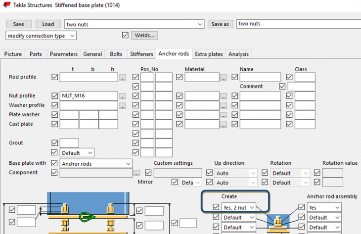
13) It is now possible to create two nuts at the top of the anchor rods using option on tab page Anchor rods.
Connection(s):
Stiffened base plate (1014), Base plate (1042), U.S. Base plate (1047)
Attribute(s):
two nuts .j1014
two nuts.j1047
two nuts .j1042
Image
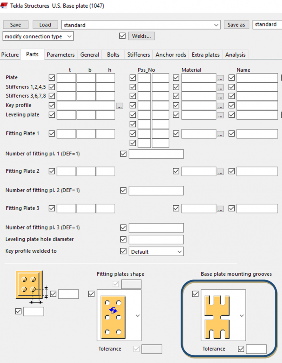
14) It is now possible to create mounting grooves in the base plate using options on tab page Parts.
Connection(s): Stiffened base plate (1014), Base plate (1042), U.S. Base plate (1047)
Attribute(s): No attribute created
Image
15) Stiffeners default width is now calculated using advanced option XS_STANDARD_STIFFENER_WIDTH_TOLERANCE
Connection(s):
Stiffened base plate (1014), Web stiffened base plate (1016), Stiffened shear plate (17), Beam with stiffeners (129), Column with shear plate (131),
Bolted moment connection (134), Beam to beam stub (135), Clip angle (141), Bent plate (151), Moment connection (181),
Column with stiffeners W (182), Column with stiffeners (186), Column with stiffeners S (187)
Attribute(s): No attribute created
Image

16) It is now possible to create plate washers below base plate.
Connection(s): U.S. Base plate (1047)
Attribute(s): Plate washers below base plate.j1047
Image

Image

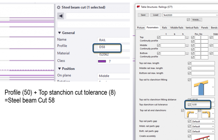
17) Options Top rail to stanchion fitting - Stanchion part cut and other rail to stanchion fitting - Rail part cut now have extended functionality.
User can specify also fitting distance so parts which will be cut are fitted at first to the middle of the cutting part and then cut.
Connection(s): Railings (S77)
Attribute(s): No attribute created
Image
Image

2. Concrete Settings
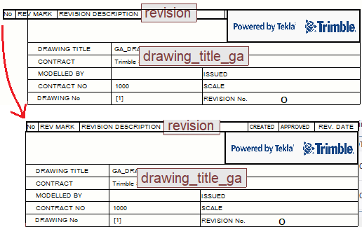
2.1 Drawing Layout Updates
Frame margins is set to zero in order to make drawing sizes created in Layout editor equal to paper sizes in the printing tool.
Image

Updated Layout files:
Image

Updated Drawing settings:
Image

Overlapping Tables are repositioned:
Image
2.2 Rebarset
2.2.1 Part local coordinate system based concrete covers
Below Layer Prefix and cover are set as default values in standard.opt file
Image

Co-ordinate system for concrete cover is added to Property Pane through Property Template:
“PropertyTemplates.xml” It enables selection of concrete cover coordinate.
Image

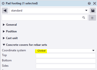
Default Settings: Attribute file “standard”
Co-ordinate system for cover is set to Global for Pad Footing to get proper layer prefix.
Image
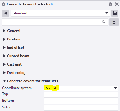
Default Settings: Attribute file “standard”
Co-ordinate system for cover is set to Global for Beam to get proper layer prefix.
Image
Default Settings: Attribute file “standard”
Co-ordinate system for cover is set to Global for Strip Footing to get proper layer prefix.
Image
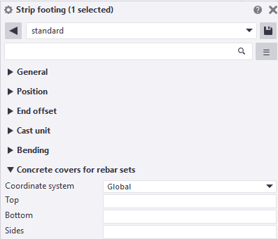
Default Settings: Attribute file “standard”
Co-ordinate system for cover is not set to Columns, because the side bars and corner bars are named separately for columns.
Image
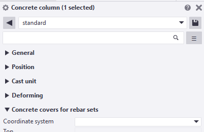
Default Settings: Attribute file “standard”
Co-ordinate system for cover is set to Local for Wallpanel to get proper layer prefix.
Image
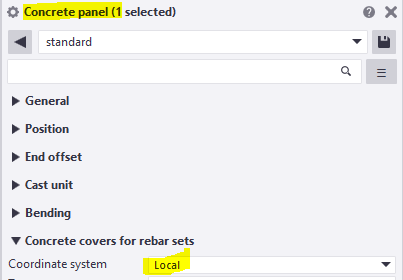
Default Settings: Attribute file “standard”
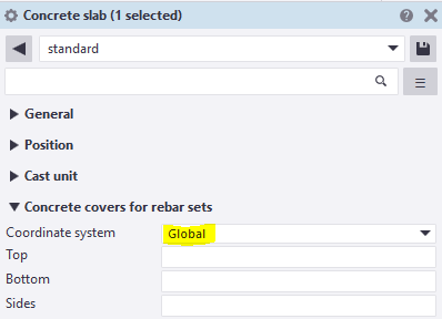
Co-ordinate system for cover is set to Local for Slab to get proper layer prefix.
Image
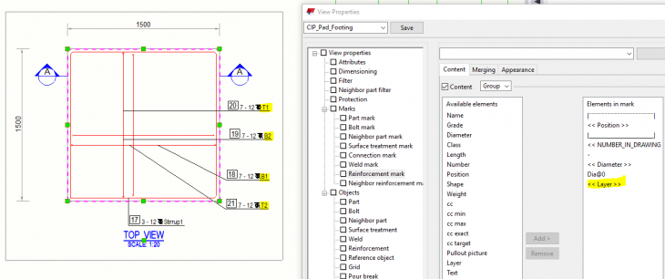
2.2.2 Bar LAYER as a reportable property
Drawing settings are made to reflect Layer number in the Rebar Mark:
Pad Footing:
Image
Wall Panel:
Image

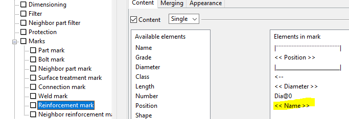
For Column, Strip footing and Beam the Stirrup is considered as first layer and First Top and Bot bar gets layer number as 2. So, resulting in T2, T3 and B2, B3 instead of T1, T2 and B1, B2. So Layer is not called in these two drawing settings. Instead of Layer, Name is called.
Image
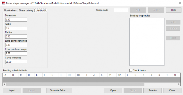
2.3 Rebar Shape Manager
2.3.1 Tolerance is set as 20mm is retained in 2020 version.
Image
2.3.2 Advance settings is retained as TRUE to consider the combine option:
Image

2.3.3 New Shape added for Bar with straight and curved portion. 67A
Modelled with multiple pick points:
Image
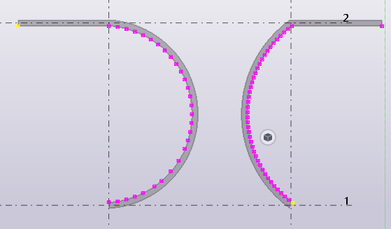
Starting with Straight leg and starting with curved leg side. Both options are considered.
Image
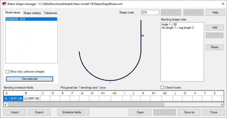
Additional Rule condition given : Arc length is greater than straight leg length
Image

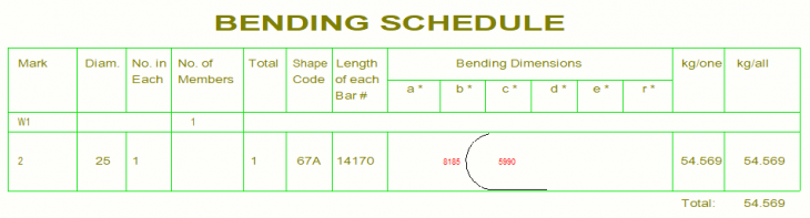
2.3.4 BBS template is updated so that it will not display all the dimensions for each leg.
Image
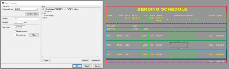
Image
2.4 Rebar Dimension Mark
2.4.1 rebar_dimension_mark.dim added with below settings.
Dimension to: Start and End bar
Subgrouping: No
Extension line to visible rebar: Yes
Combine equal dimensions to 3*60=180
Minimum to combine: 1
Set the value contents prefix (Dimension mark contents prefix).
Set the value visibility of value (Dimension mark contents value visibility) to Hidden.
Image

2.4.2 rebar_tagged_dimension_mark.dim added with below settings
Dimension to: All rebars
Subgrouping: No
Extension line to visible rebar: Yes
Combine equal dimensions to 3*60=180
Minimum to combine: 1
Appropriate tag contents.
Image

2.5 Custom components and Form work tool
2.5.1 Below Pile and Pilecap custom components from India Environment are moved to Tekla Warehouse (Link)
CIP_Pile_2
CIP_Pile_3
CIP_Pile_5
CIP_Pile_6
CIP_Pile_9
Image
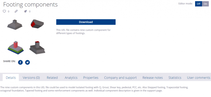
2.5.2 Below Footing custom components from India Environment are moved to Tekla Warehouse (Link)
Iso footing
Footing_Iso
Octagonal foundation
Sleeper_TIN
Step_ftg_1
Step_ftg_2
Stepped isolated footing
Tapered footing
Turned down slab
Image
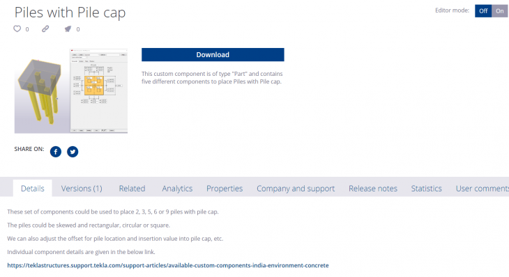
Please check this article for the list of Custom Components available in India Environment.
2.5.3 Formwork placing tools
Formwork Ribbon and system components are now available in Contractor role and Rebar Detailer Role.
Image

2.6 New content type HIERARCHIC_CAST_UNIT
New content type HIERARCHIC_CAST_UNIT for reporting is included in Cast unit Inquire report.
Image

2.7 Mesh Representation
Attribute file: Mesh-representation.vr - New feature, "Single line with filled end" for Mesh representation is incorporated in this settings.
Image

2.8 Concrete Components
2.8.1 Corbel Reinforcement (81):
- New combo box added which allow reinforce column with traverse stirrups.
- Fixed reinforcing corbels which are thicker than column.
Standard attribute file updated: standard.m30000081. Works for single and double corbel.
Image
Image

2.8.2 Hollow core lifting loops: Option for 2 or 4 lifters
Default standard file settings with 4 lifters is retained.
Image

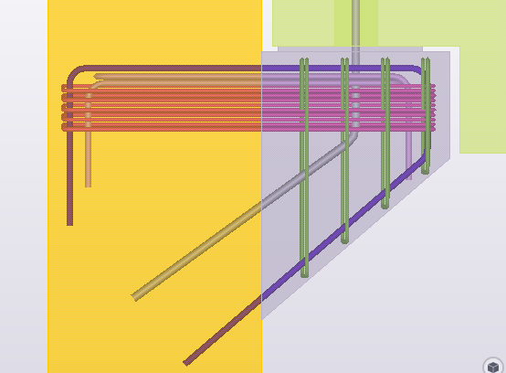
2.8.3 Rebar Group Dimensioning
Dimension_mark attribute selected and Left side and Right side content defined.
Attribute files:
Ind.RebarGroupDimensionPlugin.RebarGroupDimensionPluginForm.xml
Leftside.RebarGroupDimensionPlugin.RebarGroupDimensionPluginForm.xml
Rightside.RebarGroupDimensionPlugin.RebarGroupDimensionPluginForm.xml
Image

Image

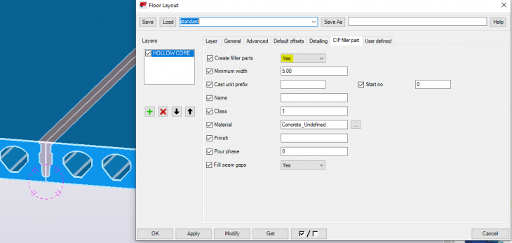
2.8.4 Floor Layout
Filler added to the standard attribute file: standard.Layout.UI.Dialogs.SlabLayersForm.xml
Image
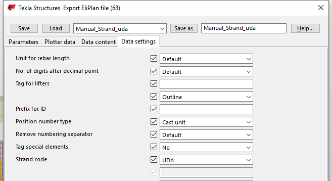
2.8.5 EliPLAN Export
System component, "Hollow core reinforcement strands" is usually used to write the strand code.
For users who do not use that particular system component store the strand code with other UDA. So, for manual strand, new attribute file is created with the selection of UDA in strand code: Manual_Strand_uda.m170000068
Image
2.8.6 Unitechnik-export
Attribute file: Simplified-contour.m160000079 added for new export CONTOUR option for simplifying external contour.
Image
