Release Info Tekla Structures 2023
2023
Tekla Structures
Environment
Construsoft European
The Release Info Tekla Structures 2023 includes the following topics:
General
Construsoft Online panel in side pane extended
The side pane in Tekla Structures includes the Construsoft Online panel (1):
Image

When you start Tekla Structures 2023 for the first time, you need to log in into the Online panel. You will see a red Construsoft logo in the upper right corner of your screen.
When you log in now, this login is saved on your computer and in the future, when a new Tekla Structures version is available, you will not have to log in again.
In addition, the Pack & Go tool (m161) has been added (2) to the Construsoft Online panel. You use the tool to save the model data and other necessary files and information in one zip file, for example to archive models or to send them to the Construsoft Helpdesk.
Display & filtering in the side pane: existing option improved and new option added
Tekla Structures includes the side pane in the Model Editor on the right side where you can run various commands such as the command Display & filtering (1). By default, this command includes four tabs (2):
Image

Assembly hierarchy: For displaying the hierarchy of assemblies, sub-assemblies, and super-assemblies.
Phases: For displaying different phases in model views.
Zone: For displaying different zones.
Attributes: For displaying different attributes.
Image
Click the Help button for more information.
Tab Phases
When you use this option to display the different phases in the model views, you can set whether you want to display them on part or assembly level or reinforcement:
Image

In earlier Tekla Structures versions, the Part option also displayed component symbols (and their contents such as welds and bolts) of the other phases. In Tekla Structures 2023, this has been improved so that only the relevant parts of the selected phase are now displayed.
Tab Zone
Since Tekla Structures 2022, the tab Zone has been expanded to include the Template option. To do this, go to the tab Zone tab and right-click, a pop-up menu appears:
Image

When you select the option Template, the following dialog box appears, and you can select a template attribute:
Image

and display these in model views, for example the applied profile types (I profiles or RHS profiles):
Image

Next, you can select profiles from these:
Image

and create a list, drawings, or NC files, for example.
Field Zone available in multiple objects
In the Timber Detailer role, you now also have the field Zone in the user defined attributes for bent and lofted plates where you can define the zone:
Image

NC files: Settings modified
In Tekla Structures 2023, for generating NC files, the All setting has been removed so that you only have the default settings Plates and Profiles:
Image

In addition, the NC file settings Plates and Profiles have been modified so that now the options that were entered for Maximum size of holes have been removed.
Tekla Structures 2022 Service Pack 6 and older:
Image

Tekla Structures 2023:
Image

The Maximum size of holes options define how large holes the machine tool can drill. The NC file is not created if a part contains larger holes or its material is thicker than the specified values. The hole size is connected to material thickness or plate thickness.
Each row contains the maximum hole diameter and the material thickness. Both conditions have to be met for the NC file to be created. For example, a row with the values 60 45 means that when the material thickness is 45 mm or smaller, and the hole diameter is 60 mm or smaller, the NC file is created. You can add as many rows as needed.
Personal settings
In case you have created settings for NC files in earlier Tekla Structures versions, you must save these settings once again.
If desired, copy the new settings from the folder attributes in the model folder to your Tekla Structures 2023 TS folder or save the settings in your model template so that they are available in all models.
NC files: Setting removed
When you created NC files in earlier Tekla Structures versions and then converted them to DXF files, you had to load the setting DSTV2DXF in the dialog box NC File Header Information for correct output in the DXF files:
Image

Image

By using the setting DSTV2DXF, the position of the Phase identification and Drawing identification was correct so that when converting the NC file to a DXF file, the correct information is included.
In Tekla Structures 2023, the setting DSTV2DXF is redundant (due to the new DSTV to DXF converter, see below) and therefore removed from the installation. You can now use the default setting in all cases.
TIP: Before converting NC files to DXF files, you can use the tool DSTV File Name Modifier to rename NC files.
New DSTV to DXF Converter
In earlier Tekla Structures versions, several tools for converting NC files to DXF files were available. These DXF files do not contain any unnecessary information such as dimension lines. Only the profile contours, the location of possible holes and user text is included in the converted DXF file.
In Tekla Structures 2023, a new DSTV to DXF converter is available:
Image
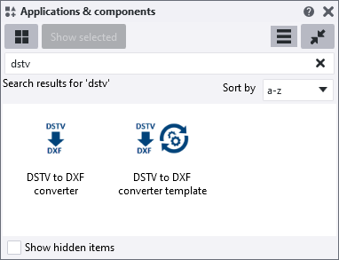
As a result, macro Convert DSTV to DXF (ML503) is no longer available in Tekla Structures 2023. You cannot migrate/make personal settings from this macro to the new DSTV to DXF Converter.
The new tool DSTV to DXF Converter includes the setting standard that you can use as a basis:
Image

This setting also eliminates the need for setting DSTV2DXF as described above.
In the Environment tab, the option Include blind holes is set to No by default so that these holes are not included when you convert NC files to DXF files:
Image

NOTE
In case you have plates with tapped holes, the outer diameter of the tapped holes (so, for example, 12 instead of 10.3 for a tapped hole M12) is included in the DXF file. This is not correct and you will have to adjust these DXF files manually.
As for using the new DSTV to DXF Converter, at least check the output to see if it meets your requirements, also based on using other/previous DSTV converters.
In addition, you now also have the tool DSTV to DXF converter-template. This is a converter template that you can use to automate the conversion process.
You can enter the required information in the template file in a text editor for this purpose. This eliminates the need to go through the settings in the DSTV to DXF Converter dialog box and allows you to perform the conversion by double-clicking a single button.
To enter the required information in a text editor, right-click the DSTV to DXF converter template button in the Applications and Components database, click Edit, and select an appropriate text editor.
Now scroll down to customize the desired strings.
Among other things, you can change the name of the setting to be used in the DSTV to DXF Converter or the default input and output folder:
Image

To use the custom settings, double-click on the DSTV to DXF converter-template tool.
Click here for detailed information about the new DSTV to DXF Converter and the DSTV to DXF converter-template tool.
New pdf report assembly _finish added
Tekla Structures 2023 now includes the new report PDF-assembly_finish.pdf in addition to the existing report assembly-finish-list:
Image

Localization: Update personal settings/files
General about localization
When you switch to Tekla Structures 2023 as a Tekla Structures user, you can use the settings and files that you modified in a previous Tekla Structures version. Tekla Structures will not copy them automatically, you must do it yourself.
There are some settings/files that we will highlight because these are possible customizations that you may have made in an earlier Tekla Structures version and cannot be copied to Tekla Structures without any further action.
Compare them to your situation and, if necessary, take the steps that apply to you. This allows you to start working in Tekla Structures 2023 quickly and easily.
It is recommended that you document your own changes by documenting them and using this Word document as a basis, possibly supplemented with your personal points of attention. In that way you always know what your adjustments are.
Update model templates
In case you have created model templates in earlier Tekla Structures versions, you must update the model templates to use them hassle-free in Tekla Structures 2023.
Click here for a general step plan.
Page numbering in reports
Tekla Structures 2023 includes the ability to use new page numbers in reports that also displays the total number of pages in the report.
Tekla Structures 2022 and earlier:
Image

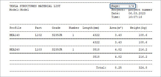
Tekla Structures 2023:
Image
For this, the new value field GetValue("PAGES") is available. In the Template Editor, the formula GetValue("PAGE")+"/"+GetValue("PAGES") is used:
Image

In case you have personal or custom reports, you can also customize these to display the total number of pages.
Construsoft has customized all available reports so that both page and total number of pages appear on the reports.
Saved settings for automatic view-level dimensions
General
In Tekla Structures, you can define settings for objects in drawing views. You should think about how parts are displayed or dimensioned in different views.
You can create multiple views of the same type, for example, multiple front views to clearly display the dimensions of, for example, embeds or reinforcement.
This gives you great flexibility: you can define where you want to dimension what, i.e. where the dimension lines are positioned, in what order they are created and what settings you want to use for each dimension line. The same applies for how to display parts.
The functionality applies to single-part, assembly, and precast concrete drawings, not to general arrangement drawings.
Click here for detailed information about automatic view-level dimensions.
In Tekla Structures 2023, the dimensioning method Filter has a new Only objects on the selected sides check box in rule creation allowing you to only dimension objects that are on a certain side of the main part, for example, Front side. By creating separate rules for each side you can have front and back side objects dimensioned on separate dimension lines:
Image

Image
Image

This improvement was already introduced in Tekla Structures 2022 SP2.
Personal settings
To ensure that your personal saved settings are appropriate for Tekla Structures 2023, do the following:
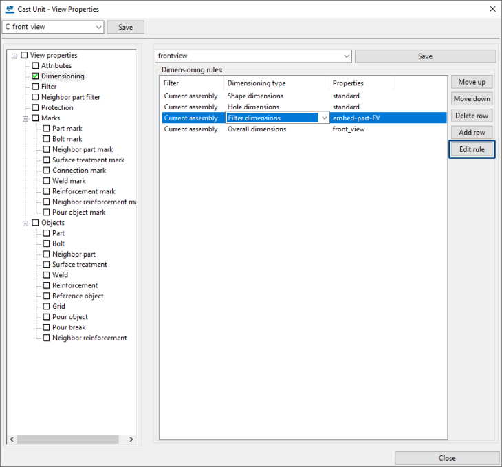
1. Copy the personal settings to Tekla Structures 2023, for example to the TS folder or to your model template.
The file extension is *.FilterDimXml, for example, embed-part-FV.FilterDimXml as shown in the image above.
2. Open Tekla Structures 2023 and select a personal setting from the drop-down list.
3. Set the desired option (1) and save the setting(s) again (2):
Image

4. Copy the setting(s) to your TS folder or to your model template (example model).
Filters in dimension lines
You have the option in Tekla Structures in the Drawing Editor in the dimension line properties to add tags when you open the properties dialog box of horizontal or vertical dimension lines, for example:
Image

General about dimension line tags
Dimension line tags are associated with the objects to which the dimension lines belong and can be used with all types of dimension lines. This additional information is automatically updated when changes are made to the model.
Excluded tags
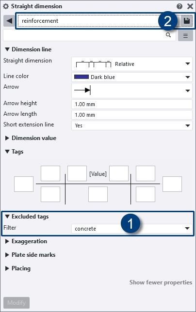
You can select a filter at the option Excluded tags that removes the desired default content from the tag.
Image

Click here for detailed information about dimension line tags and excluded tags.
NOTE
In general, if you use a setting whose filter does not exist, it will be indicated in the dialog box in the appropriate field:
Image

Action is required and you cannot use the Modify and Save buttons.
Personal settings
To ensure that your personal saved dimension line settings have appropriate filters, do the following:
1. Copy the personal dimension settings from an earlier Tekla Structures version to Tekla Structures 2023, for example to the TS folder or to your model template.
2. Open Tekla Structures 2023 and select a personal setting from the drop-down list.
3. Set the desired filter (1) and save the settings again (2):
Image
Select None from the drop-down list as tag filter if excluding is not required.
4. Copy the setting(s) to your TS folder or to your model template.
Advanced options for the clash check removed
In Tekla Structures 2023, the advanced options XS_CLASH_CHECK_BETWEEN_REFERENCES, XS_CLASH_CHECK_INSIDE_REFERENCE_MODELS and XS_CLASH_CHECK_BETWEEN_PARTS, which controlled clash check content, have been removed.
Indeed, you can set the way the clash check should perform since Tekla Structures 2022 Service Pack 2 in the Clash check manager dialog box using the Between Parts, Between reference models and Objects in reference models options:
Image

When you open Clash check manager for the first time after starting Tekla Structures, or after you have opened a new model, the Between parts setting is now by default set to selected, and the Between reference models and Objects in reference models settings are set to not selected.
If you have copied and modified any of these advanced options in an ini file, you can delete from the file.
About the Minimum distance
Set the Minimum distance (mm) between reference model objects, and between native Tekla Structures parts and reference model objects.
Objects that are closer to each other than the set minimum distance are reported in the clash check list. The highest possible minimum distance is 500 mm.
Click here for more information about using the Clash check manager and the options listed above.
Advanced option for hatching overlapping surfaces and dashed line for hidden line deleted
Since several Tekla Structures versions, you have the options Hatching of overlapping surfaces and Dashes line for hidden line (via File > Settings > Switches).
Image

The option Hatching of overlapping surfaces controls whether hatching is shown for overlapping surfaces in the DirectX rendering views.
The option Dashes line for hidden line controls whether the part hidden lines are visible in the DirectX rendered model views.
These options replace the previously used advanced options XS_HATCH_OVERLAPPING_FACES_IN_DX and XS_USE_DASHED_HIDDEN_LINES which now have been removed from the Advanced options.
Personal settings
If you have copied and modified any of these advanced options in a *.ini file, you can remove them from it.
The customized ribbon and shortcuts
You can copy your customized ribbon and shortcuts, after installing Tekla Structures 2023, from an older Tekla Structures version to Tekla Structures 2023.
Copy the ribbon
You can copy your customized ribbon from an older Tekla Structures version to Tekla Structures 2023.
NOTE: If you copy your customized ribbon, new available (in Tekla Structures 2023) command buttons will be missing.
You can also first compare the "old" ribbon with the new "standard" ribbon in Tekla Structures 2023 via File > Settings > Ribbon > Compare in both Model and Drawing Editor.
You will see the differences between your customized ribbon and the "default" Tekla Structures 2023 ribbon.
You can now choose to add the missing command buttons or to use the new default ribbon.
You can do next to copy your customized ribbon:
1. In the Windows Explorer, go to the folder (depends on the Tekla Structures-version)
C:\Users\<user>\AppData\Local\Trimble\TeklaStructures\<older version>\UI\Ribbons\
or the folder
C:\Users\<user>\AppData\Local\Trimble\Tekla Structures\<older version>\UI\Ribbons\
2. The *.xml file albl_up_<license>--main_menu.xml contains the customized ribbon.
3. Copy this *.xml file to the folder C:\Users\.<user>\AppData\Local\Trimble\Tekla Structures\2023.0\UI\Ribbons
Note that the ribbon file name is determined by the Tekla Structures configuration you are using. For example, for the Steel Detailing configuration, the file name albl_up_Steel_Detailing - main_menu.xml is used. Because there are three new configurations available in Tekla Structures 2021, the following table shows the available configurations and their file names:
Image

* New in Tekla Structures 2021. These options are only available if you have a subscription.
Click here for more detailed information about copying the ribbon.
Click here for more information about comparing the changes between a customized ribbon and the original ribbon.
Copy shortcuts
To copy shortcuts from an earlier Tekla Structures version to Tekla Structures 2023:
1. In an earlier Tekla Structures version, go to File > Settings > Keyboard shortcuts.
2. Click on the button Export, save the *.xml file on the desired location with the desired name.
3. In Tekla Structures 2023, go to File > Settings > Keyboard shortcuts.
4. Click on the button Import, select the *.xml file and click on the button Open, the shortcuts are now imported.
You can copy the exported *.xml file to any computer and next import the file in Tekla Structures 2023.
Customized Applications and components catalog
In Tekla Structures you have the possibility to customize the Applications and components catalog, such as creating your own groups, adding subgroups, or customizing the order of groups.
Image

In Tekla Structures, the Applications and Components catalog (the groups Concrete through Reinforcement) is stored in separate *.xml files in the folder
..:\TeklaStructures\2023.0\Environments\netherlands\General\ComponentSettings:
Image

Because the groups are stored separately, the Applications and components catalog is easy to maintain by group and you can easily exchange groups. For example, when you have added your own group to the Applications and components catalog, you can publish (export) this group to an *.xml file:
Image

...and save it in your TS folder or share it with colleagues or third parties. (They save the *.xml file in their own TS folder).
Click here for more detailed information on maintaining the Applications and Components catalog.
Administrator's release notes
This Release Info from Construsoft highlights various settings and files to ensure that you can quickly start working in Tekla Structures 2023.
In addition to this Release Info, also the Administrator's release notes are also available. In these release notes you will find more information about changes that may be interesting for you.
Please check this information as a Tekla Structures user or let your system administrator take a look at it to see what else deserves attention.
Interoperability
New report for IFC-object conversion
When you collaborate with other project stakeholders as a Tekla Structures user in a BIM environment, in order to be able to use the relevant information in Tekla Structures, you can, for example, insert IFC files as reference models in Tekla Structures.
You possibly want to later convert the objects from such an IFC reference model to original Tekla Structures objects in Tekla Structures. Here, you are dependent on the quality of the respective (IFC) file you receive.
It sometimes happens that after an IFC object conversion in Tekla Structures (via Manage > Convert IFC objects) the columns are positioned "upside down". You cannot affect this during the conversion but Tekla Structures now includes the report id_column_upside_down to quickly locate these columns in the model.
Image

Next you can correct the affected columns by using system component Flip (ML029):
Image

Improvements in the role Engineer
General
A number of adjustments/changes have been made to the Engineer role in Tekla Structures 2023, partly in response to your feedback:
Image

There are a number of settings/files that we bring to your attention because these are modifications that you may have made in a previous Tekla Structures version and that cannot be copied to Tekla Structures without a change.
Compare them to your situation and, if necessary, perform the steps that apply to you. This will allow you to start working in Tekla Structures 2023 quickly and easily.
It is recommended to keep track of your own changes by documenting them and using this Word document as a basis, perhaps supplemented with your own points of interest. This way you will always know what your modifications are.
General arrangement drawing settings
General arrangement drawing setting pile-layout is improved.
Image

Tekla Structures 2022 and earlier:
Image

Tekla Structures 2023:
Image

As you can see in the images above, especially the representation of drawing objects (such as foundation piles and foundation beams) and the content/layout of part labels has been modified.
In addition, the layout Engineering which is applied to pile plans, among others, has been extended to include the following two drawing sizes:
Image

Thus, it is possible to quickly switch to a pile reference with symbols (template Pile reference already existed):
Image

In addition, general arrangement drawing setting foundation-plan has been added:
Image

Image

and general arrangement drawing setting structural-plan is added:
Image

Image

This setting is also available as View property setting structural-plan:
Image

Also, view setting structural-plan_detail is added:
Image

Below are some examples created with the view setting structural-plan_detail:
|
Image
 |
Image
 |
In general arrangement drawing setting structural-plan, the new layout structural-plans is being used:
Image

..containing the following new templates:
Image

|
Image
|
General_remarks.tpl |
|
Image
|
Legend.tpl |
New pattern line settings
Also, several new pattern line settings have been added:
|
Image
|
top-layer |
Image
|
pile-end_square |
|
Image
|
insulation |
Image
|
pour-break |
|
Image
|
line-load |
Image
|
work-layer-foil |
|
Image
|
ground-level |
Image
|
work-layer |
|
Image
|
pile-end_round |
Below you can see several practical examples of details where the pattern line settings have been applied:
Image

Image

Image

Pattern line line-load:
Image

Modeling
Modeling bolts: New options for slotted holes
You can now create slotted holes where the bolt is not in the middle of the hole. This kind of holes allow movement in connections that are subject to thermal expansions, seismic loads, or vibrations, for example. The allowances and offsets of slotted holes can be defined separately for both hole or bolt group directions.
Image

In the Bolt property pane in modeling mode, next to Slotted hole X and Slotted hole Y, there is now a new Slot offset box for the x direction and the y direction of the bolt group:
Image

Filtering slotted holes
Also, a new selection filter slotted holes is available:
Image

The selection filter works for slotted holes that are in the bolt group, so even if, for example, there is also a normal hole or a tapped hole in the bolt group.
Slotted holes in reports
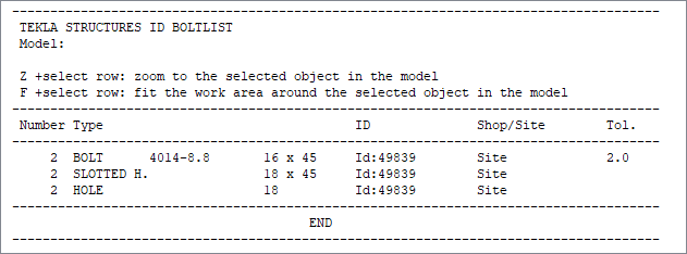
Report id_bolt_hole_list has been modified so that the bolts and the various types of holes (tapped holes, slotted holes, normal holes) are now shown separately in the report:
Image
In addition, the report id_longhole has been modified. This report shows all slotted holes whose spacing between the two circles of a slotted hole is less than or equal to 2 mm, this with respect to production purposes (breaking off the drill bit). So in the example below, the slotted hole with the spacing of 12 mm is not shown on the list, the other two slotted holes are shown:
Image

In the conditions in the report id_longhole (in the Template Editor) now the new template attributes are used.
Click here for more detailed information about the new template attributes.
Personal reports
If you modified the report id_longhole or id_bolt_hole_list in earlier Tekla Structures versions or you created such a report yourself, modify the conditions by using the new template attributes.
Click here for detailed information about the offset for slotted holes.
Click here for a YouTube video about the new options for slotted holes (and tapped holes).
Modeling bolts: New options for tapped holes
Earlier Tekla Structures versions
To model tapped holes in earlier Tekla Structures versions, you had the option to model two separate bolt groups.
Tekla Structures 2023
In Tekla Structures 2023 you can model tapped holes direct by using the command Bolt.
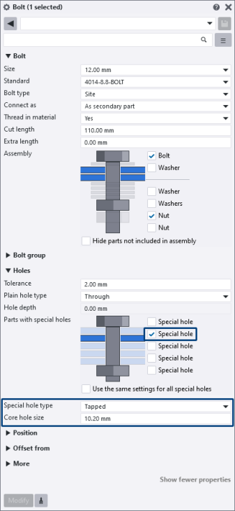
A new Special hole type option, Tapped, and the Core hole size box have been added to the Bolt properties:
Image

In Core hole size, you can define the predrilling hole size for a tapped hole. In the default setting tapped hole M12, this modification has been made.
Example
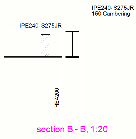
A column (RHS profile) to which a RHS profile with a welded end plate is connected. The end plate has holes, the column has tapped holes:
Image

Image
The bolt group is created where in this case the plate is selected first and next the column. Mind that the order of the special holes is related to the head of the bolt and not to the selection order.
Suppose the column was selected first and next the plate:
Image

Then the first special hole is in the plate because the head of the bolt is located there. If you rotate the bolt group 180 degrees, then the first special hole is in the column.
Tapped holes can also be created using system and custom components.
Filtering tapped holes
Because of the new options for tapped holes, a new selection filter tapped holes is available:
Image

The selection filter works for tapped holes that are in the bolt group, so even if, for example, there is a normal hole or a slotted hole in the bolt group:
Image

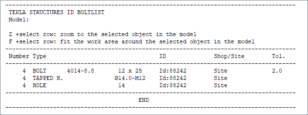
Tapped holes in reports
Report id_bolt_hole_list has been modified so that the bolts and various types of holes (tapped holes, slotted holes, normal holes) are now shown separately in the report:
Image
Tapped holes in drawings
We go back to the above example of the column to which a RHS profile with a welded end plate is connected. The end plate has holes, the column has tapped holes:
Image

To ensure that tapped holes Ø10.2 were provided with the correct symbol and label in earlier Tekla Structures versions in drawings, detailed object level setting tapgat was available:
Image

This setting was supplied by default for single-part and assembly drawings.
This setting has been deleted in Tekla Structures 2023 and you now have the following symbol and label by default:
Image

The symbol is "hard-coded." If you want to use another symbol, you can set it with a detailed object level setting as you could in earlier Tekla Structures versions.
You can customize the content of the hole label using the following four new advanced options available in the Advanced Options:
XS_SHOP_TAPPEDHOLE_MARK_STRING_FOR_SIZE
XS_SHOP_TAPPEDHOLE_MARK_STRING_FOR_SIZE_IN_GA
XS_SITE_TAPPEDHOLE_MARK_STRING_FOR_SIZE
XS_SITE_TAPPEDHOLE_MARK_STRING_FOR_SIZE_IN_GA
By default, the advanced options are all set to:
%BOLT_NUMBER%*\216%HOLE.DIAMETER.1% TAP M%BOLT_DIAMETER%
Here, the size of the tapped hole has 1 decimal character by default.
For the assembly drawings, when you create assembly drawings of parts with sinkholes in Tekla Structures 2023, the detailed object level setting sinkhole is applied by default.
Earlier Tekla Structures versions:
Image

Tekla Structures 2023:
Image

Tapped holes in DSTV NC files
If you had created DSTV NC files of parts with tapped holes in earlier Tekla Structures versions, you could convert these tapped holes (using the DSTV converter tool).
A configuration file was used to add the correct diameter and a g code (g stands for gewinde which means thread in German) indicating that thread should be added:
Image

In Tekla Structures 2023, you no longer need to convert the DSTV NC files of parts with tapped holes: the tapped hole information is now automatically exported to DSTV NC files.
Tapped holes in DXF files
Since the inner diameter is not available in DSTV NC files, it is also not available for conversion to DXF files. If applicable, you need to modify/update the DXF files yourself.
Click here for a YouTube video about the new options for tapped holes (and slotted holes).
System components
Help files for Construsoft components
By default, you have a large number of Tekla system components in Tekla Structures that have a Help file:
Image

In addition, Tekla Structures includes a large number of components from Construsoft (after installing the Construsoft developments) and many of these components also include a new or updated Help file by now:
Image

Image

The Help files contain detailed explanations of how the component works and additional practical examples.
Image

In the future, more and more Construsoft components will have these Help files.
Because the new Help files are available as articles in the Tekla User Assistance, a number of "old" Help files have been removed in Tekla Structures 2023.
These were so-called *.chm files and were stored in the folder ..:\TeklaStructures\<version>\Help\enu.
Stiffened end plate (27)
In system component Stiffened end plate (27), weld number 3 is now used for welding the end plate to the connecting RHS profiles:
Image

As a result, the following settings have been adjusted:
Image

Image

Personal settings
In case you have made personal settings in earlier Tekla Structures versions for system component Stiffened end plate (27), do the following:
1. Copy the personal component settings to Tekla Structures 2023, for example to the TS folder or to your model template.
2. Open Tekla Structures 2023 and select a personal setting from the drop-down list in the Stiffened end plate (27) dialog box (27).
3. Set weld number 3 and save the setting(s) again by using the Save As button.
Stiffened end plate (27) and Stiffened end plate (65) in column - beam connections
In addition, since Tekla Structures 2021, the functioning of the system components Stiffened end plate (27) and Stiffened end plate (65) has been slightly modified. The changes aim to make the system components more suitable for column - beam connections.
Advanced Model Labels (ML078)
Tekla Structures includes system component Advanced Model Labels (ML078) to position a model label in the model view. As a user, you can determine both the content and the selection. In earlier Tekla Structures versions, this tool worked for parts/assemblies and reinforcement.
Image

Image

The component has been extended in Tekla Structures 2023 so that you can now use labels for bolts:
Image

Stairs (S82)
In earlier Tekla Structures versions, system component Stairs (S82) was included:
Image

Image

This component is no longer available in Tekla Structures 2023.
After all, you have several very suitable system components in Tekla Structures with which you can model stairs including steps, for example system component Stairs (71).
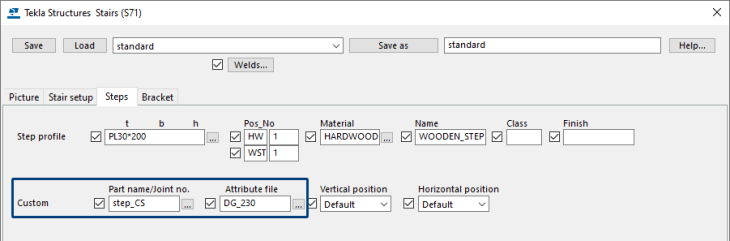
To be flexible in system component Stairs (71), Tekla Structures includes custom component step_CS by default, with which you can model steps manually or apply them in system components, such as in system component Stairs (71).
The big advantage is that in custom component step_CS you can store all desired types of steps as settings so that you are not dependent on changes in the range of suppliers:
Image

Image

Next you can apply the settings of custom component step_CS in system component Stairs (71):
Image
Image

Rebar assemblies available in several system components
In Tekla Structures 2022 rebar assemblies were introduced. These is a reinforcement object type that combines together any reinforcement object types. You can also include assemblies in rebar assemblies, and so add couplers, end anchors, and other parts as sub-assemblies. Rebar assemblies are useful when you model reinforcement cages or custom meshes that will be prefabricated, for example.
- Click here for detailed information about rebar assemblies and the new options and modifications that have been made in the Release Info (Chapter Modeling > Rebar assemblies (cages).
- Click here for detailed information about rebar assemblies in the Tekla Release Notes.
In Tekla Structures 2023, the following system components have the option for creating rebar assemblies:
- Embedded anchors (008)
- Round column reinforcement (82)
- Rectangular column reinforcement (83)
- Braced girder creation (88)
- Braced girder creation (89)
- Rebar in beam (90)
- Rebar in beam LT (91)
- Border rebar for single edge (93)
- Rectangular area reinforcement (94)
- Embed (1008)
- Mesh Bars
- Mesh Bars by Area
Image
In addition, rebar assemblies are now supported in the export to Unitechnik.
Personal settings
If you created settings for the above system components in earlier Tekla Structures versions, save these settings once again.
If desired, copy the new settings from the folder attributes in the model folder to your Tekla Structures 2023 TS folder or to your model template so that they are available in all models.
Rebar in beam (90) and Rebar in beam LT (91)
You now have the possibility in system component Rebar in beam (90) and Rebar in beam LT (91) to add stirrups in the "Cut zone" of a concrete element.
For example, to position stirrups on top of a cut zone:
Image

The corresponding option is available on the tab Stirrup spacing:
Image

Border rebar for single edge (93)
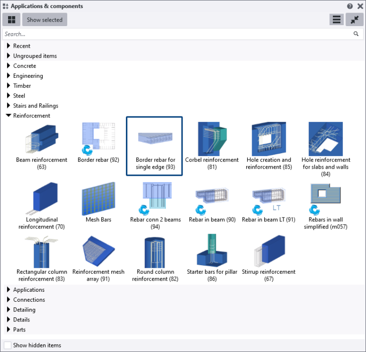
System component Border rebar for single edge (93) has been taken over by Tekla. This makes the component as follows available in the Applications and Components catalog:
Image

In the group Reinforcement in the Applications & components catalog only the Tekla system component is included by default:
Image
The name in the Applications & components catalog and the contents of the dialog boxes are the same for both system components:
Image

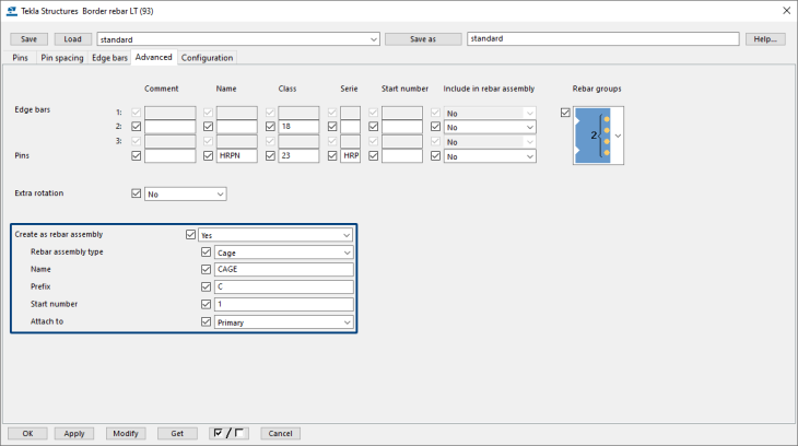
In addition, the available default settings were carried over from the Construsoft system component to the Tekla ones:
Image

Personal settings
If you have created personal settings for Construsoft system component Border rebar for single edge (93) and you want to be able to use these settings also in system component Border rebar for single edge (93) from Tekla, do the following:
1. Copy the personal Construsoft system component settings from an earlier Tekla Structures version to Tekla Structures 2023, for example to the TS folder or to your model template.
2. Go to the folder in which the settings are stored and rename the files with file extension *.m90000093 to *.m150000093.
|
Construsoft system component settings are stored as follows: <name_setting>.m90000093 So, the file extension is *.m90000093 |
|
Tekla system component settings are stored as follows: <name_setting>.m150000093 So, the file extension is *.m150000093 |
|
Image
 |
In Tekla Structures 2023, both system components are still available. In the future only the Tekla system component will still be available. You will of course be informed about this. |
Floor layout and wall layout
Command Floor layout and Wall layout nu include the new tab Properties in which you can select the required (pre-defined) IFC entity and the subtype. If desired, you can define a user-defined type.
Floor layout in Tekla Structures 2023:
Image

Wall layout in Tekla Structures 2023:
Image

Floor layout in earlier Tekla Structures versions:
Image

Wall layout in earlier Tekla Structures versions:
Image

General
Tekla Structures 2022 includes a number of improvements regarding to the IFC export to better comply with agreements regarding the exchange of information: for example, you now have more control over the object types for a better workflow when transferring information to the IFC4 format and you can define the necessary IFC entities more precisely with the new predefined and user-defined subtypes.
Personal settings
To ensure that your personal settings are appropriate for Tekla Structures 2023, do the following:
1. Copy the personal settings from an earlier Tekla Structures version to Tekla Structures 2023, for example to the TS folder or to your model template.
2. Open Tekla Structures 2023 and select a personal setting from the drop-down list in command Floor layout and/or Wall layout.
3. Set the desired fields for the IFC export (1) and possible additional settings and save the settings again (2):
Image

4. Copy the modified setting(s) to your TS folder or to your model template.
Drawings
New property pane in drawings
You already had a property pane for model objects in the Model Editor in earlier Tekla Structures versions:
Image

You now also have a property pane for object types in the Drawing Editor in Tekla Structures 2023:
Image

Click here for the list of object types for which the new properties dialog box is available.
Personal settings
To ensure that your personal settings are appropriate for Tekla Structures 2023, do the following:
1. Copy the personal settings from an earlier Tekla Structures version to Tekla Structures 2023, for example to the TS folder or to your model template.
2. Open Tekla Structures 2023 and select a personal setting from the drop-down list.
3. Check and modify (if needed) the setting(s) and save the setting(s) again.
Click here for detailed information in the Tekla Release Notes about the new property pane in drawings.
Click here for a YouTube video for detailed information.
Replace tables in drawing layout
With the new Layout editor context menu command Replace table you can replace tables in your layout.
To replace a table, right-click the table in the layout and select Replace table:
Image

Replacing a table preserves all the settings that you have defined for the table you replace.
The new command eliminates the need to first remove a table in the layout, then add a new template, set the anchor point and alignment, and finally connect other tables around the new one.
Part mark for base point coordinates added
In Tekla Structures, you can use base points. The base points (control points) allow you to use a coordinate system based on the civil origin or other coordinate system for interoperability and collaboration. For example, you can use base points when inserting reference models, exporting IFC models, in drawings, in Layout manager, and in reports and templates.
Now, a new part mark setting Base-point_Coordinates is added for base points:
Image

The coordinates applied here are based on the position of the base point.
Set base point
You can define the base point in the Model Editor via File > Project properties > Base points:
Image

In the Drawing Editor, you can set the base point via General arrangement drawing properties > View > Location by:
Image

Image

Tools/plug-ins
Write Numbering Results Into UDA (ML006)
In Tekla Structures you can use the tool Write Numbering Results Into UDA (ML006) for modifying prefixes and start numbers, writing numbering information to user defined attributes or copying main part profile properties to secondary (welded) parts.
Click here for detailed information about the usage of the tool Write Numbering Results Into UDA (ML006).
Tekla Structures 2023
Tekla Structures 2023 now includes the new option To Part (1) in tab UDA to write information from user defined attributes to the part properties Name, Profile, Material and Finish (2:
Image

Example
The following value for user defined attribute User field 1 (USER_FIELD_1) is set:
Image

In tool Write Numbering Results Into UDA (ML006) the following is set:
Image

Image

Image

Grating (m099)
In earlier Tekla Structures versions, you could use plug-in Grating (m099) in Tekla Warehouse to model advanced gratings and tear plates.
In Tekla Structures 2023, the plug-is available by default in the Applications & components catalog in the group Steel:
Image

The plug-in includes several options for adding openings and chamfers. You can also rotate the span direction and switch it on and off.
The gratings and tear plates are modeled as plates and they include a surface which means that they have a top and a bottom side. This is desirable for gratings and tear plates and this results in correct numbers.
You can use the command Direct modification in the plug-in to modify the dimensions of the grating and the contextual toolbar to modify the span direction, the thickness and the with.
By using plug-in Grating (m099), the drawings are clearer because of the types of surfaces:
Image

Model Drawing
In addition, you can use associated report grating-list:
Image

Click here for the Help of plug-in Grating (m099).
Convert Plate (m173)
Tekla Structures now includes system component Convert Plate (m173) and script Convert Plates (m173) to create a contour plate of a "beam" plate.
Image

With system component Convert Plate (m173) an extra plate will be created in the model with the same properties as the original plate. UDA's can be used to store info from the original part.
Script Convert Plates (m173) converts all beam plates into contour plates.
Click here for the Help.
Tekla Warehouse
Section views along path
In the Model Editor you can now have the tool Section views along path in Tekla Structures:
Image

The tool is used to create cross sections along the polycurve. The tool is available in Tekla Warehouse.
Image

Create Chamfer Symbols (DR075)
In drawings in earlier Tekla Structures versions, the tool Create Chamfer Symbols (DR075) was included by default:
Image

The name of the tool is now Edge chamfer annotation tool and is now available in Tekla Warehouse:
Image

This means that the tool is no longer available in Tekla Structures by default .
The tool Edge chamfer annotation tool can be used to create symbols on the edges of chamfers, or in the openings. You can define various types of symbols which can be used on various types of edges.
Personal settings
In case you had made personal settings in the tool Create Chamfer Symbols (DR075), you cannot use them in the new Edge chamfer annotation tool. You must redefine the settings in this tool.
Unify Bolt Holes
In Tekla Structures you can now have the tool Unify Bolt Holes in the Model Editor:
Image

The main purpose of the tool is to make parts identical by creating extra bolt holes with a common position for all selected beams. The tool is available in Tekla Warehouse.
Image
