Release Info Tekla Structures 2020
2020
Tekla Structures
Environment
Netherlands
Construsoft European
The Release Info Tekla Structures 2020 includes the following topics:
General
Tekla Structures 2020 video's
Tekla Structures 2020 provides many new options, improvements and fixes. These are all explained in this Release Info. Besides, some videos are available in which these functionalities are explained.

You can check the following videos (per segment):
Tekla Structures 2020 What's new for Steel
Tekla Structures 2020 What's new for Precast
Tekla Structures 2020 What's new for Structural Engineers
Tekla Structures 2020 What's new for Cast-in-place
Image

You can check the following videos (per segment):
Tekla Structures 2020 What's new for Steel
Tekla Structures 2020 What's new for Precast
Tekla Structures 2020 What's new for Structural Engineers
Tekla Structures 2020 What's new for Cast-in-place
Renewed logos in Tekla Structures 2020
Trimble has started to refresh logos, product icons, etc. for all brands within the Construction sector in 2020 to make the brand image consistent and clearer, along with the other brands they supply.
These changes have also been made in Tekla Structures 2020 so that you will find the renewed logo in many places, for example in drawings:

It is therefore possible that sometimes the old logo is still displayed in Tekla Structures 2020.
These changes have also been made in Tekla Structures 2020 so that you will find the renewed logo in many places, for example in drawings:
Image

It is therefore possible that sometimes the old logo is still displayed in Tekla Structures 2020.
Use separate ts folder per Tekla Structures version
For each Tekla Structures version, you have a ts folder where you can save custom settings so that they are available in all Tekla Structures models. The default location for the ts folder in Tekla Structures 2020 is:
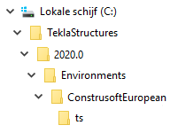
This location is defined by the advanced option
When multiple licenses are in use in one company, it is often desirable that everyone points to the same ts folder so that everyone uses the same profile catalog, drawing settings, templates, etc. In those cases, it is useful to have the ts folder located on a server.
This obviously promotes uniformity within the company. The advantage is that you only have to maintain one ts folder and after a change everyone is "up to date" immediately.
When working with different Tekla Structures versions, you always create a separate ts folder on the server for each Tekla Structures version. You do this because settings can differ per Tekla Structures version, for example due to new functionalities or changed user-defined attributes.

It is therefore preferable not to use settings of, for example, Tekla Structures 2019i in Tekla Structures 2020! Consider, for example, the settings (files) for the layout in drawings, see also chapter Drawings> Adjust drawing layouts with the improved Layout editor.
In addition, since Tekla Structures 2019i, you already had the option to use subfolders in the ts folder and save your own settings in these subfolders in order to organize them in a structured way and make them easier to manage.
Click here for more detailed information about creating project and firm folders.
Image

This location is defined by the advanced option
XS_FIRM in the Advanced options (via File > Settings > Advanced options).When multiple licenses are in use in one company, it is often desirable that everyone points to the same ts folder so that everyone uses the same profile catalog, drawing settings, templates, etc. In those cases, it is useful to have the ts folder located on a server.
This obviously promotes uniformity within the company. The advantage is that you only have to maintain one ts folder and after a change everyone is "up to date" immediately.
When working with different Tekla Structures versions, you always create a separate ts folder on the server for each Tekla Structures version. You do this because settings can differ per Tekla Structures version, for example due to new functionalities or changed user-defined attributes.
Image

It is therefore preferable not to use settings of, for example, Tekla Structures 2019i in Tekla Structures 2020! Consider, for example, the settings (files) for the layout in drawings, see also chapter Drawings> Adjust drawing layouts with the improved Layout editor.
In addition, since Tekla Structures 2019i, you already had the option to use subfolders in the ts folder and save your own settings in these subfolders in order to organize them in a structured way and make them easier to manage.
Click here for more detailed information about creating project and firm folders.
New user interface for rebar catalog
Tekla Structures 2020 introduces a new user interface for the rebar catalog (via File > Catalogs > Rebar catalog). The rebar catalog contains definitions for reinforcing bars and strands. You can add, modify and delete rebars in the catalog:

To edit reinforcing bars, you used the file rebar_database.inp file in earlier Tekla Structures versions. In Tekla Structures 2020, you can make changes in the new rebar catalog, which automatically updates the file rebar_database.inp.
The new rebar catalog is also being used when you select rebars in property dialog boxes:

Image

To edit reinforcing bars, you used the file rebar_database.inp file in earlier Tekla Structures versions. In Tekla Structures 2020, you can make changes in the new rebar catalog, which automatically updates the file rebar_database.inp.
The new rebar catalog is also being used when you select rebars in property dialog boxes:
Image

Updating model templates
In case you have created model templates in earlier Tekla Structures versions, you must update the templates to use them hassle-free in Tekla Structures 2020.
Click here for the general step plan.
Click here for the general step plan.
Copy customized ribbon and shortcuts to Tekla Structures 2020
You can copy your customized ribbon and shortcuts (after installing Tekla Structures 2020) from an older Tekla Structures version to Tekla Structures 2020.
Copy the ribbon
You can copy your customized ribbon from an older Tekla Structures version to Tekla Structures 2020.
If you copy your customized ribbon, new available (in Tekla Structures 2020) command buttons will be missing, for example the new command Rebar in the Drawing Editor for dimensioning rebar groups:

You can also first compare the "old" ribbon with the new "standard" ribbon in Tekla Structures 2020 via File> Settings> Ribbon> Compare in both Model and Drawing Editor:

You will see the differences between your customized ribbon and the "default" Tekla Structures 2020 ribbon, for example the new Rebar command:

You can now choose to add the missing command buttons or to use the new "standard" ribbon.
You can do next to copy your customized ribbon:
1. In the Windows Explorer, go to the folder (depends on the Tekla Structures-version)
or the folder
2. The *.xml file:
3. Copy this *.xml file to the folder
Click here for more detailed information about copying the ribbon.
Copy shortcuts
To copy shortcuts from an earlier Tekla Structures version to Tekla Structures 2020:
1. In an earlier Tekla Structures version, go to File > Settings > Keyboard shortcuts.
2. Click on the button Export, save the *.xml file on the desired location with the desired name.
3. In Tekla Structures 2020, go to File > Settings > Keyboard shortcuts.
4. Click on the button Import, select the *.xml file and click on the button Open, the shortcuts are now imported.
You can copy the exported *.xml file to any computer and next import the file in Tekla Structures 2020.
Copy the ribbon
You can copy your customized ribbon from an older Tekla Structures version to Tekla Structures 2020.
If you copy your customized ribbon, new available (in Tekla Structures 2020) command buttons will be missing, for example the new command Rebar in the Drawing Editor for dimensioning rebar groups:
Image

You can also first compare the "old" ribbon with the new "standard" ribbon in Tekla Structures 2020 via File> Settings> Ribbon> Compare in both Model and Drawing Editor:
Image

You will see the differences between your customized ribbon and the "default" Tekla Structures 2020 ribbon, for example the new Rebar command:
Image

You can now choose to add the missing command buttons or to use the new "standard" ribbon.
You can do next to copy your customized ribbon:
1. In the Windows Explorer, go to the folder (depends on the Tekla Structures-version)
C:\Users\<user>\AppData\Local\Trimble\TeklaStructures\<older version>\UI\Ribbons\ or the folder
C:\Users\<user>\AppData\Local\Trimble\Tekla Structures\<older version>\UI\Ribbons\2. The *.xml file:
albl_up_<license>--main_menu.xml contains the customized ribbon.3. Copy this *.xml file to the folder
C:\Users\<user>\AppData\Local\Trimble\Tekla Structures\2020.0\UI\Ribbons.Click here for more detailed information about copying the ribbon.
Copy shortcuts
To copy shortcuts from an earlier Tekla Structures version to Tekla Structures 2020:
1. In an earlier Tekla Structures version, go to File > Settings > Keyboard shortcuts.
2. Click on the button Export, save the *.xml file on the desired location with the desired name.
3. In Tekla Structures 2020, go to File > Settings > Keyboard shortcuts.
4. Click on the button Import, select the *.xml file and click on the button Open, the shortcuts are now imported.
You can copy the exported *.xml file to any computer and next import the file in Tekla Structures 2020.
New report castunit_sub-assemblylist and template Castunit_sub-assembly available
In Tekla Structures 2020 the new content type
The report and the template are intended for concrete subassemblies, for example a sandwich panel including a concrete subassembly:

... or a corbel that has been added as a subassembly to a concrete column (because the console will be poured later):

HIERARCHIC_CAST_UNIT is available for concrete subassemblies. Because of this, Tekla Structures now includes the new report castunit_sub-assemblylist and the template Castunit_sub-assembly.The report and the template are intended for concrete subassemblies, for example a sandwich panel including a concrete subassembly:
Image

... or a corbel that has been added as a subassembly to a concrete column (because the console will be poured later):
Image

New profiles added
Tekla has added two new parametric profiles, so Tekla Structures 2020 now includes the two following new profiles:
SLEEVEF2000*2000*500*500*1500*1500*800*800:

TPVAR170*260*900-350*400*1500:

SLEEVEF2000*2000*500*500*1500*1500*800*800:
Image

TPVAR170*260*900-350*400*1500:
Image

Update files and extensions from previous Tekla Structures versions
As a Tekla Structures user, you can use a checklist (installation log) that you may have created in a previous Tekla Structures version. Here you can document and save all your changes regarding Tekla Structures. After installing Tekla Structures 2020, you can quickly see what needs to be adjusted or checked so that you can get started with Tekla Structures 2020 quickly.
In addition, you can use the wizard Migration in Tekla Structures to copy various personal settings and extensions from a previous Tekla Structures version to Tekla Structures 2020. The wizard Migration opens automatically when you start Tekla Structures 2020 for the first time:

If you want to copy the settings later, you can start the wizard Migration manually by double-clicking the file MigrationWizard.exe in the folder ..\Tekla Structures\2020.0\nt\bin\applications\Tekla\Migrations or by searching in Tekla Structures for migration in the Quick Launch feature:

You can also use the Tekla Structures Extension Package (TSEP) builder and test runner (TeklaExtensionPackage.Builder.exe in the folder ..:/TeklaStructures/2020.0/nt/bin) for installing and/or deleting one or more extensions:

To install an extension in a selected Tekla Structures version:

... or delete several installed extensions very fast:

In addition, you can use the wizard Migration in Tekla Structures to copy various personal settings and extensions from a previous Tekla Structures version to Tekla Structures 2020. The wizard Migration opens automatically when you start Tekla Structures 2020 for the first time:
Image

If you want to copy the settings later, you can start the wizard Migration manually by double-clicking the file MigrationWizard.exe in the folder ..\Tekla Structures\2020.0\nt\bin\applications\Tekla\Migrations or by searching in Tekla Structures for migration in the Quick Launch feature:
Image

You can also use the Tekla Structures Extension Package (TSEP) builder and test runner (TeklaExtensionPackage.Builder.exe in the folder ..:/TeklaStructures/2020.0/nt/bin) for installing and/or deleting one or more extensions:
Image

To install an extension in a selected Tekla Structures version:
Image

... or delete several installed extensions very fast:
Image

Using predefined rules in the Template Editor
You can use several predefined rules (as a basis) in rows in the Template Editor.
Open the Template Editor (via File > Editors > Template Editor) in Tekla Structures and create or open an existing template/report and double-click on a row. The following dialog box appears:

Next click the button Advanced, you can now select predefined rules in the drop-down list:

When you select a line in the drop-down list, the content is shown immediately:

You can save your predefined rules (with adapted conditions) as follows:
Modify a condition and click button Store..., the following dialog box appears:

Enter the name for the predefined rule and click OK, the rule is now stored and visible in the drop-down list immediately:

All modifications are stored in the file rules.txt in the folder:
C:\TeklaStructures\2020.0\Environments\ConstrusoftEuropean\General\Template\settings
Restart Tekla Structures to be able to use the modifications in all Tekla Structures models.
Open the Template Editor (via File > Editors > Template Editor) in Tekla Structures and create or open an existing template/report and double-click on a row. The following dialog box appears:
Image

Next click the button Advanced, you can now select predefined rules in the drop-down list:
Image

When you select a line in the drop-down list, the content is shown immediately:
Image

You can save your predefined rules (with adapted conditions) as follows:
Modify a condition and click button Store..., the following dialog box appears:
Image

Enter the name for the predefined rule and click OK, the rule is now stored and visible in the drop-down list immediately:
Image

All modifications are stored in the file rules.txt in the folder:
C:\TeklaStructures\2020.0\Environments\ConstrusoftEuropean\General\Template\settings
Restart Tekla Structures to be able to use the modifications in all Tekla Structures models.
Interoperability
New point cloud settings and other improvements
You have the option to add point clouds in your Tekla Structures model since several Tekla Structures versions.
In Tekla Structures 2020, the side pane command Point clouds has been completely updated. The new point cloud functionalities are available when you have added a point cloud and when DirectX rendering (via File> Settings> DirectX rendering) is enabled:

You can now rotate and scale point clouds and adjust its location. To be able to change the values, you need to select the point cloud in the side pane.
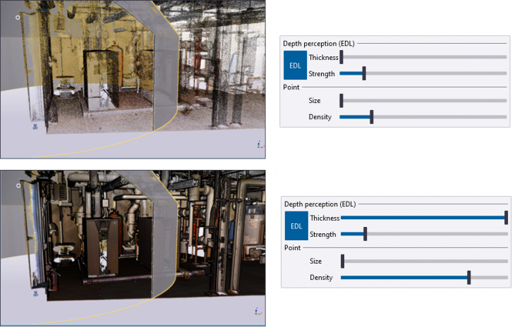
You can use EDL (Eye-dome lighting) effect to improve the depth perception of the point cloud. Drag the sliders to increase or decrease the outline thickness and strength of the point cloud. You can deactivate the EDL effect by clicking the EDL button:
You can also check clashes and deviations: Detect points that are inside or within a distance from the selected parts and selected reference models objects based on adjustable settings. Set the visualization setting to Clashes:

The interference between Tekla Structures objects and point clouds are visible in the model view using a color code where you can define the tolerance values yourself.
Click here for detailed information on the new point cloud settings and other improvements.
Click here for detailed information about point clouds.
In Tekla Structures 2020, the side pane command Point clouds has been completely updated. The new point cloud functionalities are available when you have added a point cloud and when DirectX rendering (via File> Settings> DirectX rendering) is enabled:
Image

You can now rotate and scale point clouds and adjust its location. To be able to change the values, you need to select the point cloud in the side pane.
You can use EDL (Eye-dome lighting) effect to improve the depth perception of the point cloud. Drag the sliders to increase or decrease the outline thickness and strength of the point cloud. You can deactivate the EDL effect by clicking the EDL button:
Image

You can also check clashes and deviations: Detect points that are inside or within a distance from the selected parts and selected reference models objects based on adjustable settings. Set the visualization setting to Clashes:
Image

The interference between Tekla Structures objects and point clouds are visible in the model view using a color code where you can define the tolerance values yourself.
Click here for detailed information on the new point cloud settings and other improvements.
Click here for detailed information about point clouds.
Export grid to IFC by default
Tekla Structures includes the option to export your Tekla Structures model to IFC by default via File> Export> IFC, the Export to IFC dialog box appears:
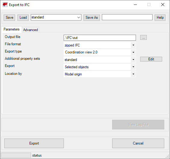
On the Parameters and Advanced tabs, you can define the details for the Tekla Structures model to be exported to an IFC file.
In Tekla Structures 2020, on the Advanced tab, the check box Grid is now selected by default so that grids in the Tekla Structures model are included in the export to IFC by default:

Image

On the Parameters and Advanced tabs, you can define the details for the Tekla Structures model to be exported to an IFC file.
In Tekla Structures 2020, on the Advanced tab, the check box Grid is now selected by default so that grids in the Tekla Structures model are included in the export to IFC by default:
Image

Trimble Connect Business-license for Tekla Structures users
At the end of 2019, Trimble announced that from 2020 it is not possible anymore to download Tekla BIMsight (as project collaboration software) and that support and developments will no longer take place. The main reason for the end of Tekla BIMsight is Trimble Connect.

Trimble Connect enables collaboration for engineering and construction projects, local and via cloud service, and is accessible via Desktop, Mobile or Web. Trimble Connect allows you to view, share, and access project information from anywhere at any time. You can combine 2D and 3D file formats, such as IFC, STEP, DWG and SKP. You can even add annotations in Trimble Connect.
It is no problem if you want to continue using Tekla BIMsight. You can still export your Tekla Structures model to an IFC file and open it in Tekla BIMsight. However, you can also choose to open your current Tekla BIMsight projects in Trimble Connect.
As of this year, you will receive a free Trimble Connect Business license with your Tekla Structures maintenance license. You can use this license by yourself or assign it to a colleague within your company. The free Trimble Connect Business version includes the following features:
- The extension Linking Documents to Trimble Connect, available in Tekla Warehouse.
- Defining property sets (such as production status, transport status) and the object browser: Click here for an instruction video.
- Trimble Connect Visualizer

Click here for more information to start working Trimble Connect.
Image

Trimble Connect enables collaboration for engineering and construction projects, local and via cloud service, and is accessible via Desktop, Mobile or Web. Trimble Connect allows you to view, share, and access project information from anywhere at any time. You can combine 2D and 3D file formats, such as IFC, STEP, DWG and SKP. You can even add annotations in Trimble Connect.
It is no problem if you want to continue using Tekla BIMsight. You can still export your Tekla Structures model to an IFC file and open it in Tekla BIMsight. However, you can also choose to open your current Tekla BIMsight projects in Trimble Connect.
As of this year, you will receive a free Trimble Connect Business license with your Tekla Structures maintenance license. You can use this license by yourself or assign it to a colleague within your company. The free Trimble Connect Business version includes the following features:
- The extension Linking Documents to Trimble Connect, available in Tekla Warehouse.
- Defining property sets (such as production status, transport status) and the object browser: Click here for an instruction video.
- Trimble Connect Visualizer
Image
Click here for more information to start working Trimble Connect.
Collaboration between Tekla Structures and Trimble Connect
Tekla Structures includes many improvements regarding to the collaboration between Tekla Structures models and Trimble Connect-projects.
1. Link Trimble Connect project in Tekla Structures 2020
You can now link your Tekla Structures model to a Trimble Connect project either right away while you are creating a new model by selecting the Start Trimble Connect collaboration check box on the start screen:

To link an open model to a Trimble Connect project, on the File menu, select Start collaboration.
In both cases, the Trimble Connect - Select project dialog box opens. Here, you can select if you want to link your model to a new Trimble Connect project or an existing one:

2. New buttons on the tab Trimble Connect in the ribbon
The tab Trimble Connect includes many new buttons that make it quicker and easier for the collaboration between Tekla Structures and Trimble Connect:

Click here for detailed information about the new buttons in the tab Trimble Connect in the ribbon.
3. New Connect overlay models
You can now use overlay models in Tekla Structures 2020.
An overlay model is a lightweight reference model that is stored in a Trimble Connect project. Overlay models show model objects, parts, rebars, bolts, and assemblies on top of Tekla Structures models. However, pours and pour units are not shown. You can attach overlay models to your Tekla Structures model, view the attached overlay models in a clear tree structure, and manage overlay models in several ways.
To start managing overlay models:
► Click Models
 on the tab Trimble Connect and ensure that the Overlay models tab is open:

Here, you can:
- Hide or show overlay models by clicking the
 and
and
 icons.
- Adjust the scale and position of overlay models in the Properties section.
Export Tekla Structures models to Trimble Connect
To export Tekla Structures models to Trimble Connect, you export your Tekla Structures model to IFC and next open it in Trimble Connect:

NOTE: You also have the command in Tekla Structures to export directly to Trimble Connect via File > Export > Trimble Connect. However, you do not use this command; you follow the step-by-step plan below.
The following Trimble Connect versions are available in Tekla Structures (you possibly need to log in with your Trimble Identity):
- Trimble Connect 3D Viewer
 , this is the online version.
- Trimble Connect Desktop
 , click here for the download. Click here for an instruction video about Trimble Connect Desktop.
Step plan
1. Open a Tekla Structures-model.
2. Before exporting the Tekla Structures model, check whether the parts you want to export, include the correct IFC-entity and IFC-export type.
3. If needed, create a base point in your model for the IFC file, click here for more detailed information.
4. Select the entire model or select the model objects that you want to export.
5. Click File > Export > IFC, dialog box Export to IFC appears:

6. If needed, you can define property set configuration files (field Additional property sets) besides the predefined property set configuration files to define which user-defined attributes are exported as property sets into IFC models. Click here for more detailed information.
7. Click Export, the IFC file is created and stored in the model folder by default.
8. Open Trimble Connect, if needed log in with your Trimble Identity.
9. Link the Tekla Structures model to a Trimble Connect-project:

10. Next add the IFC file to the project by dragging it from the Windows Explorer into Trimble Connect:

11. Double-click on the button View to open the IFC file:

Click here for detailed information about Trimble Connect.
Click here for an instruction video about the collaboration between Tekla Structures and Trimble Connect.
Link documents from the Tekla Structures model to a Trimble Connect project
In Tekla Structures you can use the extension Linking Documents to Trimble Connect to links documents to a Trimble Connect project:

The extension is available in Tekla Warehouse and links from model objects in the Tekla Structures model single part-, assembly-, cast unit- and GA drawings, NC files and IFC files to the corresponding objects in the Trimble Connect project.

NOTE: The extension Linking Documents to Trimble Connect only works if you export IFC files from Tekla Structures and insert them into Trimble Connect, not if you exported directly from Tekla Structures to Trimble Connect (* .tekla file) via File > Export > Trimble Connect.
In addition, for the Linking Documents to Trimble Connect extension to work correctly, the following also applies:
When you create drawings in Tekla Structures, a snapshot of the drawings is automatically created. Every time you edit a drawing and save it, a new snapshot of the drawing is automatically saved. This applies to all drawing types. Two variables affect the creation of drawing snapshots:
If you switch off creating snapshots in Tekla Structures, a message appears asking you to set the advanced options to be able to export the drawings to Trimble Connect.
Click here for detailed information about the usage of the extension Linking Documents to Trimble Connect.
1. Link Trimble Connect project in Tekla Structures 2020
You can now link your Tekla Structures model to a Trimble Connect project either right away while you are creating a new model by selecting the Start Trimble Connect collaboration check box on the start screen:
Image

To link an open model to a Trimble Connect project, on the File menu, select Start collaboration.
In both cases, the Trimble Connect - Select project dialog box opens. Here, you can select if you want to link your model to a new Trimble Connect project or an existing one:
Image

2. New buttons on the tab Trimble Connect in the ribbon
The tab Trimble Connect includes many new buttons that make it quicker and easier for the collaboration between Tekla Structures and Trimble Connect:
Image

Click here for detailed information about the new buttons in the tab Trimble Connect in the ribbon.
3. New Connect overlay models
You can now use overlay models in Tekla Structures 2020.
An overlay model is a lightweight reference model that is stored in a Trimble Connect project. Overlay models show model objects, parts, rebars, bolts, and assemblies on top of Tekla Structures models. However, pours and pour units are not shown. You can attach overlay models to your Tekla Structures model, view the attached overlay models in a clear tree structure, and manage overlay models in several ways.
To start managing overlay models:
► Click Models
Image
Image

Here, you can:
- Hide or show overlay models by clicking the
Image
Image
- Adjust the scale and position of overlay models in the Properties section.
Export Tekla Structures models to Trimble Connect
To export Tekla Structures models to Trimble Connect, you export your Tekla Structures model to IFC and next open it in Trimble Connect:
Image

NOTE: You also have the command in Tekla Structures to export directly to Trimble Connect via File > Export > Trimble Connect. However, you do not use this command; you follow the step-by-step plan below.
The following Trimble Connect versions are available in Tekla Structures (you possibly need to log in with your Trimble Identity):
- Trimble Connect 3D Viewer
Image
- Trimble Connect Desktop
Image
Step plan
1. Open a Tekla Structures-model.
2. Before exporting the Tekla Structures model, check whether the parts you want to export, include the correct IFC-entity and IFC-export type.
3. If needed, create a base point in your model for the IFC file, click here for more detailed information.
4. Select the entire model or select the model objects that you want to export.
5. Click File > Export > IFC, dialog box Export to IFC appears:
Image

6. If needed, you can define property set configuration files (field Additional property sets) besides the predefined property set configuration files to define which user-defined attributes are exported as property sets into IFC models. Click here for more detailed information.
7. Click Export, the IFC file is created and stored in the model folder by default.
8. Open Trimble Connect, if needed log in with your Trimble Identity.
9. Link the Tekla Structures model to a Trimble Connect-project:
Image

10. Next add the IFC file to the project by dragging it from the Windows Explorer into Trimble Connect:
Image

11. Double-click on the button View to open the IFC file:
Image

Click here for detailed information about Trimble Connect.
Click here for an instruction video about the collaboration between Tekla Structures and Trimble Connect.
Link documents from the Tekla Structures model to a Trimble Connect project
In Tekla Structures you can use the extension Linking Documents to Trimble Connect to links documents to a Trimble Connect project:
Image

The extension is available in Tekla Warehouse and links from model objects in the Tekla Structures model single part-, assembly-, cast unit- and GA drawings, NC files and IFC files to the corresponding objects in the Trimble Connect project.
Image

NOTE: The extension Linking Documents to Trimble Connect only works if you export IFC files from Tekla Structures and insert them into Trimble Connect, not if you exported directly from Tekla Structures to Trimble Connect (* .tekla file) via File > Export > Trimble Connect.
In addition, for the Linking Documents to Trimble Connect extension to work correctly, the following also applies:
When you create drawings in Tekla Structures, a snapshot of the drawings is automatically created. Every time you edit a drawing and save it, a new snapshot of the drawing is automatically saved. This applies to all drawing types. Two variables affect the creation of drawing snapshots:
XS_DRAWING_CREATE_SNAPSHOT_ON_DRAWING_CREATION: This advanced option is set to TRUE by default to create a snapshot of a drawing at the same time that you create the drawing.XS_DRAWING_SNAPSHOT_CREATION: This advanced option is set to TRUE by default so that snapshots are created automatically when you save a drawing.If you switch off creating snapshots in Tekla Structures, a message appears asking you to set the advanced options to be able to export the drawings to Trimble Connect.
Click here for detailed information about the usage of the extension Linking Documents to Trimble Connect.
Modeling
Modeling curved shapes: improvements in lofted plates and lofted slabs
Tekla Structures 2019i introduced modeling new steel lofted plates and concrete lofted slabs by using construction objects:
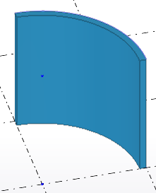
In Tekla Structures 2020, the creation of lofted plates and lofted slabs has been further enhanced and you can now model even more complex curved shapes by using polycurve construction objects:

Before creating lofted plates or lofted slabs, you need to have modeled polycurve construction objects. Tekla Structures creates the shape of the lofted part according to the geometry of the polycurve construction objects.

Additionally, you can now unfold lofted plates in single-part drawings:

Click here for more detailed information about modeling lofted plates and lofted slabs.
| Two construction lines | A construction line and a construction arc |
Two construction arc | Two construction circles | A construction object and a point |
|
Image
 |
Image
 |
Image
 |
Image
 |
Image
 |
In Tekla Structures 2020, the creation of lofted plates and lofted slabs has been further enhanced and you can now model even more complex curved shapes by using polycurve construction objects:
Image

Before creating lofted plates or lofted slabs, you need to have modeled polycurve construction objects. Tekla Structures creates the shape of the lofted part according to the geometry of the polycurve construction objects.
Image

Additionally, you can now unfold lofted plates in single-part drawings:
Image

Click here for more detailed information about modeling lofted plates and lofted slabs.
Part representation in model views
In Tekla Structures 2020, the DirectX rendered model views (via File > Settings > DirectX-rendering) have been improved.
Part edge lines are shown as dashed lines in transparent model views
In DirectX rendered model views, the part edge lines that are hidden behind another part are now shown as dashed lines in all transparent views whose rendering option is one of the following:
(Tekla Structures rendering can use either DirectX or OpenGL technology. To improve the rendering quality, you can set Tekla Structures to use the DirectX rendering engine instead of the default OpenGL-based rendering engine. The DirectX rendering adds a subtle shading effect to Tekla Structures objects, making the 3D visualizations clearer and more defined).
If you want to show the part hidden lines in DirectX rendered views, set the advanced option

The advanced option is set to

Model objects have thicker edge lines
In DirectX rendered model views, all model objects, except reinforcing bars, have thicker edge lines than previously. The edge lines for reinforcing bars remain the same as they have previously been. This change improves the previously experienced blurriness of edge lines.
Anti-aliasing in DirectX-rendered views
Anti-aliasing is now on by default in DirectX rendered views. The advanced option XS_USE_ANTI_ALIASING_IN_DX is set to TRUE by default. Previously, the default value was FALSE.
Click here for more information about the advanced option
Click here for more information about changing the rendering mode.
Part edge lines are shown as dashed lines in transparent model views
In DirectX rendered model views, the part edge lines that are hidden behind another part are now shown as dashed lines in all transparent views whose rendering option is one of the following:
| Part representation | Shortcut combination |
| Parts wireframe | Ctrl + 1 |
| Parts shaded wireframe | Ctrl + 2 |
| Parts greyscale | Ctrl + 3 |
| Show only selected parts | Ctrl + 5 |
| Component part representation | Shortcut combination |
| Components wireframe | Shift + 1 |
| Components shaded wireframe | Shift + 2 |
| Components greyscale | Shift + 3 |
| Show only selected components | Shift + 5 |
(Tekla Structures rendering can use either DirectX or OpenGL technology. To improve the rendering quality, you can set Tekla Structures to use the DirectX rendering engine instead of the default OpenGL-based rendering engine. The DirectX rendering adds a subtle shading effect to Tekla Structures objects, making the 3D visualizations clearer and more defined).
If you want to show the part hidden lines in DirectX rendered views, set the advanced option
XS_USE_DASHED_HIDDEN_LINES to TRUE.Image

The advanced option is set to
FALSE not to show the part hidden lines:Image

Model objects have thicker edge lines
In DirectX rendered model views, all model objects, except reinforcing bars, have thicker edge lines than previously. The edge lines for reinforcing bars remain the same as they have previously been. This change improves the previously experienced blurriness of edge lines.
Anti-aliasing in DirectX-rendered views
Anti-aliasing is now on by default in DirectX rendered views. The advanced option XS_USE_ANTI_ALIASING_IN_DX is set to TRUE by default. Previously, the default value was FALSE.
Click here for more information about the advanced option
XS_USE_ANTI_ALIASING_IN_DX.Click here for more information about changing the rendering mode.
Sketch Solver package in Tekla Structures
Tekla Structures includes the Sketch Editor (via menu File > Catalogs > Define profiles > Define cross section in sketch editor) to define parametric profiles.
The following message appears when you start the Sketch Editor in Tekla Structures 2020 (and also in Tekla Structures 2019i):

The message tells you to install the so-called Sketch Solver package (this is an external library as a separate extension) to be able to keep defining or editing parametric profiles. The package is available in Tekla Warehouse.
When you edit sketched profiles in your Tekla Structures model or when you define new profiles, Tekla Structures checks whether the package is installed. If not, the message appears. After installing the extension, it all works in the same way as in earlier Tekla Structures versions.
When you define new sketched profiles in your Tekla Structures model, the file pgdb.bin is saved in the model folder.
The following message appears when you start the Sketch Editor in Tekla Structures 2020 (and also in Tekla Structures 2019i):
Image

The message tells you to install the so-called Sketch Solver package (this is an external library as a separate extension) to be able to keep defining or editing parametric profiles. The package is available in Tekla Warehouse.
When you edit sketched profiles in your Tekla Structures model or when you define new profiles, Tekla Structures checks whether the package is installed. If not, the message appears. After installing the extension, it all works in the same way as in earlier Tekla Structures versions.
When you define new sketched profiles in your Tekla Structures model, the file pgdb.bin is saved in the model folder.
Diagnose and list solid errors
The solid errors found in the currently open model are now shown in the report that opens when you use the Diagnose & repair > Diagnose model command on the File menu:

When you press and hold the Z key on your keyboard while selecting a line in the list, Tekla Structures automatically zooms in on the corresponding solid error in the active model view.
You can now solve the solid error in the model:

Image

When you press and hold the Z key on your keyboard while selecting a line in the list, Tekla Structures automatically zooms in on the corresponding solid error in the active model view.
You can now solve the solid error in the model:
Image

Improved representation for welded profiles in model views
Since Tekla Structures 2018i the representation for welded plates in model views has been improved: welded plates color light blue, loose plates don't:

Since Tekla Structures 2019, also the representation for welded RHS profiles has been improved:

and since Tekla Structures 2019i also the representation for welded L profiles has been improved:

In Tekla Structures 2020 the representation for welded U profiles has been improved:

Because of these modifications, the setting standard looks as follows:

The object group welded U looks as follows:

so that welded U-profiles (1) with the name that is equal to, for example STRINGER, do not have this representation:

Also the setting only steel now includes these object groups (1) for the representation of welded parts:

In addition, in the setting only steel is defined that parts that have the material quality cast in place, precast and timber, are invisible (2) so that only the steel is displayed.
For representing bolts in Tekla Structures 2020, the setting bolts color is added:

In addition to the object groups for the welded parts (1), the setting bolts color includes a definition for bolts with a diameter smaller than 16 mm shown in yellow and a definition for bolts with a diameter larger than 16 mm are shown in magenta (2). Bolts with a diameter equal to 16 mm are represented in the default (brown) color:

Also the settings length assembly and length part are added:

The settings define the length of assemblies and parts: assemblies/parts that are longer than 24 meters are shown in red. The other model objects are (temporarily) hidden.
If desired, you can of course customize the model view settings to your needs.
Image

Since Tekla Structures 2019, also the representation for welded RHS profiles has been improved:
Image

and since Tekla Structures 2019i also the representation for welded L profiles has been improved:
Image

In Tekla Structures 2020 the representation for welded U profiles has been improved:
Image

Because of these modifications, the setting standard looks as follows:
Image

The object group welded U looks as follows:
Image

so that welded U-profiles (1) with the name that is equal to, for example STRINGER, do not have this representation:
Image

Also the setting only steel now includes these object groups (1) for the representation of welded parts:
Image

In addition, in the setting only steel is defined that parts that have the material quality cast in place, precast and timber, are invisible (2) so that only the steel is displayed.
For representing bolts in Tekla Structures 2020, the setting bolts color is added:
Image

In addition to the object groups for the welded parts (1), the setting bolts color includes a definition for bolts with a diameter smaller than 16 mm shown in yellow and a definition for bolts with a diameter larger than 16 mm are shown in magenta (2). Bolts with a diameter equal to 16 mm are represented in the default (brown) color:
Image

Also the settings length assembly and length part are added:
Image

The settings define the length of assemblies and parts: assemblies/parts that are longer than 24 meters are shown in red. The other model objects are (temporarily) hidden.
If desired, you can of course customize the model view settings to your needs.
Show and modify drawing views in the model
You can show the drawing views of the selected drawings in any of the open model views to get a clearer understanding of exactly where a drawing view is located in the 3D model, the view direction, and the 3D extents of that view.
Show the drawing views in model views
1. In the modeling mode, go to the tab Drawings & reports, open the Document manager and select one or more drawings in the document list.
2. Next click the Show drawing views in the model button in the top-right corner of the Document manager window. When this button is activated, it changes color:

The views in the selected drawings are now displayed in the model. You can then use direct modification to work with the view extents and view plane of every view that is contained within each selected drawing in the currently open model views.
When Show drawing views in the model is active, any changes to the selection of drawings will cause the Show drawing views in the model command to be automatically re-run. This way you can easily walk through a list of drawings, selecting one drawing at a time, and see the views for that drawing in the model:

__________________________________________________________________________________________________________

Labels show the name of each drawing view in the model when you move the mouse pointer over an unselected view edge or when a view is selected.
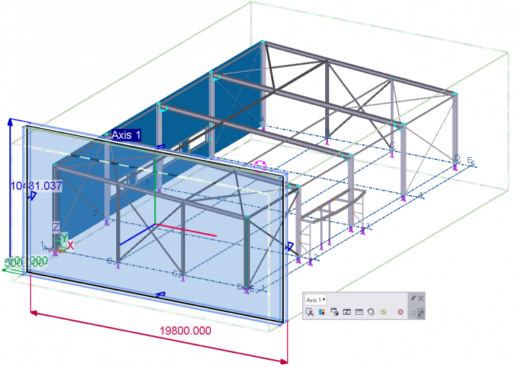
Next you can make all kinds of changes in the model view of interest to automatically make the changes in the drawing view, for example the rotation of a 3D view.
Click here for detailed information about showing and modifying drawing views in a model.
Show the drawing views in model views
1. In the modeling mode, go to the tab Drawings & reports, open the Document manager and select one or more drawings in the document list.
2. Next click the Show drawing views in the model button in the top-right corner of the Document manager window. When this button is activated, it changes color:
Image
The views in the selected drawings are now displayed in the model. You can then use direct modification to work with the view extents and view plane of every view that is contained within each selected drawing in the currently open model views.
When Show drawing views in the model is active, any changes to the selection of drawings will cause the Show drawing views in the model command to be automatically re-run. This way you can easily walk through a list of drawings, selecting one drawing at a time, and see the views for that drawing in the model:
Image

__________________________________________________________________________________________________________
Image

Labels show the name of each drawing view in the model when you move the mouse pointer over an unselected view edge or when a view is selected.
Image

Next you can make all kinds of changes in the model view of interest to automatically make the changes in the drawing view, for example the rotation of a 3D view.
Click here for detailed information about showing and modifying drawing views in a model.
System components
Modeling steps
Tekla Structures includes several system components for modeling stairs including steps, for example system component Stairs (71). Previously, in this system component, a step catalog could be used for modeling steps:

This step catalog includes many common step profiles of suppliers by default.
However, it is of course possible that changes take place in the steps, for example changes in the shape or the dimensions, or steps that are no longer available, etc. In order to provide Tekla Structures users with a current step catalog, suppliers more often make their products also available on Tekla Warehouse.
As a Tekla Structures user, you may have been using this steps catalog for years, knowing that the types of steps you use exist and that these types of steps are available. In that case it is of course no problem to use and continue using this catalog.
The step catalog is not available in Tekla Structures 2020 by default anymore, you can do next to be able to use the step catalog again:
1. Close Tekla Structures 2020.
2. Open the Windows Explorer and go to the folder C:\TeklaStructures\2020.0\applications\steel1
3. Delete the file ts_page_10_construsofteuropean.inp.
4. Select the file ts_page_10_construsofteuropean - kopie.inp and rename the file to ts_page_10_construsofteuropean.inp.
5. Start Tekla Structures2020, the step catalog is available again.
You possibly exchange Tekla Structures models in which you or other Tekla Structures users have used steps from the steps catalog. If you or the recipient of your model did not have this step database, the model would not be complete.
However, in order to be more flexible, Tekla Structures includes custom component step for many years that allows you to model steps manually or use them in system components:

Custom component step is available in Tekla Structures by default and has the great advantage that you can save all desired types of steps. Because of that, you are no longer dependent on changes in the assortment of suppliers.
The corresponding stair-steplist has been renamed to step list. Custom component step has been adjusted so that now only the name of the supplier is shown in the list:

In earlier Tekla Structures versions also the width of the steps was represented.
Image

This step catalog includes many common step profiles of suppliers by default.
However, it is of course possible that changes take place in the steps, for example changes in the shape or the dimensions, or steps that are no longer available, etc. In order to provide Tekla Structures users with a current step catalog, suppliers more often make their products also available on Tekla Warehouse.
As a Tekla Structures user, you may have been using this steps catalog for years, knowing that the types of steps you use exist and that these types of steps are available. In that case it is of course no problem to use and continue using this catalog.
The step catalog is not available in Tekla Structures 2020 by default anymore, you can do next to be able to use the step catalog again:
1. Close Tekla Structures 2020.
2. Open the Windows Explorer and go to the folder C:\TeklaStructures\2020.0\applications\steel1
3. Delete the file ts_page_10_construsofteuropean.inp.
4. Select the file ts_page_10_construsofteuropean - kopie.inp and rename the file to ts_page_10_construsofteuropean.inp.
5. Start Tekla Structures2020, the step catalog is available again.
You possibly exchange Tekla Structures models in which you or other Tekla Structures users have used steps from the steps catalog. If you or the recipient of your model did not have this step database, the model would not be complete.
However, in order to be more flexible, Tekla Structures includes custom component step for many years that allows you to model steps manually or use them in system components:
Image

Custom component step is available in Tekla Structures by default and has the great advantage that you can save all desired types of steps. Because of that, you are no longer dependent on changes in the assortment of suppliers.
The corresponding stair-steplist has been renamed to step list. Custom component step has been adjusted so that now only the name of the supplier is shown in the list:
Image

In earlier Tekla Structures versions also the width of the steps was represented.
New formwork placing tools for walls and slabs available
Tekla Structures 2020 includes new formwork placing tools: Formwork placing tools - Walls and Formwork placing tools - Slabs. Previously, these tools have been available in Tekla Warehouse.
The formwork placing tools enable the efficient modeling of different wall panel and slab panel formwork systems.
The formwork placing tools are available in the All, Cast-in-place and Contractor roles. The tools Wall and Slab are placed on the Formwork tab in the ribbon:

and the individual sub-components included in the tools are available in the Applications and components catalog:

The formwork placing tools enable the efficient modeling of different wall panel and slab panel formwork systems.
The formwork placing tools are available in the All, Cast-in-place and Contractor roles. The tools Wall and Slab are placed on the Formwork tab in the ribbon:
Image

and the individual sub-components included in the tools are available in the Applications and components catalog:
Image

Online Help files available for Construsoft system components
System component Footplate (1029), Bolts between points (m093) and Wooden purlin (1) from Construsoft now include an (online) Help file:


The Help files are located in the Tekla User Assistance and therefore online available. The main advantage of this is that if the system components have new functionalities, the Help files can be modified (updated) very quickly and are therefore immediately up to date (because they are online).
More and more Construsoft system component Help files will become available online in the future.
Image

Image

The Help files are located in the Tekla User Assistance and therefore online available. The main advantage of this is that if the system components have new functionalities, the Help files can be modified (updated) very quickly and are therefore immediately up to date (because they are online).
More and more Construsoft system component Help files will become available online in the future.
Wood wall (57)
System component Wood wall (57) now includes several improvements:
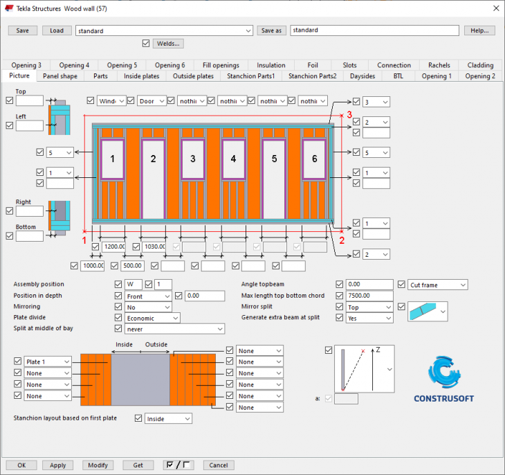
You can now set the zone of H-frames of the opening and you can control the zone. In addition, you can now apply different starting positions on both sides of the element, whereby the position of the stud determines the next seam for the plate.
Image

You can now set the zone of H-frames of the opening and you can control the zone. In addition, you can now apply different starting positions on both sides of the element, whereby the position of the stud determines the next seam for the plate.
Wooden roof (63)
System component Wooden roof (63) now includes the following improvement:

If you now use the default set names in system component Wooden roof (63) for cladding and for rafters, the new settings for the dimensions will work for all zones.
In addition, the names of negative volumes have now been improved for correct export to BVX files.
Click here for guidelines (in English) that apply for detailing wooden parts for suitable production data for wood framing machines.
Image

If you now use the default set names in system component Wooden roof (63) for cladding and for rafters, the new settings for the dimensions will work for all zones.
In addition, the names of negative volumes have now been improved for correct export to BVX files.
Click here for guidelines (in English) that apply for detailing wooden parts for suitable production data for wood framing machines.
Tube-tube with weld preparation (63)
System component Tube-tube with weld preparation (63) includes a new option for the secondary tube:


Image

Image

Rebar in beam (90) and Rebar in beam LT (91)
System components Rebar in beam (90) and Rebar in beamer LT (91) now includes a new drop-down list in the tabs Primary bottom bars, Primary top bars, Side left and Side right:

You can use the options in the drop-down list to define the position of the hairpins and the main rebars relative to each other:
Image

You can use the options in the drop-down list to define the position of the hairpins and the main rebars relative to each other:
|
Image
|
Image
 |
Image
 |
|
Image
|
Image
 |
Image
 |
|
Image
|
Image
 |
Image
 |
Tube - tube (109)
Tekla Structures includes system component Tube - tube (109) for creating a (welded) connection between two tube profiles:

The system component includes a new option in Tekla Structures 2020 to cut the secondary tube profile and to define the desired angle(s):

For more detailed information about the using the system component, click the Help button in system components dialog box.
Image

The system component includes a new option in Tekla Structures 2020 to cut the secondary tube profile and to define the desired angle(s):
Image

For more detailed information about the using the system component, click the Help button in system components dialog box.
Floor Layout
System component Floor Layout includes several improvements.
In previous Tekla Structures versions, system component Floor Layout CIP filler properties was included to fill seam gaps between hollow core slabs:

This component is not included in Tekla Structures 2020 anymore because this option is now available in the new tab CIP filler part in system component Floor Layout:

Set the options Create filler parts and Fill seam gaps to Yes to fill the seam gaps:

You also use the option Create filler parts when you use the new options (1) on the tab Advanced to define the conditions for detailing the hollow core slabs:

In addition, on the Advanced tab, you have options to define classes (colors) for parts that cut hollow core slabs and that you want to give a clearance:
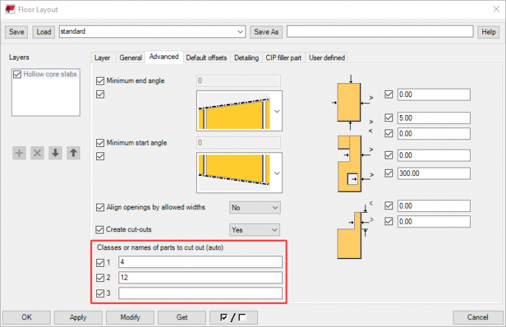
The classes you enter automatically appear on the Default offsets tab where you can define the size of the clearance:


In previous Tekla Structures versions, system component Floor Layout CIP filler properties was included to fill seam gaps between hollow core slabs:
Image

This component is not included in Tekla Structures 2020 anymore because this option is now available in the new tab CIP filler part in system component Floor Layout:
Image

Set the options Create filler parts and Fill seam gaps to Yes to fill the seam gaps:
Image

You also use the option Create filler parts when you use the new options (1) on the tab Advanced to define the conditions for detailing the hollow core slabs:
Image

| Create filler parts No |
Image
 |
Image
 |
| Create filler parts No |
Image
 |
Image
 |
| Create filler parts Yes |
Image
 |
Image
 |
In addition, on the Advanced tab, you have options to define classes (colors) for parts that cut hollow core slabs and that you want to give a clearance:
Image

The classes you enter automatically appear on the Default offsets tab where you can define the size of the clearance:
Image

Image

Wall layout connector
Tekla Structures includes system component Wall layout connector, which you can use combined with the wall layout tools, for connecting walls to each other. The system component is improved and now includes a new button for detailing the shells at the edge connection:


Image

Image

Custom components
Availability of custom components
In Tekla Structures 2020 the availability for custom components has changed.
The availability depends on the so-called "role" with which you start Tekla Structures. These roles have been modified so that you now only have a few obvious custom components.
For example, customers who start Tekla Structures with the Steel Detailer role now have a steel-related custom component and a few general custom components by default. They therefore do not have default wood and/or concrete-related custom components.
In Windows Explorer:

In Tekla Structures:

To have all other available custom components, you can import them in Tekla Structures in the usual way.
The availability depends on the so-called "role" with which you start Tekla Structures. These roles have been modified so that you now only have a few obvious custom components.
For example, customers who start Tekla Structures with the Steel Detailer role now have a steel-related custom component and a few general custom components by default. They therefore do not have default wood and/or concrete-related custom components.
In Windows Explorer:
Image

In Tekla Structures:
Image

To have all other available custom components, you can import them in Tekla Structures in the usual way.
Drawings
Improved drawing performance
The performance of the drawings has been improved in Tekla Structures 2020. The improvements affect drawing opening time, zoom performance, pan performance (dragging the drawing from one end of the screen to another) and drawing editing (adding add marks, text, lines, and moving views, among other things).
The advanced option
The advanced option
XS_USE_SMART_PAN is now set to TRUE by default to be able to zoom and pan even faster. Improved settings for GA- and assembly drawings
GA drawings
Tekla Structures includes GA drawing setting 3D:

In this setting, the Filter defines which model objects are shown in general arrangement drawings:

Welded plates with the name PLATE are deliberately hidden because in GA drawings with scale 1: 100 or larger, it is not useful to show these plates.
In Tekla Structures 2020, this setting has been improved to also hide parts with the name STIF (stiffener), NUT and WASH (washer):

Tekla Structures 2019i and earlier versions:


Model GA drawing
Tekla Structures 2020:


Model GA drawing
This has also been improved on view level so that the setting 3D GA is now available:

Assembly drawings
For assembly drawings, the settings supplied by Construsoft have been adjusted:

All settings now include the setting 3d assembly in the button View:

for the representation of a 3D view in assembly drawings:


The setting 3d assembly does not use any filters so that all model objects of the assembly are shown in the drawing.
Tekla Structures includes GA drawing setting 3D:
Image

In this setting, the Filter defines which model objects are shown in general arrangement drawings:
Image

Welded plates with the name PLATE are deliberately hidden because in GA drawings with scale 1: 100 or larger, it is not useful to show these plates.
In Tekla Structures 2020, this setting has been improved to also hide parts with the name STIF (stiffener), NUT and WASH (washer):
Image

Tekla Structures 2019i and earlier versions:
Image

Image

Model GA drawing
Tekla Structures 2020:
Image

Image

Model GA drawing
This has also been improved on view level so that the setting 3D GA is now available:
Image

Assembly drawings
For assembly drawings, the settings supplied by Construsoft have been adjusted:
Image

All settings now include the setting 3d assembly in the button View:
Image

for the representation of a 3D view in assembly drawings:
Image

Image

The setting 3d assembly does not use any filters so that all model objects of the assembly are shown in the drawing.
New settings for cast unit drawings
Tekla Structures 2020 includes the new settings sandwich-wall and stair for cast unit drawings:

When you use the setting stair, also the new template concrete-stair_info will be used:

Image

When you use the setting stair, also the new template concrete-stair_info will be used:
Image

CE Marking
CE Marking became mandatory on 1 July 2014 for steel construction parts. To satisfy these requirements, Construsoft made several changes in earlier Tekla Structures versions. To keep satisfying these requirements, in Tekla Structures 2020 the template execution_class.tpl has been modified:

Earlier Tekla Structures versions:

Image

Earlier Tekla Structures versions:
Image

Adapted layout for templates
The space between the templates template_A1 and execution_class has been enlarged:

so that there is also space between the templates when the template revision is shown in the drawing as a result of revisions.
Image

so that there is also space between the templates when the template revision is shown in the drawing as a result of revisions.
Customize drawing layouts easily with the improved Layout Editor
In Tekla Structures you can define the drawing layout and customize the layout. The layout defines which tables are included in the drawing:

1 = Drawing frame
2 = Drawing views
3 = Templates
4 = Table layout
To define the drawing layout and customize the layout in earlier Tekla Structures versions, you could use:
- the command Drawings & Reports > Drawing properties > Drawing layout in the Model Editor:

This command is no longer available in Tekla Structures 2020.
- the Layout Editor. You use the Layout Editor for creating and editing drawing layouts and define the positions for templates.

You can use the Layout Editor for customizing layouts directly, quickly and easily. Because of that, Tekla Structures 2020 provides a new and improved Layout Editor (via File > Editor> Drawing layout editor) where you can customize layouts and define new layouts . All changes you make are shown in real time in the Layout Editor:

NOTE: New drawing layouts in Tekla Structures 2020 are also saved as *.lay files, just like in previous Tekla Structures versions. However, these new * .lay files are not compatible with * .lay files you created using the command Drawings & Reports > Drawing properties > Drawing layout or the Layout editor in earlier Tekla Structures versions. This means that you cannot use the new layout in earlier Tekla Structures versions.
General
In earlier Tekla Structures versions, the layout was divided as follows, for example the layout ga including corresponding table layouts:
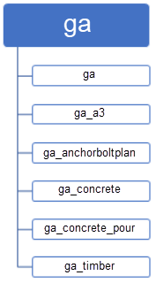

In Tekla Structures 2020, the drawing sizes are defined in the table layouts with the new layout editor:


Example
The following example explains the points of interest when copying layout files (* .lay file) from an earlier Tekla Structures version to Tekla Structures 2020.
Suppose you have created your own layout in Tekla Structures 2019i, in the example below the layout customer:

In here, the following table layouts are defined:

The following template layouts are linked to the Fixed sizes:

As you can see in the images above, the template layout customer_dummy is not linked to any Fixed sizes.
We copy the layout file (*.lay file) customer to Tekla Structures 2020 and open the layout file in the new Layout editor:
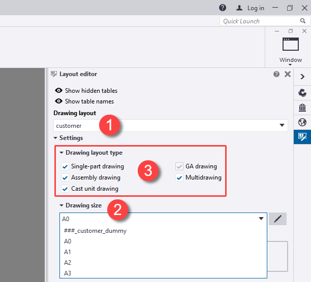
Drawing layout customer is selected (1) and you see in the list Drawing size (2) that the table layout customer_dummy which is unassociated, automatically names the size ###_customer_dummy.
(You can now also select to which drawing types (3) you want to apply drawing layouts).
General: In case you open a layout file (.lay) with unassociated table sets created in previous versions of Tekla Structures, Tekla Structures generates a drawing size to every table set automatically, and names the size ###_[TABLE LAYOUT NAME]. The position of the templates in the layout is unchanged. The name and the size need to be checked and, if necessary, you need to modify these.
You must select the unassociated table layout and click the button
 , the following dialog box appears:

Change the name and the size (column Width and Height) and click OK to save the changes:

... to be able to use the customized drawing size in drawings:

Click here and here for more detailed information about the improved Layout editor.
Image

1 = Drawing frame
2 = Drawing views
3 = Templates
4 = Table layout
To define the drawing layout and customize the layout in earlier Tekla Structures versions, you could use:
- the command Drawings & Reports > Drawing properties > Drawing layout in the Model Editor:
Image

This command is no longer available in Tekla Structures 2020.
- the Layout Editor. You use the Layout Editor for creating and editing drawing layouts and define the positions for templates.
Image

You can use the Layout Editor for customizing layouts directly, quickly and easily. Because of that, Tekla Structures 2020 provides a new and improved Layout Editor (via File > Editor> Drawing layout editor) where you can customize layouts and define new layouts . All changes you make are shown in real time in the Layout Editor:
Image

NOTE: New drawing layouts in Tekla Structures 2020 are also saved as *.lay files, just like in previous Tekla Structures versions. However, these new * .lay files are not compatible with * .lay files you created using the command Drawings & Reports > Drawing properties > Drawing layout or the Layout editor in earlier Tekla Structures versions. This means that you cannot use the new layout in earlier Tekla Structures versions.
General
In earlier Tekla Structures versions, the layout was divided as follows, for example the layout ga including corresponding table layouts:
Image

Image

In Tekla Structures 2020, the drawing sizes are defined in the table layouts with the new layout editor:
Image

Image

Example
The following example explains the points of interest when copying layout files (* .lay file) from an earlier Tekla Structures version to Tekla Structures 2020.
Suppose you have created your own layout in Tekla Structures 2019i, in the example below the layout customer:
Image

In here, the following table layouts are defined:
Image

The following template layouts are linked to the Fixed sizes:
Image

As you can see in the images above, the template layout customer_dummy is not linked to any Fixed sizes.
We copy the layout file (*.lay file) customer to Tekla Structures 2020 and open the layout file in the new Layout editor:
Image

Drawing layout customer is selected (1) and you see in the list Drawing size (2) that the table layout customer_dummy which is unassociated, automatically names the size ###_customer_dummy.
(You can now also select to which drawing types (3) you want to apply drawing layouts).
General: In case you open a layout file (.lay) with unassociated table sets created in previous versions of Tekla Structures, Tekla Structures generates a drawing size to every table set automatically, and names the size ###_[TABLE LAYOUT NAME]. The position of the templates in the layout is unchanged. The name and the size need to be checked and, if necessary, you need to modify these.
You must select the unassociated table layout and click the button
Image
Image

Change the name and the size (column Width and Height) and click OK to save the changes:
Image

... to be able to use the customized drawing size in drawings:
Image

Click here and here for more detailed information about the improved Layout editor.
Single command for creating various types of rebar dimension marks
Previously there were three separate commands for creating rebar dimension marks:

The workflow for creating rebar dimensions marks has been simplified in Tekla Structures 2020 so that there is only one command available now in the ribbon in the tab Dimensioning:

... as a command in the context menu:

... and via the function Quick launch:

In addition, Tekla Structures 2020 includes a few new settings for dimensioning:

reinforcement_dim_ctc_tag:

reinforcement_dim_label:

reinforcement_dim_range:

The style of the rebar dimension mark is controlled by the properties on the new Rebar tab in the Dimension Properties dialog box:
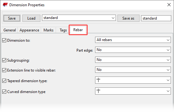
- Dimension to specifies whether dimensions are created between All rebars or between the Start and end rebars only. Part edge adds closing dimensions to the edge of the part in reinforcing bar group dimensions. This setting is only available if Dimension to is set to All rebars.
- Subgrouping specifies whether subgroups are created for different rebar spacings within a rebar object so that dimension marks can display the subgroup properties.
- Extension line to visible rebar controls the display of extension lines to the visible rebars.
- Tapered dimension type specifies whether skewed dimensions have skewed or horizontal representation.
- Curved dimension type specifies whether curved dimensions have curved or horizontal representation.
For more detailed information about rebar dimension marks, click here.
Image

The workflow for creating rebar dimensions marks has been simplified in Tekla Structures 2020 so that there is only one command available now in the ribbon in the tab Dimensioning:
Image

... as a command in the context menu:
Image

... and via the function Quick launch:
Image

In addition, Tekla Structures 2020 includes a few new settings for dimensioning:
Image

reinforcement_dim_ctc_tag:
Image

reinforcement_dim_label:
Image

reinforcement_dim_range:
Image

The style of the rebar dimension mark is controlled by the properties on the new Rebar tab in the Dimension Properties dialog box:
Image

- Dimension to specifies whether dimensions are created between All rebars or between the Start and end rebars only. Part edge adds closing dimensions to the edge of the part in reinforcing bar group dimensions. This setting is only available if Dimension to is set to All rebars.
- Subgrouping specifies whether subgroups are created for different rebar spacings within a rebar object so that dimension marks can display the subgroup properties.
- Extension line to visible rebar controls the display of extension lines to the visible rebars.
- Tapered dimension type specifies whether skewed dimensions have skewed or horizontal representation.
- Curved dimension type specifies whether curved dimensions have curved or horizontal representation.
For more detailed information about rebar dimension marks, click here.
Display frames of drawing view permanently
In Tekla Structures 2020 (and also from Tekla Structures 2019i SP3 on), you can permanently display the frames of drawing views (and not only when you move the mouse cursor over the frame of a view):

You can add the line
The view frames are not displayed by default in drawings:

Image

You can add the line
XS_VIEW_FRAME_HIDING_DISABLE=TRUE to any *.ini file.The view frames are not displayed by default in drawings:
Image

Tools/plugins
BTL Export (ML019) - BVX Export (ML027) - Randek Export (ML077) - BVN Export (ML081)
Tekla Warehouse includes several export tools for generating production data for wood framing machines such as BTL Export (ML019), BVX Export (ML027), Randek Export (ML077) and BVN Export (ML081). These tools are updates frequently because of new functionalities or improvements or fixes:

Set an alert
You can set an alert in Tekla Warehouse for the tools to get informed automatically in case the content changes or if a new version is available:

Image

Set an alert
You can set an alert in Tekla Warehouse for the tools to get informed automatically in case the content changes or if a new version is available:
Image

Spiral Concrete Stair (m006)
Plugin Spiral Concrete Stair (m006) now includes a new tab Casting plates for modeling casting plates:


You can use the plugin for modeling spiral concrete stairs. For detailed information, click the Help button in the plugin.
Image

Image

You can use the plugin for modeling spiral concrete stairs. For detailed information, click the Help button in the plugin.
Floor Opening Mark (m007)
Tekla Structures 2020 includes the plugin Floor Opening Mark (m007) in the Drawing Editor:

You use the plugin to create and use your own symbols for openings and recesses in parts in drawings. The big advantage of the new plugin is that you can create a symbol per opening/recess with a desired setting:

You can use this plugin if you want a symbol for a stairwell opening and not for a grommet, for example.
You can of course still use the default symbols for openings and recesses of parts in drawings. However, you always create default symbols per view. In this way, all openings/recesses will have or will not have a symbol.
Image

You use the plugin to create and use your own symbols for openings and recesses in parts in drawings. The big advantage of the new plugin is that you can create a symbol per opening/recess with a desired setting:
Image

You can use this plugin if you want a symbol for a stairwell opening and not for a grommet, for example.
You can of course still use the default symbols for openings and recesses of parts in drawings. However, you always create default symbols per view. In this way, all openings/recesses will have or will not have a symbol.
Floor Panel Marking (m011)
Tekla Structures 2020 now includes the new plugin Floor Panel Marking (m011) in the Drawing Editor:

You can use the plugin for creating one label for several parts:

You can set the content of the label to your needs.
Image

You can use the plugin for creating one label for several parts:
Image

You can set the content of the label to your needs.
Sequence Tool (ML013)
Tekla Structures includes macro Sequence Tool (ML013) by default. You can use this macro to assign user defined attributes (UDA's) to parts, for example unique control numbers for (foundation)piles, assembly sequences or to sort truck loads by assigning group numbers:

The macro has been improved and now supports items.
For more detailed information about the macro, click the Help button in the macro's dialog box.
Image

The macro has been improved and now supports items.
For more detailed information about the macro, click the Help button in the macro's dialog box.
Trimming steel (m036)
Tekla Structures includes the plugin Trimming steel (m036) for several versions.

... to position trimmer profiles in hollow core slabs:

The plugin fits the hollow core slab and positions a trimming profile including support hands. All profile properties and offsets can be defined in the plugin. There is also one option available to define the load at the support location.
The plugin is improved in Tekla Structures 2020 and you only have to pick two points for positioning the trimming profile.
In addition, the tab Support hands in now included where you can define multiple types of hands:

and on the Advanced tab you can define an offset to the picked points:

Image

... to position trimmer profiles in hollow core slabs:
Image

The plugin fits the hollow core slab and positions a trimming profile including support hands. All profile properties and offsets can be defined in the plugin. There is also one option available to define the load at the support location.
The plugin is improved in Tekla Structures 2020 and you only have to pick two points for positioning the trimming profile.
In addition, the tab Support hands in now included where you can define multiple types of hands:
Image

and on the Advanced tab you can define an offset to the picked points:
Image

Slab dimensioning (DR060)
The tool Slab dimensioning (DR060) was included in earlier Tekla Structures versions by default:

... to dimension cladding profiles in a certain way in drawings:

This tool is moved to Tekla Warehouse and therefore no longer available in Tekla Structures by default. In addition, the tool has been renamed to Object dimensioning tool.
The tool can also be used for cladding in a sloped plane, for example a roof plane.
Image

... to dimension cladding profiles in a certain way in drawings:
Image

This tool is moved to Tekla Warehouse and therefore no longer available in Tekla Structures by default. In addition, the tool has been renamed to Object dimensioning tool.
The tool can also be used for cladding in a sloped plane, for example a roof plane.
Opening Dimensioning (m061)
The tool Opening Dimensioning (m061) was included in earlier Tekla Structures versions by default:

This tool is moved to Tekla Warehouse and therefore no longer available in Tekla Structures by default. In addition, the tool has been renamed to Opening and edge dimensioning.
Image

This tool is moved to Tekla Warehouse and therefore no longer available in Tekla Structures by default. In addition, the tool has been renamed to Opening and edge dimensioning.
Electra sockets (m083)
You can use the tool Electra sockets (m083) in Tekla Structures for modeling electra sockets including openings for boxes and tubes in timber wall panels. The tool is improved to dimension and show all zones correctly.

The tool is available in Tekla Warehouse.
Image

The tool is available in Tekla Warehouse.
CS Rotate Coordinates Of Cross Section (ML087)
Tekla Structures 2020 includes the new plugin Rotate Coordinates Of Cross Section (ML087):


General
You can add fixed profiles to the profile catalog in Tekla Structures by defining the cross section via File > Catalogs > Define profiles > Define cross section using polygon:

Click here for detailed information about adding profiles by defining the cross section via picking corner points of the cross section.
You pick the points of the cross-section in a specific order (1-2-3-etc.) to determine the orientation of the profile.
To change the orientation after defining the profile, so that the profiles are correct regarding to the orientation in the output, such as drawings and export files, you can use the new plugin CS Rotate Coordinates Of Cross Section (ML087).
Image

Image

General
You can add fixed profiles to the profile catalog in Tekla Structures by defining the cross section via File > Catalogs > Define profiles > Define cross section using polygon:
Image

Click here for detailed information about adding profiles by defining the cross section via picking corner points of the cross section.
You pick the points of the cross-section in a specific order (1-2-3-etc.) to determine the orientation of the profile.
To change the orientation after defining the profile, so that the profiles are correct regarding to the orientation in the output, such as drawings and export files, you can use the new plugin CS Rotate Coordinates Of Cross Section (ML087).
Steel Frame components
In previous Tekla Structures versions, there were several tools available for steel framing. These tools have been moved to Tekla Warehouse and are therefore no longer available in Tekla Structures by default. Several new tools have also been added and are available:

TIP: Don't forget to set an alert in Tekla Warehouse for the tool to get informed automatically in case the content changes or if a new version is available.
Image

TIP: Don't forget to set an alert in Tekla Warehouse for the tool to get informed automatically in case the content changes or if a new version is available.
Bolts between points (m093)
The tool Bolts between points (m093) is included in Tekla Structures since several versions to quick and easily model bolt groups:

It is preferred to switch snap option Snap to lines and edges on so that you can snap to the edges of parts. The yellow arrowhead indicates the direction of the bolt group. If you want to change the direction, move the cursor closer to the opposite end of the line.
The tool is improved and includes new options:
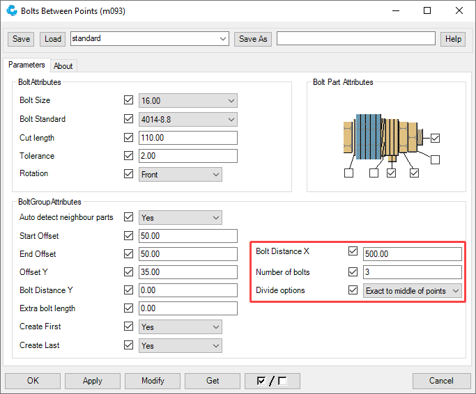
Here you can define the bolt spacing, the number of bolts and the options to divide the bolts in X direction.
For more detailed information about this tool, click the Help button in the tool's dialog box.
Image

It is preferred to switch snap option Snap to lines and edges on so that you can snap to the edges of parts. The yellow arrowhead indicates the direction of the bolt group. If you want to change the direction, move the cursor closer to the opposite end of the line.
The tool is improved and includes new options:
Image

Here you can define the bolt spacing, the number of bolts and the options to divide the bolts in X direction.
For more detailed information about this tool, click the Help button in the tool's dialog box.
CS_Plaster_board_from_UDA (ML074) and Plasterboard pre estimation (m098)
In previous Tekla Structures versions, the tools CS_Plaster_board_from_UDA (ML074) and Plasterboard pre estimation (m098) were available by default. The tools are not included in Tekla Structures 2020 anymore, but the tools are available in Tekla Warehouse now.

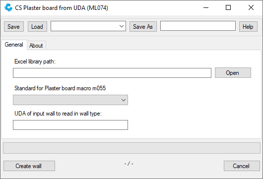

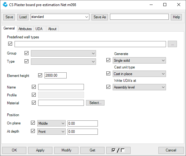
Image

Image

Image

Image

Create line rectangle (m111)
Tekla Structures 2020 now includes the new plugin Create line rectangle (m111) in the Drawing Editor:


You can use the plugin in drawings for creating lines and rectangles.
Image

Image

You can use the plugin in drawings for creating lines and rectangles.
Lifting clamps (m118)
Tekla Structures 2020 now includes the new plugin Lifting clamps (m118):


You can use the plugin to define the position of lifting clamps on hollow core slabs.
By using the plugin, a surface is added to the hollow core slabs, which is also shown in drawings. You can dimension the surface in the drawing in relation to the hollow core slabs to show the location:

Image

Image

You can use the plugin to define the position of lifting clamps on hollow core slabs.
By using the plugin, a surface is added to the hollow core slabs, which is also shown in drawings. You can dimension the surface in the drawing in relation to the hollow core slabs to show the location:
Image

Create curve (m119)
Tekla Structures 2020 now includes the new plugin Create curve (m119):

to model complex curves:

You can use this plugin to model a Bézier curve (parametric curve type) but also a cubic curve. You can model them as a construction line or as a poly profile and you can also create points on the line.
Image

to model complex curves:
Image

You can use this plugin to model a Bézier curve (parametric curve type) but also a cubic curve. You can model them as a construction line or as a poly profile and you can also create points on the line.
Multi Report Generator (m122)
Tekla Structures 2020 includes the improved tool Multi Report Generator (m122) which allows you to generate multiple reports at once:

Besides you can generate reports by phase or by assembly cast unit.
Image

Besides you can generate reports by phase or by assembly cast unit.